
Warped quads, also known as bow-tie quads, are sometimes formed when accidentally mixing up the vertex order during face creation. In a less extreme case they might be formed when moving a single vertex of a planar quad. This small illustration shows how these may look in the 3D-view:

In the 3D view, the warped face on the right didn't seem out of the ordinary but when rendered it does not show uniform shading:

Both objects are planes and consist of a single face with four vertices. The one on the left is a bow-tie quad. Its right edge is rotated a full 180 degrees resulting in an ugly, black triangle where we see the back of the warped face. The plane on the right shows no noticeable distortion in the 3D view even though its upper-right vertex is moved a considerable distance along the z-axis (our line of sight). When rendered however, the distortion of the right plane is clearly visible. The visible distortion of slightly warped quads may be overcome by setting the smooth attribute of a face that will interpolate the vertex normals along the face resulting in a smooth appearance. Slightly warped quads are almost inevitable when modeling or deforming a mesh by an armature and whether they result in visible problems depends on the situation. Often it is helpful if you can identify and select them to make your own judgment.
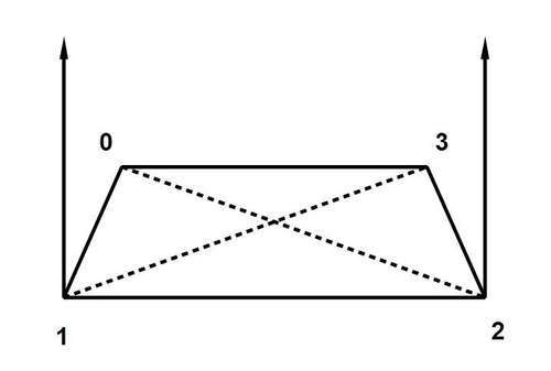
Warped quads can be identified by checking whether the normals of the triangles that form the quad are pointing in the same direction. A flat quad will have its triangle normals pointing in the same direction as shown in the following figure:
Whereas in a warped quad these normals are not parallel:
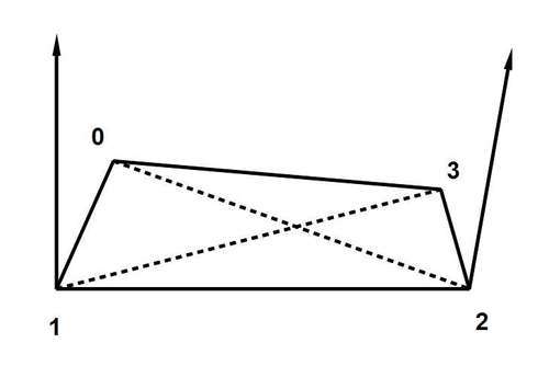
These triangle normals are not the same as vertex normals: those are defined as the average of all face normals of the faces sharing a vertex so we will have to calculate these triangle normals ourselves. This can be done by taking the cross product of the edge vectors, that is, the vectors defined by the two vertices at the end of each edge. In the examples shown we have the left triangle normal formed by taking the cross product of the edge vectors 1 → 0 and 1 → 2 and the right triangle by taking the cross product of the edge vectors 2 → 1 and 2 → 3.
It does not matter whether we traverse our edges clockwise or counterclockwise but we have to be careful to be consistent in ordering edges when calculating the cross products because the sign will be reversed. Once we have our triangle normals we can check whether they point in exactly the same direction by verifying that all components (x, y, and z) of one vector are scaled by the same factor when compared to the corresponding components of the second vector. To give us somewhat more flexibility however, we would like to calculate the angle between the triangle normals and select a face only if that angle exceeds some minimum. We do not have to devise such a function ourselves because the Blender.Mathutils module provides the AngleBetweenVecs() function.
It is possible to construct four different triangles within a quad but is not necessary to compare all triangle normals—any two normals will suffice because moving a single vertex of a quad will alter three of the possible four triangle normals.
Armed with all this information, the outline for our tool will look like this:
- Show pop up for minimum angle.
- Verify that the active object is a mesh and in edit mode.
- Enable face select mode.
- For all faces, check if the face is a quad and if so:
- Calculate the triangle normal defined by vertex 0, 1, and 2
- Calculate the triangle normal defined by vertex 1, 2, and 3
- Calculate the angle between normals
- If angle > minimum angle, select the face
This translates in the following code for the actual detection and selection (the full script is provided as warpselect.py):
def warpselect(me,maxangle=5.0):
for face in me.faces:
if len(face.verts) == 4:
n1 = ( face.verts[0].co - face.verts[1].co ).cross( face.verts[2].co - face.verts[1].co )
n2 = ( face.verts[1].co - face.verts[2].co ).cross( face.verts[3].co - face.verts[2].co )
a = AngleBetweenVecs(n1,n2)
if a > maxangle :
face.sel = 1
As you can see, our outline corresponds almost one-to-one to the code. Note that AngleBetweenVecs() returns the angle in degrees so we can directly compare it to maxangle which is also in degrees. Also, there is no need to implement the cross product of two vectors ourselves as Blender's Vector class is well stocked with all sorts of operators. Before we can call this function we have to take care of an important detail: in order to select faces, face selection mode should be enabled. This can be done as follows:
selectmode = Blender.Mesh.Mode()
Blender.Mesh.Mode(selectmode | Blender.Mesh.SelectModes.FACE)
To illustrate the less well-known fact that select modes are not mutually exclusive we set the face select mode in addition to any mode already selected by combining values with a binary or operator (|). At the end of the script we restore the mode that was active.