
Where pydrivers enable us to drive the change of one IPOCurve by the change in another, PyConstraints provide us with ways to let object properties change only in a limited way.
Of course, Blender has many simple constraints predefined as we saw in previous sections and often a combination of simple constraints may be exactly what you want. But say you want your objects to move about freely within a non-rectangular area, for example to simplify the allowed placement of traffic lights and phone booths on a street grid. How would we achieve that? Enter pyconstraints.
PyConstraints are Python scripts that should be present as a text block in Blender's text editor and start with a comment line identifying it as a constraint:
#BPYCONSTRAINT
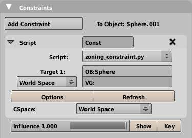
A Python constraint should contain three functions called doConstraint(), doTarget(), and getSettings(). The first two are invoked anytime we move either the target or the constrained object and the last one is called when the user clicks the Options button that is present once the user has selected a pyconstraint. The following screenshot shows the Constraints tab once a pyconstraint is selected.
The easiest way to understand what these functions do is by looking at the built-in constraint template that we can use as a basis to write our own constraints. It is accessible in the text editor from the menu Text | Script Templates | Script Constraint. If clicked, it will create a new text block that can be selected from the dropdown at the bottom of the text editor.
The Blender constraint template contains a lot of helpful comments as well, but here we list mostly the bare functions. Also, the template creates a dummy properties window. We will encounter properties in the next section so our example of getSettings() here will be almost empty. As shown the functions will implement a functional constraint, however, nothing is actually constrained. Location, rotation, and scale of the constrained object are all kept the same.
def doConstraint(obmatrix, targetmatrices, idprop):
# Separate out the transformation components for easy access.
obloc = obmatrix.translationPart() # Translation
obrot = obmatrix.toEuler() # Rotation
obsca = obmatrix.scalePart() # Scale
# code to actually change location, rotation or scale goes here
# Convert back into a matrix for loc, scale, rotation,
mtxloc = Mathutils.TranslationMatrix(obloc)
mtxrot = obrot.toMatrix().resize4x4()
mtxsca = Mathutils.Matrix([obsca[0],0,0,0], [0,obsca[1],0,0], [0,0,obsca[2],0], [0,0,0,1])
# Recombine the separate elements into a transform matrix.
outputmatrix = mtxsca * mtxrot * mtxloc
# Return the new matrix.
return outputmatrix
The doConstraint() function will be passed the transformation matrix of the constrained object and a list of transformation matrices for every target object. It will also receive a dictionary of properties of the constraint that may be accessed by name.
The first thing we do is to separate out the translation, rotation, and scale components of the constrained objects' transformation matrix. The translation part will be a vector with the x, y, z position and the scale part will be a vector with scaling factors along the x, y, and z-axis. The rotation part will be represented by a Euler vector with the rotation about the three principal axes. (Eulers greatly simplify working with rotations in 3D but are rather difficult to grasp at first. Wikipedia has a great page on Euler angles http://en.wikipedia.org/wiki/Euler_angle but for now, it is easiest to think of Eulers as a rotation separated out as rotations around the local x, y, and z axes.) We could separate any of the target object's transformation matrices as well, if we wanted, and then modify the transformation components of the transformation matrix of the constrained object in any way we wish.
The function as shown here does nothing but converts the different transformation components back to matrices by using API methods (where available) and then recombines them by using matrix multiplication to a single matrix that is subsequently returned.
The doTarget() function is called prior to calling doConstraint() and gives us the opportunity to manipulate the target matrix before it is passed to doConstraint(). Its arguments are the target object, the subtarget (either a Bone or a vertex group for a target armature or mesh respectively), the target matrix, and the properties of the constraint. In a later section, we exploit this opportunity to store a reference to the target object in the properties so that doConstraint() may access that information that it otherwise could not access. If we do not wish to alter anything then returning the target matrix as is will suffice, as shown in the following code:
def doTarget(target_object, subtarget_bone, target_matrix, id_properties_of_constraint):
return target_matrix
Likewise, if there is no need to offer the user the possibility to specify additional properties, getSettings() may simply return. If we do want to show a pop up, getSettings() is the place where it should happen. We see an example of that in a later section as well. The following code is a valid "do nothing" implementation:
def getSettings(idprop):
return
As the moon and earth revolve around each other they feel each other's gravitational attraction. On earth this will result in tides, but the solid body of the earth and moon will be distorted as well, although this effect is small. Now there is a lot more to tides than attraction alone (http://en.wikipedia.org/wiki/Tides), but we can show the gravitational distortion in an exaggerated way by applying constraints.
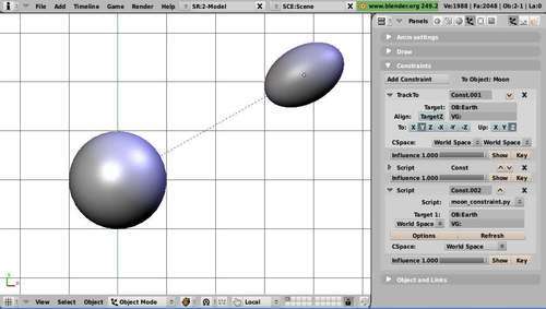
One way of doing this is to use a TrackTo constraint to orient an axis of our constrained object towards the attracting object and add a second constraint that scales the constrained object along the same axis. The size of the scale will depend on the inverse distance between the constrained object and the target object. The effect is illustrated in the next screenshot where the effect of a TrackTo constraint is combined with the script constraint moon_constraint.py.
We will have to write this distance-dependent scaling ourselves. If we take the constraint template provided by Blender we can leave the doTarget() and getSettings() functions as is, but we do have to write a suitable doConstraint() function (full code available as moon_constraint.py):
def doConstraint(obmatrix, targetmatrices, idprop):
obloc = obmatrix.translationPart() # Translation
obrot = obmatrix.toEuler() # Rotation
obsca = obmatrix.scalePart() # Scale

tloc = targetmatrices[0].translationPart()
d = abs((obloc-tloc).length)
d = max(0.01,d)
f = 1.0+1.0/d
obsca[1]*=f

mtxloc = Mathutils.TranslationMatrix(obloc)
mtxrot = obrot.toMatrix().resize4x4()
mtxsca = Mathutils.Matrix([obsca[0],0,0,0], [0,obsca[1],0,0], [0,0,obsca[2],0], [0,0,0,1])
outputmatrix = mtxsca * mtxrot * mtxloc
return outputmatrix
We left out any lines related to properties as we do not implement any user-configurable properties for this constraint. The highlighted lines show what we have to do to calculate the distance-dependent scaling.
The first line gets the location of our target. Next, we calculate the distance between the constrained object and the target and limit this to a minimum (slightly larger than zero) to prevent a division by zero in the next highlighted line. The formula used here is nowhere near an approximation of any gravitational influence but behaves nicely enough for our purpose; the scale factor will be 1.0 if d is very large and will smoothly increase as the distance d becomes smaller. The final highlighted line shows that we alter the scale only of the y-axis, that is, the axis we orient towards the target object with the TrackTo constraint.
Note
Cyclic dependencies:
If both objects have a comparable mass, the gravitational distortion would be of comparable size on both objects. We might be tempted to add the TrackTo and moon_constraint.py constraints to both objects to see the effect they assert on each other, but unfortunately that will not work because it will create a cyclic dependency and Blender will protest.
This is like the "snap to vertex" mode that is available in Blender from the menu Object | Transform | Snap (see http://wiki.blender.org/index.php/Doc:Manual/Modelling/Meshes/Snap_to_Mesh for more about snapping) except that the effect is not permanent (the object reverts to its unconstrained position once the constraint is removed) and the strength of the constraint can be modulated (animated even) by changing the Influence slider.
In the constraints that we designed so far, only the position of the target object was needed to calculate the effects on the constrained object. This position was readily available to the doConstraint() function as the matrices of the targets were passed as arguments. Now we are facing a different challenge though: if we want to snap to a vertex we must have access to the mesh data of the target object, but the target object is not passed to the doConstraint() function.
The way around this obstacle is the idprop argument that is passed to doConstraint(). Before doConstraint() is called, Blender first calls doTarget() for each target object. This function is passed as a reference to the target object and to the properties of the constraint. This allows us to insert a reference to the target object in these properties and because these properties are passed to doConstraint(), this provides us with a means to pass the necessary information to doConstraint() to get at the Mesh data. There is a minor point to consider here though: Blender properties can only be numbers or strings so we cannot actually store a reference to an object but have to settle for its name. Because a name is unique and Blender's Object.Get() provides a way to retrieve an object by name, this is not a problem.
The code for doConstraint() and doTarget() will look like this (the full code is provided as zoning_constraint.py):
def doConstraint(obmatrix, targetmatrices, idprop):
obloc = obmatrix.translationPart().resize3D()
obrot = obmatrix.toEuler()
obsca = obmatrix.scalePart()
# get the target mesh
to = Blender.Object.Get(idprop['target_object'])
me = to.getData(mesh=1)
# get the location of the target object
tloc = targetmatrices[0].translationPart().resize3D()
# find the nearest vertex in the target object
smallest = 1000000.0
delta_ob=tloc-obloc
for v in me.verts:
d = (v.co+delta_ob).length
if d < smallest:
smallest=d
sv=v
obloc = sv.co + tloc
# reconstruct the object matrix
mtxrot = obrot.toMatrix().resize4x4()
mtxloc = Mathutils.TranslationMatrix(obloc)
mtxsca = Mathutils.Matrix([obsca[0],0,0,0], [0,obsca[1],0,0], [0,0,obsca[2],0], [0,0,0,1])
outputmatrix = mtxsca * mtxrot * mtxloc
return outputmatrix
def doTarget(target_object, subtarget_bone, target_matrix, id_properties_of_constraint):
id_properties_of_constraint['target_object']=target_object.name
return target_matrix
The highlighted lines show how we pass the name of the target object to doConstraint(). In doConstraint() we first retrieve the target mesh. This may throw an exception, for example, if the target object is not a mesh, but this will be caught by Blender itself. The constraint will not be affected then and an error is shown on the console, but Blender will proceed happily.
Once we have the mesh data of the target object we retrieve the object location of the target object. We need this because all vertex coordinates are relative to this. Next we compare the location of the constrained object to all the vertex locations of the target mesh and remember the closest one to calculate the object location of the constrained object. Finally, we reconstruct the transformation matrix of the constrained object by combining various transformation components as before.
Now that we can constrain an object to the closest vertex on a target mesh we can see that something is missing: the object is not oriented in a meaningful way. This might not always be a problem, for example, trees will normally point upward, but in many situations it would be nice if we could orient the constrained object perpendicular to the surface. This is the same for all practical purposes, as orienting the constrained object along the vertex normal of the vertex it has been snapped to.
Therefore, after finding the closest vertex we determine the angle between the vertex normal and the z-axis (that is, we arbitrarily define the z direction as 'up') and then rotate the constrained object by the same amount around the axis perpendicular to both the vertex normal and the z-axis. This will orient the constrained object along that vertex normal. If the constrained object was rotated manually before adding the constraint these previous rotations would be lost. If that is not what we want, we can apply any rotations permanently before adding the constraint.
To implement this alignment feature, our code will change (zoning_constraint.py contains these changes already): doConstraint() will have to calculate the rotation part of the transformation matrix. We have to calculate the rotation angle, the rotation axis, and then the new rotation matrix. The highlighted part of the following code shows that the essential tools for these calculations are already provided by the Mathutils module:
vnormal = sv.no
if idprop['NormalAlign'] :
zunit=Mathutils.Vector(0,0,1)
a=Mathutils.AngleBetweenVecs(vnormal,zunit)
rotaxis=zunit.cross(vnormal)
rotmatrix=Mathutils.RotationMatrix(a,4,"r",rotaxis)
mtxrot = rotmatrix
else:
mtxrot = obrot.toMatrix().resize4x4()
In the preceding code we can see that we have made an alignment dependent on the NormalAlign property. Only if it is set do we calculate the necessary transformation. Therefore, we need to adapt getSettings() as well because the user needs a way to select whether he wants alignment or not:
def getSettings(idprop):
if not idprop.has_key('NormalAlign'): idprop['NormalAlign'] = True
align = Draw.Create(idprop['NormalAlign'])
block = []
block.append("Additional restrictions: ")
block.append(("Alignment: ",align,"Align along vertex normal"))
retval = Draw.PupBlock("Zoning Constraint", block)
if (retval):
idprop['NormalAlign']= align.val
As shown, the NormalAlign property will be set to True by default. The option is then presented as a simple pop up with a toggle button. If the user clicks outside the pop up or presses the Esc key, the return value from PupBlock() will be None and we won't change the NormalAlign property. Otherwise, it will be set to the value of the toggle button.
The effects are shown in the illustrations. The first one shows a small pine tree constrained to a vertex of a simple subdivided ground plane. It is snapped to the exact vertex location but its z-axis points straight up along the global z-axis. The following screenshot shows a fir tree constrained to a vertex in a craggy landscape.

If we turn on the NormalAlign property we see that the tree model is no longer pointing straight up, but that its z-axis is aligned along the direction of the vertex normal of the vertex it is snapped to. The following screenshot shows a fir tree constrained to a vertex and aligned along the vertex normal.

It is possible to restrict the vertices the model can snap to even further, for example, to just the vertices belonging to a vertex group. In the following illustration, our model cannot move beyond the extent of the vertex group that is shown in white. How this might be accomplished is shown in the next section.

What if we want to restrict the vertices we can snap an object to? This can be achieved by defining a vertex group and then consider only vertices from this vertex group as candidates to snap to. The code needed for this would take just a couple of lines and the relevant part of doConstraint() would look like this (the highlighted code shows the additional lines dealing with the matching against a vertex group):
# get the target mesh
to = Blender.Object.Get(idprop['target_object'])
me = to.getData(mesh=1)
# get the location of the target object
tloc = targetmatrices[0].translationPart().resize3D()
# find the nearest vertex in the target object
smallest = 1000000.0
delta_ob=tloc-obloc

try:
verts = me.getVertsFromGroup(idprop['VertexGroup'])
for vi in verts:
d = (me.verts[vi].co+delta_ob).length
if d < smallest :
smallest = d
si = vi
obloc = me.verts[si].co+tloc
vnormal = me.verts[si].no
except AttributeError:

for v in me.verts:
d = (v.co+delta_ob).length
if d < smallest:
smallest=d
sv=v
obloc = sv.co + tloc
vnormal = sv.no
The try/except construction ensures that if the VertexGroup property refers to a nonexistent vertex group, we will get the chance to check all vertices. Of course, we now need a way for the user to select the vertex group, so getSettings() will have to be adapted too. We settle for a simple string input field where the name of a vertex group can be typed. There is no checking if the vertex group exists and if we do not want to restrict the snapping to a vertex group, then we can either leave this input field blank or type in the name of a nonexistent group. Not very elegant but it works (added lines highlighted):
def getSettings(idprop):

if not idprop.has_key('VertexGroup'): idprop['VertexGroup'] = 'Zone'

if not idprop.has_key('NormalAlign'): idprop['NormalAlign'] = True

vgroup = Draw.Create(idprop['VertexGroup'])

align = Draw.Create(idprop['NormalAlign'])
block = []
block.append("Additional restrictions: ")

block.append(("Vertex Group: ",vgroup,0,30,"Vertex Group to restrict location to"))

block.append(("Alignment: ",align,"Align along vertex normal"))
retval = Draw.PupBlock("Zoning Constraint", block)
if (retval):

idprop['VertexGroup']= vgroup.val

idprop['NormalAlign']= align.val
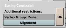
The next screenshot shows how the input box for the vertex group may look:
Note
Note that the script constraint also presents the user with a VG string input field that may refer to a vertex group, but this is different from the vertex group input field that we show the user in the Options pop up. This VG field will alter the way the constraint looks at a target. If a valid vertex group is set here, the target matrix passed to doConstraint() will be that of the median position of the vertices in the vertex group.