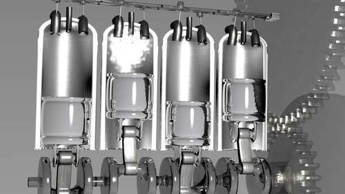
Imagine that we want to demonstrate how a four-stroke internal combustion engine works. Such an engine has a lot of moving parts and many of them are related in complex ways.
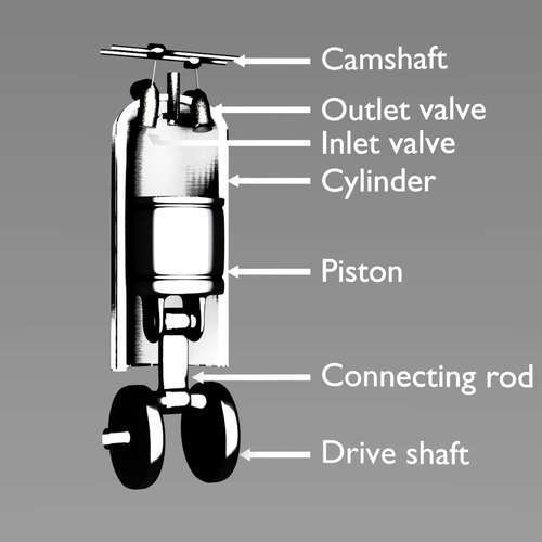
To see what these exact relations are, it might be useful to have a look at the following illustration. It lists the names that we will use when we refer to the various parts. (I am neither an automotive engineer nor a mechanic so these part names may not be accurate but at least we will be talking about the same things. For more information you may want to read http://en.wikipedia.org/wiki/Four-stroke_cycle.)
Before we start to configure the parts to have their rotation and position driven by another part, it is a good thing to think ahead: in real life, the pistons inside the cylinders are propelled by the expansion of the ignited fuel and the pistons drive the drive shaft (or crank-shaft) with the attached flywheel and a distribution belt (or in our case some gears, that are not shown here) transfers that motion back to the camshafts that drive the motion of the inlet and outlet valves. Obviously, we cannot follow this concept directly as there is no fuel object of some sort to drive other objects so it makes more sense to reverse the chain of relations. In our setup the flywheel will drive the drive shaft and the different gears and the drive shaft will drive most other objects, including the piston and its connecting rod. We will also drive the energy of the lamp positioned at the tip of the spark plug by the rotation of the drive shaft.
The drive shaft will simply follow the rotation of the flywheel as will the lower gear (this could be implemented with a copy rotation constraint just as well but here we choose to implement everything by pydrivers). The corresponding pydrivers for the RotX channel will look like this:
ob('Flywheel').RotX/(2*m.pi)*36
This may look awkward for something just copying a rotation but remember that rotations are stored as radians while pydriver expressions should return rotations as degrees divided by 10.
The top gear and both the camshafts will also follow the rotation of the flywheel but with the speed reduced to half and with the direction of the rotation reversed:
m.degrees(ob('Flywheel').RotX*-0.5)/10.0
To illustrate how to access functions in Python's math module we did not do the conversion to degrees ourselves but used the degrees() function supplied by the math module.
We modeled the camshafts with the cam pointing exactly downward. If we want to drive the x-axis rotation of the inlet camshaft by the rotation of the drive shaft we have to take into account that it moves at half the speed. Also, its rotation lags behind a bit to match the ignition cycle of the cylinder as it opens the inlet valve on the first downstroke and closes the valve just before the ignition spark:
ob('DriveShaftPart').RotX/(2*m.pi)*18+9
The expression for the outlet camshaft is almost identical except for the amount it lags behind (here 24, but tuning this engine is left to real mechanics):
ob('DriveShaftPart').RotX/(2*m.pi)*18+24
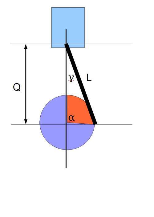
The movement of the piston is limited to just the vertical, but the exact motion is somewhat more involved to calculate. We are interested in the position of the quantity Q—see the preceding figure—and the distance between the center of the drive shaft and point where the connecting rod (L in the diagram) connects to the piston. Because the length of the connecting rod is fixed, Q will vary as a function of the rotation angle α of the drive shaft. The distance from the center of the drive shaft to point where the connecting rod is connected to the drive shaft is also fixed. We call this distance R. Now we have a triangle with sides Q, L, and R and a known angle α. As three of these quantities (L, R, and α) are known, we can calculate the fourth, Q, by using the cosine rule (http://en.wikipedia.org/wiki/Law_of_cosines). Therefore, we define a function q() in pydrivers.py that will return the length Q when L,R, and α are given:
def q(l,r,a): return r*cos(a)+sqrt(l**2-(r*sin(a))**2)
The expression for the LocZ channel of the piston will then simply call this function with the appropriate values for the arguments:
p.q(1.542,0.655,ob('DriveShaftPart').RotX)
The precise values for L and R were taken from the mesh by noting the position of appropriate vertices of the connecting rod and the drive shaft in the Transform Properties window. (N key in the 3D View)
The connecting rod itself may use the same expression for its LocZ channel as we carefully made the mesh origins of the piston and the connecting rod to coincide.
However, the motion of the connecting rod is not limited to the z-location as it will rotate around the x-axis centered on the point connecting it to the piston. The angle of this rotation (γ in the diagram) can be derived from the quantities L, R, and α:
def topa(l,r,a):
Q=q(l,r,a)
ac=acos((Q**2+l**2-r**2)/(2*Q*l))
if a%(2*pi)>pi : ac = -ac
return -ac
The pydriver expression for RotX will then look like this:
m.degrees(p.topa(1.542,0.655,ob('DriveShaftPart').RotX))/10.0
The inlet and outlet valves are driven by the rotation of their respective camshafts. The outline of the actual cam is quite complex so here, we use not the actual form of that outline but approximate it by something that looks good enough (that is, open the valve in a fluent yet brisk motion at the correct moment). The following graph shows the valve travel as a function of rotation angle:
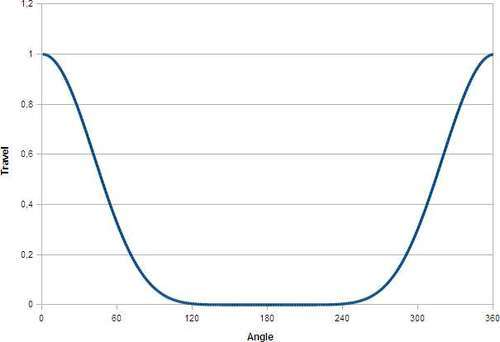
To this end, in pydrivers.py we define a function spike() that will take the rotation of the camshaft as its argument and returns a value between 0.0 and 1.0 that rises steeply around the zero angle:
def spike(angle):
t = (cos(angle)+1.0)/2.0
return t**4
Now the motion of the valve is linear but the line it follows is tilted by 10 degrees (forward for the inlet valve, backward for the outlet valve) so we have to drive two channels, LocZ and LocY, each multiplied by the correct amount to effect the slanted motion. We therefore define two functions in pydrivers.py:
def valveZ(angle,tilt,travel,offset):
return cos(radians(tilt))*spike(angle)*travel+offset
def valveY(angle,tilt,travel,offset):
return sin(radians(tilt))*spike(angle)*travel+offset
Both functions will return a distance given the rotation angle of the object driving it. The tilt is the amount that the valve is tilted (in degrees), travel is the maximum distance the valve will travel along the tilted line, and offset is a value that allows us to tweak the position of the valve. The corresponding pydriver expressions for the LocZ and LocY channels of the inlet valve will then become:
p.valveZ(ob('CamInlet').RotX+m.pi,-10.0,-0.1,6.55)
and
p.valveY(ob('CamInlet').RotX+m.pi,-10.0,-0.1,-0.03)
(The expressions for the outlet valve look the same but with a positive tilt angle.)
Until now, all channels have been object channels, that is, locations and rotations. But it is also possible to drive other channels, and that is precisely what we need to drive the energy of the lamp positioned at the tip of our spark plug. In pydrivers.py we first define a helper function topi() that, besides the rotation angle of the driving object, will take an angle h (in radians) and an intensity i as arguments. It will return that intensity if the angle of the driving object is between 0 and h and will return zero outside this range. Because the input angle may be larger than two times pi (when the driving object is rotated more than full circle), we correct this by the highlighted modulo operation:
def topi(a,h,i):
m = a%(2*pi)
r=0.0
if m<h: r=i
return r
The pydriver expression for the energy channel (called "Energ" in the IPO editor window) can then be expressed as follows:
p.topi(ob('DriveShaftPart').RotX/2+m.pi,0.3,0.5)
As shown, this expression will 'fire' the spark plug for the first 17 degrees or so (0.3 radians) of its cycle by setting the energy to 0.5.
Once we have modeled a single cylinder and taken care of driving the motions of the individual parts, our next step is to duplicate the cylinders to create a set like the opening illustration of this chapter. In principle we can select all parts, duplicate them by pressing Shift + D, and adjust the timing of the individual driven channels.
There is a snag, however. When using Shift + D rather than Alt + D we make actual copies of the object meshes instead of merely referring to the same. We would expect the same for other items associated with an object, such as materials, textures, and IPOs. This is not the case however as Blender, by default, does not duplicate those last three categories when duplicating an object. This would be awkward, as a change in the IPO of the first piston for example would affect all duplicated pistons as well.
We could make those copies unique afterward (by clicking on the user count field of those IPOs for instance and confirm the make single user? popup) but this is tedious as it would have to be repeated for each copy.
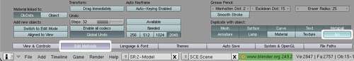
A better way is to alter the Duplicate with object settings in the Edit Methods screen of the User Preferences window as shown in the preceding screenshot. In this way, IPOs associated with an object will be made into unique copies when duplicating an object. A screenshot of the User Preferences window with buttons to duplicate IPOs (highlighted) is shown above.
The result of our labors, a four cylinder engine with gears to transfer the motion of the drive shaft to the camshafts is available as engine001.blend. A still image from the animation available at http://vimeo.com/7170769 is shown in the next screenshot: