
Your drawing is not a world unto itself. Many times, you need to work with files or data from other applications. Here are some possibilities:
Working for a client who uses another CAD program
Placing an image of a logo into your titleblock
Inserting a drawing into a report
Inserting a spreadsheet into your drawing
Using a satellite photo as a basis to create a map
You have several ways of working with other applications:
You can import another file format so that the entire file is brought into your drawing.
You can export to another file format so that the entire drawing can be imported into another application.
You can export to an image format that others can view.
You can import a raster image (bitmap) without changing any file format. A raster image is made up of dots, called pixels, as opposed to vectors. AutoCAD and AutoCAD LT are vector programs.
You can import, or export to, a DXF file, which is a way of interchanging drawings between AutoCAD or AutoCAD LT and other CAD programs.
As you can imagine, the possibilities are endless. This chapter explains how to work with other applications.
You can export to several other file formats, thereby enabling you to save the file in another format. You can also import several formats. This section explains how to do both.
You usually export objects to an image format and then use that format in another application. You may also export a drawing to import it into another CAD program. The method you use depends on the type of format that you want. Table 27.1 shows the file formats that AutoCAD and AutoCAD LT can create. Except as noted, you are prompted to select objects to export.
Table 27.1. Export File Formats
Format | Description |
|---|---|
WMF | Windows Metafile Format — a Windows vector format. |
ACIS | A solid modeling file format stored as |
STL | Exports a single solid in a format usable with stereolithography (AutoCAD only). |
BMP | Windows bitmap — a raster format. |
EPS | Encapsulated PostScript — a format used by certain printers to create high-quality text and images. Exports all objects (AutoCAD only). |
DXF | Drawing Interchange Format is a text format for CAD drawings that most CAD programs accept. You can choose from Releases 2007, 2004, 2000, and 12 DXF file formats. Exports the entire drawing. |
DXB | Another format for transferring CAD drawings, but in binary format (not text). Used less often than the DXF format. |
DWF | Design Web Format — a format for placing a drawing on a Web site. |
DGN | Format of Bentley Microstation drawings. You can export the entire drawing as a Version 7 or 8 DGN file. |
JPG | Joint Photographic Expert Group — a raster (bitmap) format commonly used on the Web. It can be compressed, but will lose some detail. Often used for photographs because it supports many colors. |
TIF | Tagged Image File Format — a raster (bitmap) format often used for scanned images. Provides good quality. |
PNG | Portable Network Graphics — a raster (bitmap) format that supports many colors and also compresses well without losing detail. It also supports transparency. |
Adobe Acrobat Portable Document Format. |
Note
For more information on the DWF file format, see the next chapter. The DWF format is a way to share your drawings with others either directly or on the Internet.
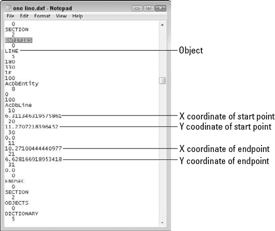
The DXF (drawing interchange file) format is a text file that contains all the information in a 2D drawing. Because most CAD programs accept this format, you can export to DXF and send the file to someone else who can then import it into another CAD program. Figure 27.1 shows the part of a DXF file that defines a line. Not only are objects defined, but all layers, linetypes, and other settings are defined as well. The file lists codes that specify a certain type of data (for example, the X coordinate of a line's endpoint), followed by the values for the codes (for example, 7.55).
To create a DXF file, choose Application Button
Some users work with companies that use Bentley Microstation, another CAD product. It creates DGN files. The DGNEXPORT command allows you to translate your drawing file (and any xrefs) according to your preferences. (I cover xrefs in Chapter 19.) To export a drawing to DGN format, choose Application Button
Choose the version you want from the Files of Type drop-down list, choose a location and filename, and click Save. The Export DGN Settings dialog box opens, as shown in Figure 27.2.
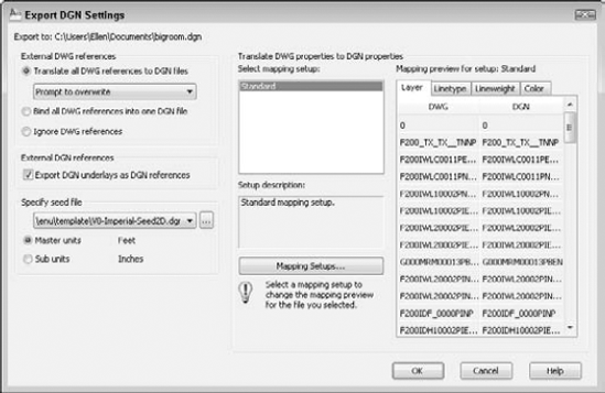
In the Export DGN Settings dialog box, you can specify the following settings:
External DWG References. You specify whether you want to translate external references in AutoCAD DWG format into DGN references. You can keep them as external references, combine them into one drawing, or ignore them.
External DGN References. You may have DGN drawings in your AutoCAD drawing as underlays. You can choose whether or not to include DGN underlays.
Specify Seed File. You can choose a seed file from available samples in the Template folder or from another location. You can also choose master or subunits. A DGN file can have two sets of measurement units — master and sub. Choose which units you want to use.
Note
A seed file for a DGN file is similar to a drawing template file. It contains settings such as the measurement units (imperial or metric), the Origin, and whether the file is 2D or 3D.
Translate DWG Properties to DGN Properties. You can specify mapping setups to define how layers, linetypes, lineweights, and colors are translated during the export. The default setup is called Standard. To create a new mapping setup, click the Mapping Setups button to open the DGN Mapping Setups dialog box. Click New to create a new mapping setup. Name the setup and click Continue to complete the process.
You can check the results of a setup by clicking the four tabs in the Export DGN Settings dialog box.
Keep in mind that some objects and properties are not translated properly. Examples are:
Many AutoCAD and AutoCAD LT users like to use the DWF format to share drawings when they don't want to send the drawing itself — whether for security reasons or because a colleague doesn't have the program. DWF files display the drawing in a free viewer or on the Web, and they support zooming, panning, layers, named views, and so on. I cover the DWF format in Chapter 28.
However, non-CAD users, such as clients, may not want to install software to view DWF files, or they may simply feel more comfortable with an Adobe Acrobat PDF (Portable Document Format) file. The Adobe Acrobat Reader, which is the viewer for PDF files, is widely available and free.
Note
The DWFx format creates files whose 2D data conform to Microsoft's XPS format. This format is an image format similar to PDF. Windows Vista comes with an XPS reader, so people with Windows Vista will be able to view the new DWF files without a separate reader. People with Windows XP and Microsoft .NET Framework 3.0 will also be able to view DWFx files.
To export to the PDF format, you can use the PLOT command and plot to a file by using a plotter configuration (PC3) file. (See Chapter 17 and Appendix A for more information.) Follow these steps:
Display the drawing that you want to export.
Start the PLOT command.
In the Printer/Plotter section of the Plot dialog box, click the Name drop-down list and choose DWG To PDF.pc3.
To adjust PDF settings, click Properties and make changes in the Plotter Configuration Editor. For example, you can merge overlapping lines. Click OK, and then choose whether you want the changes to apply to the current plot or to all plots using that configuration file.
Make any other adjustments that you want to make in the Plot dialog box and click OK.
In the Browse for Plot File dialog box, name the PDF file (or accept the default) and choose a location.
Click Save.
Note
Another option is to choose Output tab
When you're done, you can view your drawing in the Adobe Acrobat Reader.
Note
The PUBLISH command, covered in Chapter 28, can also create single-sheet or multi-sheet PDF files. You can publish from a sheet set, as I explain in Chapter 26, and create a multi-sheet PDF file of the sheets. Finally, you can insert a PDF as an underlay; for more information, see Chapter 19.
To export to JPG, PNG, or TIF format, use the JPGOUT, PNGOUT, or TIFOUT command, respectively, on the command line. Then choose a folder, click Save, and select objects at the prompt.
When you want to export a drawing to another file format, whether to create an image file or import that file into another application, you export the drawing. WMF, which is a vector image file, is probably the most commonly used format. You can also export to a BMP file. To export a drawing to another format (except for JPG, PNG, and TIF), follow these steps:
Choose Application Button

Choose the file format that you want in the Files of Type drop-down list.
Find the desired folder by using the Save In drop-down list and the Folder box, and change the filename in the File Name text box if desired.
Click Save.
Note
You can also export to 3D DWF format (AutoCAD only). See Chapter 28 for more information on DWF files.
The WMFBKGND system variable controls the background of WMF files that you export, whether using the Export Data dialog box, copying and pasting, or dragging and dropping. When the value of this system variable is Off (the default), the background color of the file is transparent, so that it doesn't interfere with the background on which it is pasted. You can set it to On so that the background is the same as that of the drawing background.
The WMFFOREGND system variable works in tandem with the WMFBKGND system variable. It controls the foreground (line) color of objects when you export WMF files. WMFFOREGND takes effect only when you set WMFBKGND to 0, which makes the background color transparent. A value of 0, the default, swaps foreground and background colors, if necessary, to make the foreground color (the objects) darker than the background color. A value of 1 does the opposite — the foreground color is lighter than the background color.
Note
The drawing used in the following exercise on exporting a WMF file, ab27-a.dwg, is in the Drawings folder on the DVD.
STEPS: Exporting a WMF File
Open
ab27-a.dwgfrom the DVD.Save the file as
ab27-01.dwgin yourAutoCAD Biblefolder. You can see it in Figure 27.3.Choose Application Button
If necessary, locate your
AutoCAD Biblefolder. Click Save.At the
Select objects:prompt, make a window around the red rectangle to include all three objects. End object selection to end the command and create the WMF file.

To import WMF, SAT, or DGN files, choose Insert tab
In the following exercise, you practice importing a WMF file.
Note
The file used in the following exercise on importing a WMF file, ab27-01.wmf, is in the Results folder on the DVD. If you did the previous exercise, you can also find the file in your AutoCAD Bible folder.
STEPS: Importing a WMF File
Open a new drawing by using the
acad.dwtoracadlt.dwttemplate.Save the file as
ab27-02.dwgin yourAutoCAD Biblefolder.Enter wmfin

If you did the previous exercise, locate your
AutoCAD Biblefolder in the Import WMF dialog box. Chooseab27-01.wmf. If you didn't do the previous exercise, findab27-01.wmfin theResultsfolder of the DVD. In the Import WMF dialog box, choose ToolsAt the
Specify insertion point or [Basepoint/Scale/X/Y/Z /Protate]:prompt, pick any point near the top of your screen. Notice that the insertion point is at the top-left corner of the image.Press Enter to accept the defaults for X and Y scales and rotation angle. Notice that you've lost the solid fill in the logo. The red rectangle came in fine. Also, you may see an added rectangle around the extents of the image where the extents of the screen were when the WMF file was created.
Pick the image. Notice that everything is selected with one grip at the insertion point. Choose Home tab
Choose Home tab
Start the WMFIN command, and select Metafile (*wmf) from the Files of Type drop-down list. Choose
ab27-01.wmf. Click Options to open the Import Options (WMF In) dialog box. This time, check Wide Lines, uncheck Wire Frame (No Fills), and click OK. In the Import WMF dialog box, click Open to import the file. Pick in a different location in your drawing, and accept the defaults.Explode the inserted image. (You may have to pick it at its edge.) Erase the rectangle and the remaining line at the right. Now you have an image that is very close to the original. The text comes in with the Bookman Old Style font (or the font that you used — the same font as the original), although the spacing is not exact. Also, the logo now has its solid fill. It should look like Figure 27.4.
Save your drawing.

If someone sends you a file in DGN (Bentley Microstation) format, you can import this file by choosing Application Button
Select a design model from the DGN file. A design model is like AutoCAD's model space. A DGN drawing may have multiple model spaces. You can only import one at a time; if you need more than one, you need to import them separately.
External DGN References. You can choose to ignore any xrefs, translate all xrefs into individual files, or keep the references as DGNs and use them as underlays. (See Chapter 19 for more information about DGN underlays.)
Conversion units. The DGN has a master unit and a subunit (such as feet and inches or meters and millimeters). The dialog box displays the units, and you choose which one to import as one unit. For example, if you choose to import the file using master units of feet, it will appear 1½ the size of the same drawing using subunits (inches). Be sure to measure and make sure that you choose the right units.
Explode text nodes to text elements. Text nodes are multiple lines of text in one object, such as AutoCAD's Mtext. Text elements would be single lines of text, such as Dtext. If you want to keep the file looking the same as the original, especially around curves and arcs, then you should check this option.
Translate DGN properties to DWG properties. You specify how layers, linetypes, lineweights, and colors will appear after import. You can save these property settings for use during both import and export of DGN files.
Click OK when you're done, to import the drawing.
Note
You can attach PDF, DWF, and DGN files (Microstation drawings) to your drawing. When you attach a file, you are not importing it; rather, you are just displaying it along with your drawing. These files are similar to xrefs, so I discuss them in Chapter 19, where I cover xrefs.
If someone sends you a file in DXF format, it probably contains a drawing that was created in another CAD program. You can open that drawing in AutoCAD or AutoCAD LT. You can import a DXF file in two ways:
To import a DXF file into a new drawing, choose Application Button
To insert a DXF file into an existing drawing, choose Insert tab
You can easily attach scanned images, digital photographs, and other image files into your drawings. You can use these images to insert a logo, show a photo or artist's rendering of your model, and for many other uses. Although raster (bitmap) images are generally much larger files than vector drawings, you can easily zoom and pan throughout your drawing. You can usually plot these raster images, as well. Table 27.2 shows the raster formats that AutoCAD 2010 supports.
Table 27.2. Raster Formats Supported by AutoCAD 2010
File Type | File Extension | Comments |
|---|---|---|
BMP |
| Windows and OS/2 bitmap |
CALS1 |
| Mil-R-Raster 1 |
GIF |
| CompuServe Graphics Exchange Format |
GeoSPOT |
| GeoSPOT (used in GIS applications); HDR and PAL files with correlation data must be in the same folder |
JFIF or JPEG |
| Joint Photographic Experts Group |
FLIC |
| Autodesk Animator FLIC |
IG4 |
| Image Systems Group 4 |
PCX |
| Paintbrush |
PICT |
| Macintosh picture |
PNG |
| Portable Network Graphic |
RLC |
| Run-Length Compressed |
TARGA |
| True Vision Raster-Based Data Format |
TIF |
| Tagged Image File Format |
You can easily attach an image into your drawing and manipulate it in a number of ways. To attach an image, choose Insert tab
Locate the image that you want to attach and click Open. The Attach Image dialog box opens, as shown in Figure 27.5; this dialog box lets you specify how to attach the image. You can specify the insertion point, scale, and rotation in the dialog box or on-screen. This dialog box is very similar to the Insert dialog box that you use when inserting drawings and blocks. (See Chapter 18.)
Tip
You can specify a relative path (rather than the full path) for an image. A relative path stores only the relationship between the drawing and the image. Choose Relative Path from the Path Type drop-down list. If you put the image in the same folder as the drawing, only the drawing name is stored. Using a relative path and placing the image in the same folder as the drawing is ideal when you need to share drawings with people who don't have the same folder structure as you.
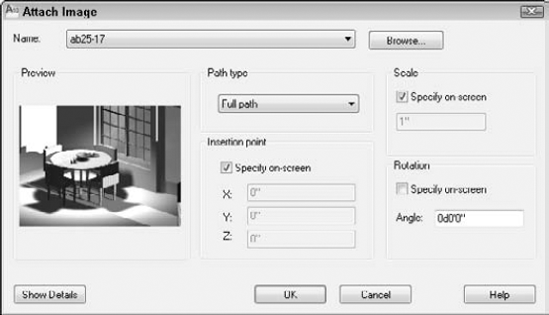
Click Show Details to open the bottom of the dialog box. Here the dialog box lists the resolution (number of pixels) per drawing unit and the size in pixels, as well as the size in drawing units. The Current AutoCAD Unit is based on the specification in the Units dialog box. (See Chapter 5 for more information.) This information is helpful in deciding how to scale an image. Click OK to insert the image.
Note
Raster images usually don't scale up very well. If you enlarge them too much, the image looks grainy. However, the higher the resolution, the better the image will look when enlarged. You can also use the DesignCenter to insert raster images, as described in Chapter 26.
Note
The Express Tools contain a command, IMAGEEDIT (enter imageedit
As with xrefs, you may need a way to keep track of your images, especially if you attach many of them. Choose Insert tab
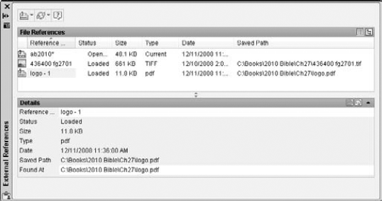
You can use the List View and Tree View buttons at the top-right corner of the File References pane to view your images as a flat list or a hierarchical (tree) format. Use the Details and Preview buttons at the top-right corner of the bottom pane to view either file details or a preview. Here are the other options:

Right-click any item and choose Detach to delete it from your drawing and all references to it in the drawing database.
Right-click any item and choose Unload to remove the display of the item but retain the reference to it. Later, you can reload the image to redisplay it.
Right-click any item and choose Reload to redisplay an item after you've unloaded it or made changes to it.
Tip
You can attach rendered images that you've saved as PCX, JPG, JPEG, PNG, TIF, TGA, or BMP files. A great way to do this is to create a floating viewport in paper space for the rendered image, letting your clients see not only the regular drawing, but also the rendered result on one sheet of paper. (Figure 25.17 in Chapter 25 was created this way.) Remember that you can plot shaded and rendered images. See Chapter 17 for details.
A powerful feature of AutoCAD lets you clip images just as you clip external references. Large images can slow down your drawing display. You may also simply find it distracting to see parts of an image that you don't need for your work. For example, if you attach an aerial photograph of a city block but want only one house, being able to clip around the house and not display the rest of the image is a great advantage.
Note
You can use the same procedure described here to clip an xref (see Chapter 19), a PDF, a DWF (see Chapter 28), or a DGN file.
To clip an image, follow these steps:
Attach an image.
Choose Insert tab
At the
Select Object to clip:prompt, select the image. Pick the image at its border.At the prompt, press Enter to accept the default of creating a new clipping boundary.
Tip
An alternative is to select the image first. The Image tab appears, where you can click the Create Clipping Boundary button.
At the
Specify clipping boundary or select invert option [Select polyline/Polygonal/Rectangular/Invert clip] <Rectangular>:prompt, press Enter to create a rectangular clip, choose Polygonal to create a multisided boundary, or Select Polyline to convert a closed polyline to a clipping boundary. You can also choose Invert Clip to invert the clipping of the image, show the image that is on the outside on the boundary rather than on the inside.To use a closed polyline as a polygonal boundary, select the closed polyline that you want to use as the clipping boundary.
For a rectangular boundary, pick a first point and the opposite corner to create the boundary.
For a polygonal boundary, specify the first point and then use the
Specify next point or [Undo]:prompt to pick points until you've completed the boundary. You can use the Undo option to undo the last pick, or the Close option (which appears after you pick three points) to close the final boundary. AutoCAD creates a rubber-band boundary as you pick points so that you can see the result. Press Enter when you're done.
Tip
You can modify a clipped image's boundary by using its grips. Select the clipped image to displays its grips. Use the square grips to resize the clipping boundary and click the arrow grip to invert the clipping boundary.
At the Enter image clipping option [ON/OFF/Delete/New boundary] <New>: prompt, you can also use the following options:
Choose ON to turn on a boundary that you previously turned off.
Choose OFF to turn off a boundary and redisplay the entire image.
Choose Delete to delete the clipping boundary.
Note
Images are 2D objects. The clipping boundary must be parallel to the plane of the image.
You can control several aspects of image display, using the commands detailed in this section. Control the image display to adjust the properties that control how the image looks.
The ADJUST command lets you change the brightness, contrast, and fade of an image. Select the image by picking its border. The Image tab appears. In the Adjust panel, use the Contrast, Fade, and Brightness sliders to adjust the image.
You can also adjust an image's display by selecting an image, right-clicking, and choosing Image
To adjust image quality, use the IMAGEQUALITY command on the command line. AutoCAD displays the Enter image quality setting [High/Draft] <High>: prompt. Choose either High or Draft. This command affects the display of all the images in a drawing. Plotting is always at high quality. Use this command when a high-quality image slows down performance. A regen is not necessary after you change this setting.
If the image format that you're using supports transparent pixels, you can use the TRANSPARENCY command to create a transparent background for your image. This works for bi-tonal or grayscale images. (Bi-tonal images have only a foreground color and a background color.) By default, transparency is turned off.
To turn transparency on, select the image. The Image tab appears, where you can click the Transparency button. Click it again to turn transparency off. You may need to do a regen. Other objects in your drawing will now be visible through the background of your image.
The FRAME system variable controls the frame that surrounds all images in a drawing. (It also works for DWFs, PDFs, DGNs, and xrefs.) Choose Insert tab
Hide Frames. Turns off the frame, both in the drawing display and when plotting.
Display and Plot Frames. Turns on the frame, both in the drawing display and when plotting.
Display but Don't Plot Frames. Displays the frame in the drawing, but doesn't plot it. This is the default value.
FRAME can have a fourth value, *Frames Vary*, which denotes that one of the individual frame settings is different from the FRAME system variable. You can override the frame settings used for images by changing the value of the IMAGEFRAME system variable to 0 (not visible or plotted), 1 (displayed and plotted), or 2 (displayed but not plotted).
Turning off the frame often improves the way the image looks. However, you select an image by clicking its frame. Therefore, using the Hide Frames value means that you cannot select the image, except when using commands specific to images, such as TRANSPARENCY, ADJUST, and CLIP.
When an image has a border, the border displays the properties of the layer that was current when you attached the image.
The DRAWORDER command changes the display order of objects, including raster and OLE objects. (OLE is discussed later in this chapter.) This command is very helpful when working with raster and OLE objects, where you may or may not want to hide the other objects in your drawing. You can move an object to the top or bottom or change its order in relation to another object — above or below it. To change an object's display order, choose Home tab
Tip
The TEXTTOFRONT command controls the order of both text and dimensions. Use this command to ensure that text is always on top and never obscured by other objects. In Chapter 13, I explain how to use a background mask to make text more legible.
Note
The drawing used in the following exercise on working with raster images, ab27-b.dwg, and the images ab27-b.tif and ab27-b1.bmp, are in the Drawings folder on the DVD. This exercise works with AutoCAD only.
STEPS: Working with Raster Images
Open
ab27-b.dwgfrom the DVD.Save the file as
ab27-03.dwgin yourAutoCAD Biblefolder.Enter plan on the command line and press Enter twice to view the model from the top (plan view).
Choose Insert tab
In the Select Reference File dialog box, choose
ab27-b.tiffrom the DVD. Click Open. In the Attach Image dialog box, click Show Details. Notice that the image is 1 × 0.61 units. Compared to the house, it is tiny.In the Attach Image dialog box, uncheck Specify On-Screen for the Scale factor (if it's checked), and change the scale factor to 5. Click OK.
At the
Specify insertion point <0,0>:prompt, pick any point on the left side of the screen. The image is still tiny, but that's okay. Choose Zoom on the status bar and define a window to zoom closely into the image, as shown in Figure 27.7.Click the border of the image; the Image tab appears. In the Adjust panel, change the Contrast to 60 and the Brightness to 40.
With the image still selected, choose Create Clipping Boundary in the Clipping panel of the Image tab. Follow the prompts:
Specify clipping boundary or select invert option [Select polyline/Polygonal/Rectangular/Invert clip] <Rectangular>:
Specify first corner point:If Object Snap is on, turn it off. Pick
in Figure 27.7. Specify opposite corner point:Pick.If necessary, zoom out so that you have room to insert another image. Choose Insert tab
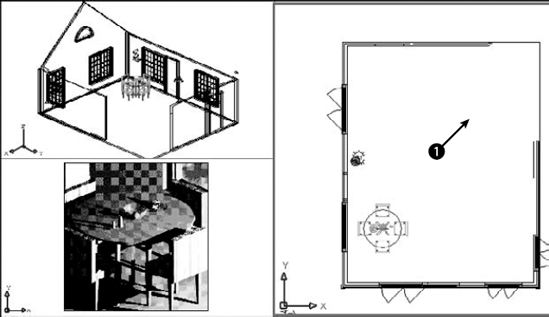
Click the Layout1 button on the status bar (or the Layout1 tab) to enter paper space, which has three floating viewports. Double-click the bottom-left viewport. Enter plan on the command line and press Enter twice. You should now see the images as a small dot to the left of the house. Use Zoom Window to zoom into the rendered table. Your drawing should now look like Figure 27.8.
Click the right viewport. If necessary, pan the house to the right until you can see the two images that you attached. Move the Cottonmill Houses image to

Click the Insert tab. In the Insert panel, click the Frames drop-down list and choose Hide Frames. AutoCAD removes the frames from the two images.
Save your drawing.
To maximize the data that you have in other documents, you can insert objects from other applications into your drawing. For example, you may have a description of your drawing in a word-processing application or in a table in a spreadsheet. You can use the Windows Clipboard to share data between applications.
Note
In Chapter 18, I explain how to use the Windows Clipboard to copy and move material from one drawing to another. Chapter 13 includes a discussion of several techniques for importing text into your drawing.
You can insert data (text or images) created with other applications into a drawing in three ways:
Embed the object if you want to be able to return to the source application to edit the object. When you double-click the object, the source application opens so that you can edit the object.
Paste the object when you don't need any connection with the source application.
Link the object when you want to retain a permanent link to the source file so that when the source file is changed, the drawing data changes accordingly.
You can use the Clipboard to move material from one application to another and take advantage of the special options for pasting, linking, and embedding data. Linking and embedding are often referred to as Object Linking and Embedding, or OLE. You can also use drag-and-drop between applications.
You have three ways to embed data from other applications. Each method has its advantages and disadvantages.
Here's the first way:

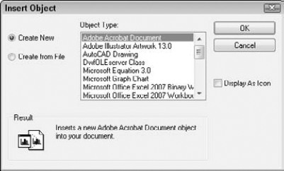
Do one of the following:
If you want to create a new file in the other application, choose Create New, choose the application that you want to use from the Object Type list, and click OK. The other application opens so that you can create the new data. When you're done, choose File
If you want to choose an existing file, choose Create from File. Click Browse to find the file. Click Open. You return to the Insert Object dialog box, where you can choose Link to link the data (described in the next section of this chapter). Choose OK. The file appears at the top-left corner of your screen with handles that you can use to move and/or resize the object.
Here's the second way:
Open the source application, select the data, and copy it to the Clipboard. Leave the source application open.
If your drawing is open, switch to it by choosing its button on the task bar. Otherwise, open it.
In your drawing, choose Home tab
In the Paste Special dialog box, choose the first option, which lets you embed the object as an object of the source application. Click OK.
You can now close the other application.
The third way to insert data is to use drag-and-drop:
Open the drawing where you want to embed the data.
Open the source application and select the data.
Press Ctrl and click the selected data again, holding down the mouse button.
Drag the data to the AutoCAD or AutoCAD LT button on the Windows task bar and continue to hold down the mouse button until your drawing displays.
Drag the data to the desired location in your drawing.
Using INSERTOBJ gives you the option of creating a new file on the spot in the other application. You don't have to keep the other application open when you return to your drawing. Note that you cannot create a link if you're creating a new file.
Using the Clipboard enables you to insert part of a file — for example, part of a spreadsheet — which can be a great advantage. You need to keep the other application open until you paste the object into your drawing.
You can control the size of text and the plot quality of OLE objects. Choose Application Button
OLE objects have a few limitations:
If they're contained in a block or an external reference, they may not be displayed or plotted.
In certain cases, OLE objects can be printed out only on Windows system printers. You can usually configure your plotter to be the system printer.
OLE objects don't rotate with your drawing when you use a PLOT rotation. To work around this, you can use the system printer's Landscape setting.
OLE objects don't display or plot if displayed in a rotated viewport. If you need an OLE object to be displayed in a viewport, you should not rotate the viewport.
Tip
If you don't mind a few steps, you can sometimes get good results importing large Excel spreadsheets by way of Microsoft Word, as follows: In Excel, use Save As to save the spreadsheet in Text (Tab delimited) format. Insert the file into Word (choose Text Files from the Open dialog box's Files of Type drop-down list). Select the entire file and choose Table
Tip
If you try to use HIDE on a 3D model that contains OLE objects, the OLE objects disappear! The solution is to insert them in paper space. You can then hide the 3D model in one floating viewport and display the OLE object in another.
When you copy data to the Clipboard, it's stored in several formats, depending on the type of data. You can then choose which format you want to use when you paste it into your drawing, using the PASTESPEC (Paste Special) command. Choosing the right format can make a big difference, by enabling you to edit the data in your drawing as you wish.
To paste data by using PASTESPEC, open the source application, select the data, and copy it to the Clipboard. Leave the source application open.
If your drawing is open, choose its button on the task bar. If not, open it. In your drawing, choose Home tab
Table 27.3. Paste Special Data Types
Characteristics | |
|---|---|
Object of Source Application | The object is inserted at the top-left corner of your drawing. You cannot explode the object, but you can select it and then resize it or move it by using its handles. This is an embedded object — if you double-click it, the source application opens, letting you edit the object by using the source application's tools. |
Picture (Metafile or Enhanced Metafile) | The object is inserted at the top-left corner of your drawing. You cannot explode the object, but you can select it and then resize it or move it by using its handles. You cannot edit the object. It maintains good quality when scaled up. |
Bitmap | The object is inserted at the top-left corner of your drawing. You cannot explode the object, but you can select it and then resize it or move it by using its handles. You cannot edit the object. |
AutoCAD Entities | You see prompts for an insertion point, scale factor, and rotation angle. You can explode the object into drawing objects. (Objects were once called entities in AutoCAD and AutoCAD LT.) Text objects maintain their original font and formatting. |
Image Entity | You see prompts for an insertion point, scale factor, and rotation angle. The object is inserted as approximately a 1 × 1-unit square. It is a kind of bitmap. You can explode it, but then you lose the image! |
(Unicode) Text | The object is inserted at the top-left corner of your drawing. You can explode it, but the text then loses the original formatting and font. |
The best choice depends on the type of data that you're pasting. For a spreadsheet, the Picture, Bitmap, and Image Entity choices aren't useful, but they would be quite appropriate if you were pasting in an image.
You can also copy drawing objects to the Clipboard and paste them into another application, such as a word-processing document, a spreadsheet, or a presentation program. Figure 27.10 shows a PowerPoint slide that includes a model from an AutoCAD drawing. To paste drawing objects into another application, select the objects that you want to copy. Choose Home tab
Tip
You can hide a 3D view and copy and paste the view into another application. However, you cannot copy and paste a rendered view. To bring a rendered view into another application, save it as an image and import it. Chapter 25 covers saving rendered images. You can freeze any layers that you don't want to include, such as dimension and text layers.

Inserting AutoCAD as an ActiveX Component into PowerPoint
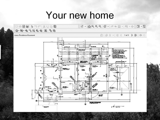
When you insert or paste AutoCAD objects into another document, such as a Word document or PowerPoint presentation, the objects are static images. What if you could display your AutoCAD drawing dynamically, with zooming and panning? You could then show your intended audience all the detail you want.
It turns out that you can. You can use the DWF format (covered in more detail in Chapter 28) and insert it into any version of Word, Excel, or PowerPoint that supports ActiveX components. Viewers need the free Autodesk Design Review, which they can download at www.autodesk.com/designreview. Here are instructions for PowerPoint:
Create the DWF file. (See Chapter 28 for instructions.)
In PowerPoint, choose a slide layout that gives you room for the DWF file.
Choose Insert
Click Create New and then choose Autodesk DWF Viewer Control. Click OK. On your slide, you see a box with handles.
If you want, resize or move the box. (If you deselect the box, it may disappear. Click inside the box to select it again.)
Right-click the box and choose Autodesk DWF Viewer Control Object
In the Autodesk DWF Viewer Control Properties dialog box, on the SourcePath tab, type the path to the DWF file or click browse to browse to the file. Click OK.
In your PowerPoint presentation, enter Slide Show view. You can now pan, zoom, turn layers on and off, print, and so on from within your presentation.
In PowerPoint 2007, you need to make sure that ActiveX settings in the Trust Center are not disabled. Then you need to display the Developer tab. (Choose Office button
You can insert data from a spreadsheet or text document and maintain a link to the original file, so that if the original file changes, the inserted data is updated as well, very similar to xrefs. For example, you could use this feature to place a schedule of doors and windows in an architectural drawing or a bill of materials in a mechanical drawing. You have two ways to link data.
Note
You can also create a link to an Excel spreadsheet. You can even change the Excel spreadsheet from within AutoCAD. In other words, you have a link in both directions. For more information, see Chapter 13.
First, you can link data by using INSERTOBJ, as described earlier in this chapter. Second, you can use the Clipboard by following these steps:
Open the source application, select the data, and copy it to the Clipboard.
If your drawing is open, display it. If not, open it.
In your drawing, choose Home tab
In the Paste Special dialog box, choose Paste Link. Click OK.
When you create a link, you don't have all the format options that you do when you simply paste. You can create a link in the source application's format only.
When you open a drawing containing a link, a message appears, asking whether you want to update the links. In this way, you can update the links whenever you open the drawing. You can manage links by typing olelinks on the command line, which opens the Links dialog box, as shown in Figure 27.11.
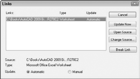
The Links dialog box enables you to manually update the links at any time by choosing Update Now. You may want to do this if you know that someone has changed the source of the link during your drawing session. You can also break the link, open the source, or change the source in this dialog box.
Remember that if you give a drawing to someone else, you also need to include any attached images or embedded objects. If the person does not have the source application for an embedded object, you can paste it in as an image.
Note
The drawing, ab27-c.dwg, and the file, ab27-c.xls, used in the following exercise on pasting, linking, and embedding objects are in the Drawings folder on the DVD.
To do the following exercise, you need a spreadsheet application. I use Microsoft Excel in this exercise.
STEPS: Pasting, Linking, and Embedding Objects
Open
ab27-c.dwgfrom the DVD.Save the file as
ab27-04.dwgin yourAutoCAD Biblefolder.Choose Insert tab
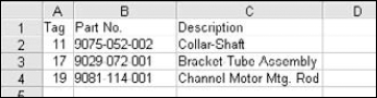
Create the worksheet shown in Figure 27.12. Adjust the width of the columns to fit the data.
In the spreadsheet application, choose File
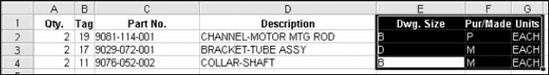
Open your spreadsheet application and open
ab27-c.xlsfrom the DVD. Select the data in the last three columns, as shown in Figure 27.14. Copy it to the Clipboard.Leave your spreadsheet open and click the AutoCAD or AutoCAD LT button on the Windows task bar. Choose Home tab
The spreadsheet is inserted as a table object, but is very small. Click outside the table to close the In-Place Text Editor. Zoom in on the table. Click the lower-right corner of the table and drag its handle down and to the right until the table is the same height as the spreadsheet to its left.
Click inside the upper-left cell, press Shift, and click inside the lower-right cell. Display the Properties palette (Ctrl+1) and change the Text Height to .6800. Change the Text Style to WMF-Arial0. (This text style was created when you imported the spreadsheet, to match the original text in the spreadsheet.) Change the Alignment to Middle Center.
Choose Home tab
Note that the first row of data has a "P" in the
Pur/Madecolumn. Return to your spreadsheet and change cell F2 (which now says P) to M, and press Enter. Go back to your drawing and note that the P has changed to an M. Because the data are linked, any changes made to the spreadsheet are updated in your drawing.Save your drawing. Close your spreadsheet program without saving the change that you made.
In this chapter, you read about the following:
Importing and exporting other file formats, including both vector and bitmap (raster) formats
Working with DXF files
Managing images and controlling their display
Pasting, linking, and embedding objects into your drawing
The next chapter discusses how to integrate AutoCAD and AutoCAD LT with the Internet.