Conduction laser welding
Abstract:
Laser welding has two different operational regimes: conduction and keyhole welding. The key difference between these two modes is the power density applied to the welding area. Conduction takes place when the intensity is not sufficient to cause boiling. In keyhole mode, the intensity used is high enough to cause vaporisation and create a keyhole in the melt pool. The current definition of conduction laser welding mode based on power density is discussed. Some studies focused on conduction laser welding are also discussed, emphasising the effect of beam diameter in this mode. Finally, an overview of some of the most relevant applications of conduction laser welding in industry is presented. This chapter not only emphasises how good and diverse the applications of this welding mode are, when compared to keyhole laser welding, but also helps in understanding the flexibility of this welding process.
6.1 Introduction: comparison between keyhole and conduction laser welding
There are two main operational regimes in laser welding: keyhole and conduction laser mode.1,2 The main difference between these two modes is the power density used. In this chapter the focus will be on the process differences between these two welding modes, such as productivity, stability, spatter and others. The characteristics of keyhole laser welding led industry to focus on this mode. The main characteristics of keyhole laser welding are deep penetration, the small heat affected zone and the high productivity of this process.1 However, keyhole welding also possesses several problems that may lead to high levels of porosity, instabilities, spatters (Fig. 6.1) and other weld defects.1,3–5 For example, keyhole laser welding of aluminium shows numerous problems. The high thermal conductivity, low boiling point elements and low viscosity are just some of the characteristics of aluminium alloys that lead to defects such as loss of alloy elements, degradation of mechanical properties, excessive porosity and blowholes, and to an unstable process when keyhole laser welding.4,6–9 Ion showed in a review paper how different aluminium series behave when keyhole laser welded.8 For example, when laser welding a 5000 series there is significant vaporisation of magnesium. This vaporisation creates fluctuations in the keyhole mechanism, which affects the properties of the weld. This results in coarse porosity and in an irregular weld beam. Also, the magnesium loss to the vaporisation reduces solid solution hardening and degrades the tensile strength and ductility in comparison with the base material.8 In terms of the laser system, keyhole laser welding requires a relatively good beam quality.9
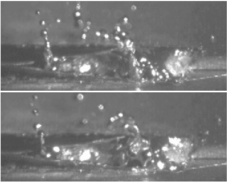
6.1 High-speed images of a blowout event that originates spatter in keyhole laser welding.13
On the other hand, conduction laser welding shows several advantages. This welding process can be a viable alternative to keyhole laser and to arc welding. It is a stable process which allows better control of the heat delivered to the workpiece. The use of large beams in this mode reduces fit-up problems and the laser system used does not require a high beam quality.9 One of the disadvantages attributed to conduction mode welding was that the penetration depth of the welds was small, around 2 mm.10 Recent work has shown that it is possible to obtain high penetration depth (see Fig. 6.2), using conduction mode welding and that this penetration is related to the parameters chosen.9
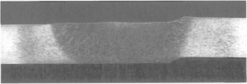
6.2 Conduction laser weld with 6.35 mm of penetration.23
One of the disadvantages of conduction mode laser welding is the coupling efficiency of this process, especially when welding high reflective materials. Coupling is basically the percentage of energy that comes from the laser that is absorbed by the material. In keyhole laser welding, most of the beam is absorbed; however, in conduction the amount of laser beam absorbed by the material is smaller. For example, when laser welding stainless steel, the absorption of the laser beam in conduction mode is around 15% while in keyhole mode it jumps to 65%.11 The increase of the absorption is a good indicator of the formation of a keyhole due to the increase of the coupling.
However, the values of coupling depend on several factors, such as the wavelength of the laser, the surface finishing, the material and the thickness of the welded material.11,12 Some studies have been made in measuring the coupling for different materials. While for steel the coupling was between 20 and 90%, in aluminium it varied from 10 to 80%.12,13
A brief comparison between conduction and keyhole mode is presented in Table 6.1. Due to the differences in the welds obtained and in the welding process itself, conduction laser welding tends to increase the applications of laser welding and not ‘compete’ with keyhole laser welding.
Table 6.1
Advantages and disadvantages of conduction and keyhole laser welding
| Process | Advantages | Disadvantages |
| Keyhole laser welding | Low heat input which originates low distortion Deep penetration welds with a big aspect ratio High productivity |
Unstable process High levels of porosity Big amount of spatter Loss of alloy elements Degradation of mechanical properties Requires a laser system with a relatively good beam quality |
| Conduction laser welding | No vaporisation takes place – which means no porosity, no cracks and no undercut on the welds No spatter during welding Stable process with control of the heat input Good gap bridging ability due to the large beams used Does not require a laser system with a high quality beam |
Low coupling efficiency Slow process High heat input which means higher distortion |
6.2 The transition between conduction and keyhole mode
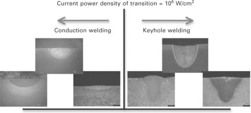
The major difference between conduction and keyhole welding is the power density applied to the welding area. When the power density used is insufficient to cause boiling, the weld occurs in conduction mode. The alternative to this mode is keyhole mode welding, where the power density is sufficient to provide evaporation and open a hole in the melt pool. Despite different studies of these two welding modes, the boundaries between them are not clear in terms of processing parameters. Often it is considered that conduction welding occurs when the power density is lower than 106 W/cm2.14–16 This value is completely independent of the welding speed or the beam diameter used. It is also sometimes considered that conduction welding occurs when the value of the laser power is low, of the order of 1 kW; at this low value of power, the power density at the surface of the welded material is limited. Despite these different definitions for conduction laser welding, there is one fundamental point where there seems to be agreement, which is that conduction welding occurs when the vaporisation of the material is insignificant1,15 or when the power density is not enough to cause boiling.14 Another definition for conduction laser welding mode is that it shows an aspect ratio smaller than 0.5.17 Nevertheless, these definitions have one thing in common: they do not take into account other welding parameters such as beam diameter and welding speed. A schematic of the current definition of conduction and keyhole laser welding is shown in Fig. 6.3.
There are not that many studies focused on the transition between conduction and keyhole laser welding mode. The following paragraphs review the relevant work done in this area.
Beyer et al. studied the absorption of a laser-induced plasma during laser processing.18 The main focus of this paper was not the study of the transition between conduction and keyhole mode. However, a relation between power density, pulse duration and beam radius and the threshold power density for vaporisation was established, mainly in the region of laser processing (between 1 and 100 ms of interaction time) where the power density necessary for vaporisation is dependent on the beam radius and interaction time (Fig. 6.4). This part of the paper relied on an analytical equation that represents the surface at the beam centre for Gaussian beams.19 However, no final conclusion was drawn regarding the transition between conduction and keyhole laser welding.
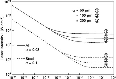
6.4 Laser power density necessary to reach vaporisation temperature at the centre of the beam as function of time.18
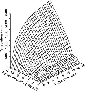
Liu et al. and Weckman et al. studied the effects of process variables on pulsed laser welding, for stainless steel and aluminium, respectively (Fig. 6.5). They concluded that the power density at which keyhole mode starts is independent of the pulse duration after a certain value of pulse time. However, there was a change in the power density at which a keyhole starts depending on the material. This was, in part, in agreement with what was previously considered to be true. However, the threshold power density for when the keyhole starts for stainless steel was 4 GW/m2 and 10 GW/m2 for aluminium (different from the 106 W/cm2 mentioned previously) and so dependent on the material.20,21
Zhang et al. studied the transition between the different laser welding modes. In this work, it was concluded that laser power, focal position and travel speed will influence the welding mode. However, the double-U curve described is difficult to apply in a broader parameter range.22
Using a finite-element model, Buvanashekaran et al. evaluated the welding mode based on different energy levels. The authors concluded that there was a range of power densities where conduction mode takes place. At a welding speed of 1,000 mm/min, it was concluded that the transition from conduction to keyhole mode took place with 400 W of laser power.23 In this work, despite concluding that there was a range of power densities where conduction mode takes place, no relation between the parameters and the welding mode was made and just a set of parameters was given as an example of where conduction would transit to keyhole mode.
Sibillano et al. used a real-time monitoring of the plasma, formed during the different welding regimes, to identify the welding mode.24 However, this study showed no relation between the welding parameters and the welding mode. It also relied on the definition that the welding mode is defined based on the power density used (> 106 W/cm2 for keyhole and < 106 W/cm2 for conduction).
Nakamura et al. combined the optical and acoustic emissions from a laser irradiated spot. It was stated that, depending on the material, for 3 kW of laser power there was a welding speed range where conduction laser welding took place.17 However, the identification of the welding mode was based on the ratio between penetration and width. Also no relation was established between the welding parameters and the welding mode.
All these works do not relate the transition from conduction to keyhole to the process parameters and how the process parameters influence the transition between conduction and keyhole. In some points, the works even show different conclusions. For example, while some studies show that there is a sharp transition between conduction and keyhole regime, other works identified a regime between conduction and keyhole. The presence of two or three welding modes in laser welding is also a common difference in some laser modelling papers. The following paragraphs present some examples of those differences.
Zhang et al. identified three kinds of laser welding process: stable heat conduction welding, stable deep penetration welding and unstable mode welding. The existence of this unstable mode welding or transition mode was attributed to thermal focusing or to an unsuitable selection of welding parameters.22 The existence of this unstable mode, which was attributed to welding mode fluctuation, was previously identified by Chen et al.25 and Zhang et al.26
The existence of just conduction mode regime and keyhole mode regime in PW laser welds was shown by the use of a model. The model shown by Semak et al.27 relates metal displacement to the vaporisation recoil pressure (Fig. 6.6). In this model the melt displacement happens when the vaporisation recoil pressure accelerated the melt created in the fusion zone allowing this molten material to reach the edge of the molten pool. In this model it was possible to identify three different thresholds: one for when drilling starts to take place, another for when displacement starts to happen and another for melting. In this model, Semak et al. observed that at energy levels lower than the drilling threshold and higher than the displacement threshold was where the keyhole mode regime took place. On the other hand, it was assumed that the regime between the displacement threshold and the melting threshold was when the conduction mode regime took place.27 In this work no regime was identified between conduction and keyhole regime. The model shown by Resch and Kaplan also considers two welding modes, conduction and keyhole laser welding.28
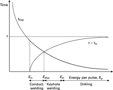
6.6 Identification of the different welding regimes, conduction and keyhole, in pulsed laser welding by Semak et al.27
Based on the drilling model, Colegrove et al. identified three different regimes in pulsed laser welding.29 They were conduction mode, mixed mode and keyhole mode regime (Figs 6.7 and 6.8). The presence of these three regimes had also been shown previously by Steen14 and Ahmed.30
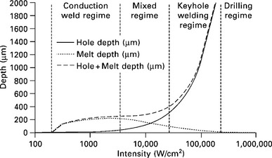
6.7 Identification of three welding modes in pulsed laser welding.29
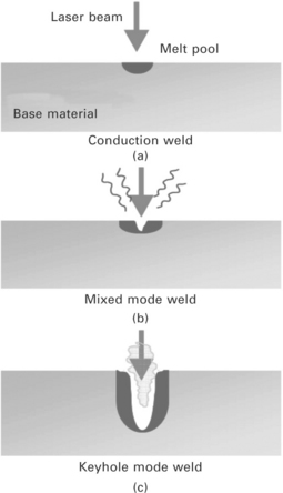
6.8 The three welding regimes in pulsed laser welding.29
Buvanashekaran et al. identified three laser welding modes that are determined by the laser power and welding speed. Although, the authors established that the transition between conduction and keyhole for a 1,000 mm/min welding speed would occur at 400 W beam power, if a mode between conduction and keyhole was identified these values should represent the end of conduction or the beginning of keyhole mode and not the transition between these two modes (Fig. 6.9).23
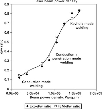
6.9 Identification of the three welding modes by Buvanashekaran et al.23
Sibillano et al. also identified a mixed mode in laser welding. The authors defined this regime as having properties of both conduction and keyhole. This was noticed when the power density was just over the threshold for keyhole mode and so it was assumed to be caused by unstable keyhole formation.24
Based on the literature review, it is clear that the threshold of conduction laser welding mode is inaccurate and does not take into account the process parameters. An analytical approach to the transition between conduction and keyhole mode would also be possible. However, most of the analytical models found19 are not dependent on the beam diameter or on the welding speed when the boundary conditions for determining the temperature at the centre of the laser beam are applied. The number of regimes and the transition between conduction and keyhole mode have been studied by several authors and progress made, though further research on this topic might clarify some of the aspects mentioned above.
6.3 Conduction laser welding
Conduction welding mode is mainly controlled by convection and conduction. In the specific case of laser welding at high intensities, it is normal to form a temperature gradient that itself will lead to surface tension also known as Marangoni convection. The literature about Marangoni convection is extensive; research by Zhao et al.,31 Limmaneevichitr and Kou32–34 and Chan et al.35 are just a few examples. This convection is responsible for the geometry of the laser melt pool, e.g. its shape and aspect ratio. The composition of the melt pool during conduction laser welding is also influenced by convection, mainly due to the fact that convection is responsible for the mixing of material that happens during the laser welding process.36 In this mode the energy absorbed at the surface and by thermal conduction is transferred to the interior of the material (Fig. 6.10).14
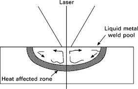
6.10 Schematic of conduction laser welding.14
Conduction welding can be a viable alternative to keyhole welding mainly because it is a very stable process and easier to obtain high quality welds free of pores and spatter.37 This mode takes place when the vaporisation of the material is insignificant, in other words, when the thermal power density is not high enough to cause boiling.38 Another advantage of conduction laser welding is that it can be made with a significantly low laser cost, because it does not require a high beam quality or very high power.15
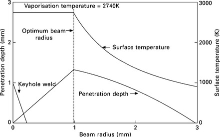
Some studies, based on modelling and followed by experimental validation, have shown that there is an optimum beam diameter. This means that for a certain value of power and travel speed there is a specific beam diameter in which the penetration is maximum. This phenomenon occurs when, by increasing the beam diameter, the temperature at the surface remains at vaporisation temperature. In other words, when welding in conduction mode, a progressive increase in the spot size will result in an increase in penetration depth as long as the temperature at the surface of the workpiece is maintained at boiling temperature. However, when the optimum beam diameter is achieved, the increase of the spot size will result in a decrease in the penetration depth because by increasing the spot size the temperature at the surface will decrease, which means it will be lower than the boiling temperature.9,38
Based on this principle, Bardin et al. were able to control the conduction mode welding process by thermal measurements (Fig. 6.11). Controlling the temperature of the welding process, keeping it just below the boiling point of the material, allowed the maximum penetration to be obtained. It was also noticed that when the temperature went over the boiling temperature, the presence of porosity was clear.38
Despite the fact that not many investigations have been carried out on conduction laser welding, some pioneer studies have been made in this welding mode and are reviewed in the following paragraphs.
One of the first works on conduction laser welding was by Esposito et al.39 An evaluation of the welding parameters based on a theoretical model and experimental data was shown. One of the conclusions was that the temperature was controlled by the beam diameter and that the rise in temperature over the melting point would reduce the process efficiency. It was also concluded that the welding speed was related to the desired width of the weld and that the choice of the beam diameter was made by selecting a beam diameter that would provide the better coupling.39 However, in this work the relation between welding speed, beam diameter and laser power was not fully discussed and evaluated. The principles behind this work were correct. The issue was how it related the choice of the beam diameter to the coupling and not to the control of the maximum temperature at the surface of the weld pool (as shown previously).
Paul and Debroy simulated the weld pool shape and the peak temperature based on numerical solutions of Navier2013Stokes equation and the equation of energy conservation. The results showed good approximation to the experimental data; however, no evaluation of the welding parameters on the weld shape was made. They also showed that the temperature achieved in the laser-material interaction was close to the boiling point of the material. This emphasises that in this welding mode the vaporisation of material is insignificant.40 Zhao and Debroy also evaluated the composition change in conduction mode laser welding of aluminium. They noticed that when vaporisation takes place in conduction mode, it is confined to a very small region under the laser beam. This vaporisation takes place due to a slight increase in the temperature over the boiling point of the aluminium. In this work, they evaluated that the welding speed and the laser power had no influence on the composition of the welded metal.41 De and Debroy developed a model based on heat transfer and fluid flow for conduction mode spot welding. In this model they were able to optimise the laser beam absorptivity, effective thermal conductivity and the effective diffusivity based on a small number of experiments.42
More work has been carried out on modelling conduction laser welding. Bag et al. and Trivedi et al. studied the effect of power and on-time on the weld pool shape, using a finite element model with an adaptive heat source.43,44 Tsai and Kannatey-Asibu implemented a model suitable for feedback control based on a 2D heat flow model.45 A numerical and experimental investigation was made to determine the importance of sulphur content and welding parameters on the fluid flow, heat transfer and shape of the welds obtained using a pulsed laser in conduction mode.46 Pitscheneder et al. also developed a model to study the behaviour of solid precipitates.47 The heat conduction in the weld pool and the convections phenomena were analysed by Bos and Chen, allowing a prediction of the pool geometry based on the parameters used during the welding process.48 Conduction mode welds in different materials were carried out by Russo in order to allow a numerical and experimental investigation of the weld-pool surface phenomena.49 Tobar et al. developed a three-dimensional numerical model to study aluminium laser welding in conduction mode and to evaluate the use of different surface treatments in order to increase the laser absorption. The authors concluded that in conduction mode the heat transfer is controlled by convection and not by conduction and that the flow of liquid material is caused by surface tension.50 None of the works mentioned here related the influence of each process parameter and how they will influence conduction laser welding. Most of the work was actually based on modelling just using some welded samples as the starting point. This means that despite the models showing a good relation to the experimental data, there is no analysis over a range of parameters, which should include laser power, welding speed and beam diameter.
An interesting study has been carried out by Kell et al.51 They evaluated the use of different beam profiles in conduction laser welding, maintaining the same energy density for the different beam profiles. The beam profiles used were: Gaussian, top-hat, rugby post and peaked edge line.51 The conclusions were more related to the microstructure obtained by each beam profile and on the welded profile. However, based on Fig. 6.12, the assumption of the paper that all the welds were made in conduction mode does not seem to be completely correct. While the weld profile obtained using the peaked edge line is clearly in conduction mode, the weld profiles obtained using the other beams might not be. The reason might be related to the irradiance distribution obtained in all the profiles, which in the case of the peaked edge line might be more suitable for conduction laser welding. This paper is a good example of the lack of clarity in the definition of conduction laser welding.
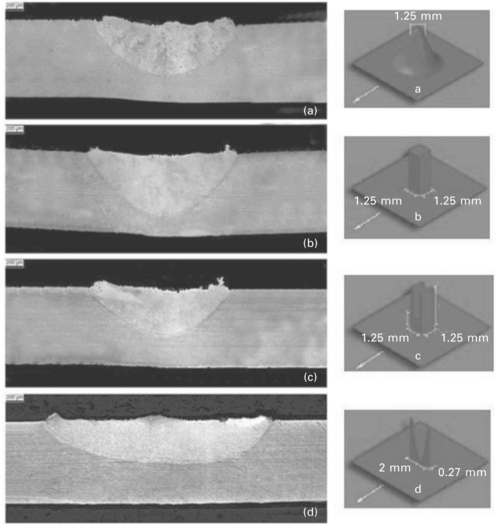
6.12 Micrographs and respective beam profiles of the welds obtained: (a) Gaussian, (b) top-hat, (c) rugby post and (d) peaked edged line.51
6.4 Applications of conduction laser welding
The number of applications that use conduction laser welding is very low when compared to the number of applications that use keyhole laser welding. Even the applications that used conduction laser welding do not mention this welding mode. In these cases, a closer look at the welding parameters proves that this mode was used. One of the first applications of conduction laser welding goes back to 1970, when it was used to weld thermocouples to a sample container carried by the Apollo space shuttle.51 Other applications included welding seals of electronic packages53 and welding non-precious dental alloys.54
One of the applications where conduction laser welding has been most used is in welding aluminium alloys. The problems in using keyhole mode in laser welding of aluminium alloys can be overcome by using conduction laser welding. Some examples of the application of conduction laser welding in aluminium are the work done by Morgan and Williams,9 by Okon et al.37 and by Sanchez-Amaya et al.16,55 The results showed that by using conduction mode laser welding, it is possible to obtain welds free of pores and of cracks, two defects normally associated with laser welding of aluminium. In terms of the penetration achieved, Okon et al. were able to obtain full penetration in 3 mm thick AA5083,37 Sanchez-Amaya et al. were also able to obtain full penetration on 3 mm thick AA5083 and 2.3 mm penetration on AA6082 (Fig. 6.13) while Morgan and Williams were able to achieve full penetration on 6.35 mm thick AA2024.9
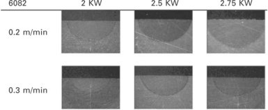
6.13 Some examples of conduction laser welding in AA6083 with different power and welding speeds.55
Another application of conduction laser welding is in joining of dissimilar materials.56–58 One of the most common combinations of materials is aluminium to steel weld. Due to the difficulty of this type of weld, several studies using resistance spot welding arc welding brazing and friction stir welding have been carried out. However, in recent years laser welding has been introduced as an alternative for welding steel to aluminium. Studies using keyhole welding in order to join aluminium to steel were made59 but with limited success. Nevertheless, studies using conduction laser welding have shown very good results.60–62 The advantage of using conduction laser welding in this application is related to the stability of the process that allows a better control of the temperature in the interaction area between the aluminium and the steel.61
The use of conduction mode welding on magnesium alloys has also been assessed.63,64 It was possible, using conduction welds, to obtain a weld with less porosity, fewer cracks and with a smaller crater. However, in these works, it is unclear if the welds were made in ‘pure’ conduction mode. The profiles shown by the welds resemble a conduction mode. But the presence of a high vaporisation in the welding process raises some issues about the use of conduction laser welding.64 Even so, the use of an ‘almost’ conduction mode weld has shown encouraging results in laser welding of magnesium alloys.
The introduction of new high power diode lasers will increase the use of conduction laser welding.65 mainly because the use of this type of laser will solve one of the biggest issues in conduction laser welding, the low beam absorption, due to the wavelength of these lasers. Applications like aesthetical welds, brazing, cladding, soldering and polymer welding that are normally done in conduction mode will increase.66 Figure 6.14 shows some examples of conduction laser welding using a diode laser.

6.14 Kitchen sink weld (left) and powder deposition (right). 66
The use of high power diode lasers allows the use of conduction laser welding in materials like aluminium and titanium55,67 without any concerns related to the absorption of the laser beam by the material. Abe et al. showed some applications using this type of laser.68 However, in no part of this work is conduction laser welding mode mentioned. A closer look at the welds obtained (Fig. 6.15), and at the characteristics of the welding process (no spatter and no plasma), it was clear that the welds were made in conduction mode. Funada69 and Abe68 also used conduction laser welding on thin film with good results.69-70
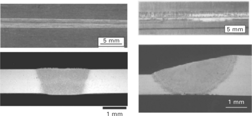
6.15 Examples of conduction laser welding using a high power diode laser.68
Bassani et al. also used diode laser source to study the effect of process parameters on laser welding of an aluminium metal matrix composite reinforced with SiC particles. In this work a comparison was made between using a CO2 laser to create a weld in keyhole mode, while a diode laser was used to produce a conduction mode weld (Fig. 6.16). The welds obtained in conduction mode showed a good metallurgical quality and the formation of Al4C3 was reduced considerably when compared to the welds made under keyhole mode.71

6.16 Some examples of diode laser welding, in conduction mode, of A359/SiC metal matrix composite.71
The application of a diode laser in welding titanium was also assessed by Block et al.72 In this work no reference to conduction laser welding was made but the profile of the welds and the parameters used indicate that the welds were made in conduction mode (Fig. 6.17). Diode lasers have also been used in laser welding magnesium alloys with good results, which include the increased resistance to corrosion and wear.73 Once again there is no reference to conduction mode laser welding, but the profiles shown in Fig. 6.18, mainly the low aspect ratio, indicate that conduction was the welding mode used.74
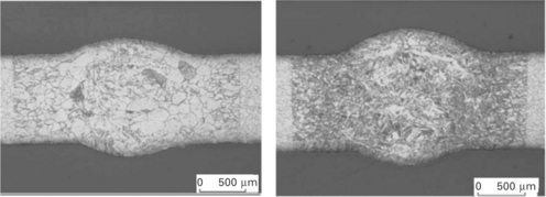
6.17 Laser filler weld seams on titanium.72

6.18 Macrographs of laser welded AZ61 magnesium alloy.74
These last applications emphasise how the appearance of new high power diode lasers will increase the use of conduction mode laser welding. With the number of applications of conduction laser welding increasing, it is important to better understand the limits and the process of conduction laser welding.
However, conduction mode is not only used in laser welding. Another application is laser cladding, also known as laser metal deposition.75,76 Despite in the literature related to laser cladding there being few references to conduction mode, based on the parameters used, mainly the low power densities, the properties of the cladding process (no spatter and stable process) and the properties of the clad (free of pores), it is possible to conclude that the process is normally done in conduction mode. Some studies mention that the power densities used are below the threshold for plasma formation, which means below the start of vaporisation,76 emphasising the fact that conduction mode is used in laser cladding. Contrary to the applications of conduction mode in laser welding, the number of applications of laser cladding is extensive.77–81 These types of applications show how, very often, conduction mode laser welding is mistaken for keyhole laser welding. As mentioned previously, the number of applications that use laser cladding is vast and it is common to see laser cladding parameterisation as if it was done in keyhole mode (Fig. 6.19).81,82
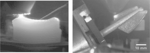
6.19 Manufacturing of a 3D block of a Ti-47Al-2Cr-2Nb (left)82 and manufacturing of a Cp-Ti tube (right).81
Conduction mode laser welding is also used in welding plastics. This process is sometimes referred to as laser transmission welding.83,84 It requires a very controllable heat delivery to the workpiece and a very stable welding process.
An innovative application of conduction mode is in underwater laser beam welding. This technique is used in the nuclear industry for repair/maintenance applications. In this application, which is a laser cladding process and not a laser welding process, the heat input to the base material needs to be extremely well controlled. The principle behind this application is to deposit a cladding layer in order to avoid crack propagation in the base material (Fig. 6.20). It is the stability of the process, the control of the heat delivered to the workpiece and the quality of the welds obtained in this welding mode that trigger its increasing application.

6.20 Schematic of underwater laser beam welding (left), underwater laser beam welding deposit (right).85
6.5 References
1. Ready, J. F., Farson, D. F. LIA handbook of laser materials processing. Orlando, FL: Laser Institute of America, 2001.
2. Bass, M. Laser materials processing. New York: Elsevier Science; 1983.
3. Lima, M. S. F., Riva, R., De Oliveira, A. C., Siqueira, G. R., Laser beam welding aerospace aluminum using fiber lasers. Proceedings of SPIE. The International Society for Optical Engineering, Lisbon, 2009.
4. Paleocrassas, A. G. and J. F. Tu, Inherent instability investigation for low speed laser welding of aluminum using a single-mode fiber laser. Journal of Materials Processing Technology. 210(10): 1411–1418
5. Eriksson, I., Kaplan, A. F. H. 28th International Congress on Applications of Lasers and Electro-Optics, Congress Proceedings. Evaluation of laser weld monitoring – A case study, in ICALEO 2009. 2009. [Orlando, FL].
6. Cao, X., Wallace, W., Poon, C., Immarigeon, J. P. Research and progress in laser welding of wrought aluminum alloys. I. Laser welding processes. Materials and Manufacturing Processes. 2003; 18(1):1–22.
7. Hu, B., Richardson, I. M. Autogenous laser keyhole welding of aluminum alloy 2024. Journal of Laser Applications. 2005; 17(2):70–80.
8. Ion, J. C. Laser beam welding of wrought aluminium alloys. Science and Technology of Welding and Joining. 2000; 5(5):265–276.
9. Morgan, S., Williams, S., Hybrid laser conduction welding. 55th Annual Assembly of International Institute of Welding. 2002. [Copenhagen, Denmark].
10. Tam, S. C., Williams, R., Yang, L. J., Jana, S., Lim, L. E. N., Lau, M. W. S. A review of the laser processing of aircraft components. Journal of Materials Processing Tech.. 1990; 23(2):177–194.
11. Nath, A. K., Sridhar, R., Ganesh, P., Kaul, R., Laser power coupling efficiency in conduction and keyhole welding of austenitic stainless steel. Sadhana – Academy Proceedings in Engineering Sciences. 2002. [27(Part 3)].
12. Weston, J. W., E. R. Wallach, Coupling for laser welds in aluminium alloys. Department of Materials Science and Metallurgy, University of Cambridge.
13. Mallory, L. C., Orr, R. F., Wells, W., Effect of anodizing on laser welding of aluminium. Laser Materials Processing III. 1989.
14. Steen, W. M. Laser material processing, 3rd ed. New York: Springer; 2003.
15. Ion, J. C. Laser processing of engineering materials: principles, procedure and industrial application. Oxford: Butterworth-Heinemann; 2005.
16. Sanchez-Amaya, J. M., Delgado, T., De Damborenea, J. J., Lopez, V., Botana, F. J. Laser welding of AA 5083 samples by high power diode laser. Science and Technology of Welding and Joining. 2009; 14(1):78–86.
17. Nakamura, S., Sakurai, M., Kamimuki, K., Inoue, T., Ito, Y. Detection technique for transition between deep penetration mode and shallow penetration mode in CO2 laser welding of metals. Journal of Physics D: Applied Physics. 2000; 33(22):2941–2948.
18. Beyer, E., Bakowsky, L., Loosen, P., Poprawe, R., Herziger, G., Development and optical absorption properties of a laser induced plasma during CO2-laser processing. Proceedings of SPIE – The International Society for Optical Engineering. SPIE, Linz, Austria, 1984.
19. Carlsaw, H. S., Jaeger, J. C., Conduction of heat in solids. 2nd ed. Clarendon Press, Oxford, 1959.
20. Liu, J. T., Weckman, D. C., Kerr, H. W. The effects of process variables on pulsed Nd:YAG laser spot welds: Part I. AISI 409 stainless steel. Metallurgical Transactions B. 1993; 24(6):1065–1076.
21. Weckman, D. C., Kerr, H. W., Liu, J. T. The effects of process variables on pulsed Nd:YAG laser spot welds: Part II. AA 1100 aluminum and comparison to AISI 409 stainless steel. Metallurgical and Materials Transactions B: Process Metallurgy and Materials Processing Science. 1997; 28(4):687–700.
22. Zhang, X., Chen, W., Ren, J., Huang, G., Zhang, H., Laser welding mode transition and influence of thermal focusing on mode transition. Proceedings of SPIE – The International Society for Optical Engineering. 1996. [Beijing, China].
23. Buvanashekaran, G., Siva, N. Shanmugam, K. Sankaranarayanasamy, and R. Sabarikanth, A study of laser welding modes with varying beam energy levels. Proceedings of the Institution of Mechanical Engineers, Part C: Journal of Mechanical Engineering Science. 2009; 223(5):1141–1156.
24. Sibillano, T., Ancona, A., Berardi, V., Schingaro, E., Basile, G., LugarÃ, P. M. Optical detection of conduction/keyhole mode transition in laser welding. Journal of Materials Processing Technology. 2007; 191(1–3):364–367.
25. Chen, W., Zhang, X., Ren, J. Study of welding mode transition and stability of welding process in high laser welding. Chinese Journal of Lasers. 23(7), 1996.
26. Zhang, X., Chen, W., Ren, J., Effects of processing parameters on mode and stability of laser welding. Photonics West’ 1996; 96:.
27. Semak, V. V., Knorovsky, G. A., MacCallum, D. O. On the possibility of microwelding with laser beams. Journal of Physics D: Applied Physics. 2003; 36(17):2170–2174.
28. Resch, M., Kaplan, A. F. H. Heat conduction modelling of laser welding. Lasers in Engineering. 1998; 7(3–4):229–240.
29. Colegrove, P., Simiand, P. E., Varughese, A., Williams, S., Yapp, D., Evaluation of a drilling model approach to represent laser spot microwelding. ASM Proceedings of the International Conference: Trends in Welding Research. 2009. [Pine Mountain, GA].
30. Ahmed, N. New developments in advanced welding. Boca Raton, FL: CRC Press; 2005.
31. Zhao, C. X., Kwakernaak, C., Pan, Y., Richardson, I. M., Saldi, Z., Kenjeres, S., Kleijn, C. R. The effect of oxygen on transitional Marangoni flow in laser spot welding. Acta Materialia. 2010; 58(19):6345–6357.
32. Limmaneevichitr, C., Kou, S. Visualization of Marangoni convection in simulated weld pools. Welding Journal. 2000; 79(5):126. [–s].
33. Limmaneevichitr, C., Kou, S. Experiments to simulate effect of Marangoni convection on weld pool shape. Welding Journal. 79(8), 2000.
34. Limmaneevichitr, C., Kou, S. Visualization of Marangoni convection in simulated weld pools containing a surface-active agent. Wetding Journal. 2000; 79(11):324. [-s].
35. Chan, C. L., Mazumder, J., Chen, M. M. Three-dimensional axisymmetric model for convection in laser-melted pools. Materials Science and Technology. 1987; 3(4):306–311.
36. Cary, H. B. Modern welding technology, 2nd ed. Englewood Cliffs, NJ: Prentice Hall; 1989.
37. Okon, P., Dearden, G., Watkins, K., Sharp, M., French, P., Laser welding of aluminium alloy 5083. ICALEO 2002 – 21st International Congress on Applications of Laser and Electro-Optics, Congress Proceedings. 2002. [Scottsdale, AZ].
38. Bardin, F., Morgan, S., Williams, S., McBride, R., Moore, A. J., Jones, J. D. C., Hand, D. P. Process control of laser conduction welding by thermal imaging measurement with a color camera. Applied Optics. 2005; 44(32):6841–6848.
39. Esposito, C., Duarelio, G., Cingolani, A. On the conduction welding process of steels with CO2 lasers. Optics and Lasers in Engineering. 1982; 3:139–151.
40. Paul, A., Debroy, T. Free surface flow and heat transfer in conduction mode laser welding. Metallurgical Transactions B. 1988; 19(6):851–858.
41. Zhao, H., Debroy, T. Weld metal composition change during conduction mode laser welding of aluminum alloy 5182. Metallurgical and Materials Transactions B: Process Metallurgy and Materials Processing Science. 2001; 32(1):163–172.
42. De, A., Debroy, T. Improving reliability of heat and fluid flow calculation during conduction mode laser spot welding by multivariable optimisation. Science and Technology of Welding and Joining. 2006; 11(2):143–153.
43. Bag, S., Trivedi, A., De, A. Development of a finite element based heat transfer model for conduction mode laser spot welding process using an adaptive volumetric heat source. International Journal of Thermal Sciences. 2009; 48(10):1923–1931.
44. Trivedi, A., Bag, S., De, A. Three-dimensional transient heat conduction and thermomechanical analysis for laser spot welding using adaptive heat source. Science and Technology of Welding and Joining. 2007; 12(1):24–31.
45. Tsai, F. R., Kannatey-Asibu, E., Jr. Modeling of conduction mode laser welding process for feedback control. Journal of Manufacturing Science and Engineering, Transactions of the ASME. 2000; 122(3):420–428.
46. Pitscheneder, W., Numerical and experimental investigation of conduction-mode laser weld poolsCerjak H. E., ed. Mathematical Modeling of Weld Phenomena. 1998; 4:.
47. Pitscheneder, W., Hong, T., Debroy, T., Ebner, R., Mundra, K., Benes, R. Experimental and numerical investigation of transport phenomena in conduction mode weld pools. Welding in the World. 2000; 44(6):25–36.
48. Bos, J. A., Chen, M. A., On the prediction of weld pool size and heat affected zone in Shallow-Pool Welding. Transport Phenomena in Materials Processing and Manufacturing ASME. 1996:336.
49. Russo, A. J. Two-dimensional modelling of conduction-mode laser welding. L. I. A.. 1984; 44:8–15. [(ICALEO)].
50. Tobar, M. J., I. M. Lamas, A. Yáñez, J. M. Sánchez-Amaya, Z. Boukha, and F. J. Botana, Experimental and simulation studies on laser conduction welding of AA5083 aluminium alloys. Physics Procedia. 5(2): 299–308
51. Kell, J., Tyrer, J., Higginson, R., Thomson, R., Jones, J., Noden, S., Holographic diffractive optical elements allow improvements in conduction laser welding of steels. ICALEO. 2006; 2006:.
52. Moorhead, A. J., Turner, P. W. Welding a thermocouple gauge to Apollo lunar sample return containers. Welding Journal. 1970; 49:15–21.
53. Emerson, W. F. Laser-beam welding seals electronic packages. Welding Design and Fabrication. 1996; 69(4):43–44.
54. Bertrand, C. The laser welding technique applied to the non precious dental alloys procedure and results. British Dental Journal. 2001; 190(5):255–257.
55. Sanchez-Amaya, J. M., Delgado, T., Gonzãlez-Rovira, L., Botana, F. J. Laser welding of aluminium alloys 5083 and 6082 under conduction regime. Applied Surface Science. 2009; 255(23):9512–9521.
56. Sepold, G., Schubert, E., Zerner, I., Laser beam joining of dissimilar materials. IIW. 1999. [Lisbon].
57. Xiao, R., Dong, P., Chen, K., Laser beam welding of dissimilar materials. ICALEO 2009 – 28th International Congress on Applications of Lasers and Electro-Optics, Congress Proceedings. 2009. [Orlando, FL].
58. Theron, M., Van Rooyen, C., Ivanchev, L. H., CW Nd:YAG laser welding of dissimilar sheet metals. 26th International Congress on Applications of Lasers and Electro-Optics, ICALEO 2007 – Congress Proceedings. 2007. [Orlando, FL].
59. Sierra, G., Peyre, P., Deschaux-Beaume, F., Stuart, D., Fras, G. Steel to aluminium key-hole laser welding. Materials Science and Engineering A. 2007; 447(1–2):197–208.
60. Sierra, G., Peyre, P., Deschaux, F. Beaume, D. Stuart, and G. Fras, Galvanised steel to aluminium joining by laser and GTAW processes. Materials Characterization. 2008; 59(12):1705–1715.
61. Kreimeyer, M., Wagner, F., Sepold, G., Development of a combined joining-forming process for aluminum-steel joints. ICALEO 2004 – 23rd International Congress on Applications of Laser and Electro-Optics, Congress Proceedings. 2004. [San Francisco, CA].
62. Kreimeyer, M., Sepold, G., Processing of laser joined aluminum-steel tailored blanks in overlap and butt joint configuration. ICALEO 2002 – 21st International Congress on Applications of Laser and Electro-Optics. 2002. [Scottsdale, AZ].
63. Zhu, J., Li, L., Liu, Z. CO2 and diode laser welding of AZ31 magnesium alloy. Applied Surface Science. 2005; 247:300–306.
64. Min, D., J. Shen, S. Lai, J. Chen, N. Xu, and H. Liu, Effects of heat input on the low power Nd:YAG pulse laser conduction weldability of magnesium alloy AZ61. Optics and Lasers in Engineering. 49(1): 89–96
65. Williams, S., Scott, G., Calder, N. Direct diode laser welding of aerospace alloys. Laser Opto. 2001; 33:50–54.
66. Bachmann, F. Industrial applications of high power diode lasers in materials processing. Applied Surface Science. 2003; 208–209:125–136.
67. Caiazzo, F., Curcio, F., Daurelio, G., Memola Capece Minutolo, F. Ti6Al4V sheets lap and butt joints carried out by CO2 laser: mechanical and morphological characterization. Journal of Materials Processing Technology. 2004; 149:546–552.
68. Abe, N., Morikawa, A., Koichi, M., Keizo, N., Applicability of a high power diode laser to aluminum alloy welding. ICALEO 2002 – 21st International Congress on Applications of Laser and Electro-Optics, Congress Proceedings. 2002. [Scottsdale, AZ].
69. Funada, Y., Abe, N., Lap welding with direct diode laser of thin foil on thick substrate. ICALEO 2004 – 23rd International Congress on Applications of Laser and Electro-Optics, Congress Proceedings. 2004. [San Francisco, CA].
70. Abe, N., Nakamura, N., Funada, Y., Tsukamoto, M., The effect of direct diode laser beam size in heat conduction lap welding of a thin film on a thick substrate. Ceramic Transactions. 2007:381–388. [Kurashik].
71. Bassani, P., Capello, E., Colombo, D., Previtali, B., Vedani, M. Effect of process parameters on bead properties of A359/SiC MMCs welded by laser. Composites Part A: Applied Science and Manufacturing. 2007; 38(4):1089–1098.
72. Block, B., Haferkamp, H., Ostendorf, A., Bunte, J., Huang, J., Hassel, T., Bruns, C., High-strength titanium laser welding with a subsequent combination of mechanical and laser heat treatment. ICALEO 2004 – 23rd International Congress on Applications of Laser and Electro-Optics, Congress Proceedings. 2004. [San Francisco, CA].
73. Abbas, G., Li, L., Liu, Z., Effect of high power diode laser surface melting on wear resistance of magnesium alloys. 15th International Conference on Wear of Materials. 2005. [San Diego, CA].
74. Abbas, G., Li, L., Liu, Z., Syed, W. U. H., Diode laser surface treatment of magnesium alloy AZ61. ICALEO 2004 – 23rd International Congress on Applications of Laser and Electro-Optics, Congress Proceedings. 2004. [San Francisco, CA].
75. Grueninger, A., Hustedt, M., Herzog, D., Huse, M., Kracht, D., Haferkamp, H., Ostendorf, A. Surface texturing by laser cladding. Journal of Laser Applications. 23(2), 2011.
76. Schubert, E., Seefeld, T., Rinn, A., Sepold, G. Laser beam cladding: A flexible tool for local surface treatment and repair. Journal of Thermal Spray Technology. 1999; 8(4):590–596.
77. Partes, K., Sepold, G. Modulation of power density distribution in time and space for high speed laser cladding. Journal of Materials Processing Technology. 2008; 195(1–3):27–33.
78. Del Val, J., Comesana, R., Lusquinos, F., Riveiro, A., Quintero, F., Pou, J., Laser micro-cladding: A novel laser additive technique to produce hard micro-coatings. ICALEO. 2010; 2010:.
79. Santhanakrishnan, S., Kong, F., Kovacevic, R. Process parameters analysis of high power direct diode laser cladding. 29th International Congress on Applications of Lasers and Electro-Optics ICALEO Congress Proceedings. 2010. [Anaheim, CA].
80. Emamian, A., Corbin, S. F., Khajepour, A., Study on laser parameters effect on morphology of in-situ Fe-TiC particles deposition on mild steel using laser cladding process. 29th International Congress on Applications of Lasers and Electro-Optics, ICALEO – Congress Proceedings. 2010. [Anaheim, CA].
81. Sankarã, S., Boisselier, D., Engel, T., Hlawka, F., Additive laser manufacturing of small metallic components by laser micro-cladding. ICALEO 2009 – 28th International Congress on Applications of Lasers and Electro-Optics, Congress Proceedings. 2009. [Orlando, FL].
82. Aubry, P., Malot, T., Peyre, P., Ji, V., Rexerodt, V. K., Thomas, M., Vilaro, T., Colin, C., Direct fabrication of a TI-47AL-2CR-2NB alloy by direct metal deposition. 29th International Congress on Applications of Lasers and Electro-Optics, ICALEO – Congress Proceedings. 2010. [Anaheim, CA].
83. Binetruy, C., Bueter, A., Castaing, P., Clement, S., Deleglise, M., Franz, C., Giessl, A., Knapp, W., Oumarou, M., Renard, J., Roesner, A., Analysis of laser welding of long fiber reinforced composites. 29th International Congress on Applications of Lasers and Electro-Optics, ICALEO – Congress Proceedings. 2010. [Anaheim, CA].
84. Franz, C., Mann, S., Kaierle, S., Comparison of process monitoring strategies for laser transmission welding of plastics. 26th International Congress on Applications of Lasers and Electro-Optics, ICALEO 2007 – Congress Proceedings. 2007. [Orlando, FL].
85. Bucurel, R., Hlifka, G. Laser beam welding process automates underwater repairs. Welding Journal. 2010.

