Developments in modelling and simulation of laser and hybrid laser welding
Abstract:
Laser and hybrid welding processes involve very complex transport phenomena and thus rather limited modelling and simulation are available yet. With the advances in computing power and efficient computation techniques, however, it is expected that comprehensive modelling and simulation can be achieved and used to determine the optimal welding parameters resulting in minimum weld defects. This chapter presents the research trends and issues on modelling and simulation of laser and hybrid welding.
20.1 Introduction: the role of modelling in laser welding
The CO2 laser and the lamp-pumped Nd:YAG laser have been commonly used in industrial welding applications for many years. High power welding is realized mainly with a CO2 laser but its 10.6 μm wavelength means it cannot be delivered via fibre-optic cable. The lamp-pumped Nd:YAG laser is applied in various fields because it enables the beam to be delivered by fibre; however, it is limited to relatively low power welding and has the disadvantages of low efficiency and low beam quality due to problems with elevated temperatures, thermal lensing and depolarization loss. Fibre lasers and disk lasers have recently been commercialized; by using a diode-pumping method as well as a fine fibre or a thin disk (as the gain medium), fibre and disk lasers can achieve a high level of efficiency and a high beam quality at high power levels. Accordingly, besides being used for microprocessing, fibre and disk lasers can now be used as an alternative to CO2 lasers in multi-kW applications for a thick plate range. In this case, Yb:YAG is used as the gain medium and the beam can therefore be delivered by fibre.
One of the goals of welding research is to determine optimal conditions by analysing the effects of the welding conditions from the perspective of the process, metallurgy and mechanics. The focus of such analysis should be the final weldment after cooling and the molten pool behaviour during the welding process, as is done for welding of zinc-coated steels where a well-directed control of the process has reduced the chaotic behaviour [1]. Also empirical methods like the Taguchi method can be used to optimize the laser welding process [2], but a high number of experiments are needed to get a deeper insight into the process characteristics. A better understanding of the latter could be helpful for determining the direct effect of driving forces on the molten pool under various welding conditions. Thus, the molten pool behaviour is an important research topic. The related studies can be divided into experimental and numerical approaches. The experimental approach can be used to observe the molten pool flow and surface shape, though environmental limitations of the strong light and high temperature limit the availability of precise information. The X-ray transmission in-situ observation method of the Joining and Welding Research Institute is the most developed way of observing the keyhole shape inside a molten pool [3]. However, the application of this method is limited because the equipment is expensive and bulky. Therefore, a numerical approach is favourable for comprehending the molten pool flow.
Rosenthal used a simple heat conduction model to estimate the fusion zone shape [4]; and heat conduction simulations were conducted until the early 1980s. Numerical simulations of the molten pool flow began in the mid-1980s for arc welding and in the late 1980s for laser welding. In laser welding, the recoil pressure forms a unique keyhole, and estimating the keyhole shape is a major research topic. In the early stages of laser welding simulation, however, the focus was on the conduction mode of laser welding and the simulation was similar to that of arc welding [5]. Depending on the aim of the simulation, the usage of a Goldak heat source model can be sufficient in laser welding simulation, e.g. in determination of the residual stresses and distortion [6]. For some special tasks, even more simplified models than finite element modelling (FEM) can be helpful (see e.g. [7]). On the other hand, other defects, like pores, demand more detailed description of the keyhole. To estimate the laser keyhole shape, Kaplan used an energy balance equation with a simple multiple reflection model [8]. Multiple reflections were considered in a conical shape with an average angle of the keyhole wall; thus, only rough predictions could be made of the keyhole shape. Since then, various numerical techniques have been used to track the free surface so that the precise keyhole shape can be calculated. Ki et al. [9] used a level-set method [10] to calculate the free surface of the keyhole for the purpose of realizing the multiple reflections inside the calculated keyhole shape. Lee et al. [11] used a volume-of-fluid (VOF) method [12] to understand the mechanism of keyhole instability. Cho and Na [13] also used the VOF method in conjunction with a ray-tracing algorithm to calculate the keyhole shape and realize the real-time multiple reflections. The same algorithm was used to estimate the results of the drilling process vis-à-vis the polarization of the laser beam [14] as well as the results of laser-arc hybrid welding [15]. In addition, a laser model based on the optical geometry of a laser system and the theoretical laser- and material-dependent value which affects the reflectivity in the simplified Fresnel’s reflection model was recently used in simulations of the laser-arc hybrid welding process [16] and laser welding process [17].
In welding simulations, it is important to formulate the reliable models based on actual welding phenomena. However, practical welding involves complex multi-physical phenomena, such as heat transfer, diffusion and electromagnetism, as well as solid, liquid, gas and plasma phases. Thus, researchers have attempted to simplify the physical phenomena of welding through various assumptions. This chapter features the numerical simulation of molten pool dynamics in laser and hybrid welding.
20.2 Key issues in modelling laser welding processes
20.2.1 Laser-matter interaction
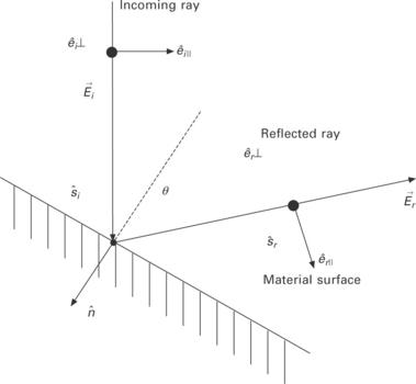
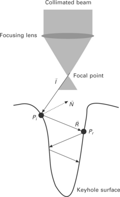
If light moves between media of differing refractive indices, both reflection and refraction (or absorption) of the light can be described by the Fresnel reflection model. The Fresnel reflection model determines the reflectivity of a material surface according to the polarization of the incidence beam. It has already been defined in previous reports and textbooks that the plane of incidence is a plane determined by two vectors of the incidence ray and surface normal. p-Polarization refers to the case where the polarization direction of the beam is parallel to the plane of incidence. On the other hand, s-polarization means that the polarization direction is perpendicular to the incidence plane. If a beam ray is irradiated vertically on the material surface, however, one cannot define whether it is s-polarization or p-polarization. Determination of the absorption rate of the material surface starts with dividing the electric field of the incoming beam ray, ![]() , into two components of the directional unit vector, as shown in Fig. 20.1 and as given in the following equations [18,19]:
, into two components of the directional unit vector, as shown in Fig. 20.1 and as given in the following equations [18,19]:
One of the directional components ![]() is parallel to the plane of incidence, which is determined by the incoming ray’s unit vector
is parallel to the plane of incidence, which is determined by the incoming ray’s unit vector ![]() and the negative surface normal
and the negative surface normal ![]() . This component represents the p-polarization case. The other, denoted as
. This component represents the p-polarization case. The other, denoted as ![]() , is perpendicular to the plane of incidence, and results in s-polarization. Each direction is decided by the polar angle of incidence θ, as delineated in Eq. [20.3]. The reflected ray vector
, is perpendicular to the plane of incidence, and results in s-polarization. Each direction is decided by the polar angle of incidence θ, as delineated in Eq. [20.3]. The reflected ray vector ![]() lying on the plane can be derived by the following simple equation, and the electric field of the reflected beam ray also should be split into two directions according to a
lying on the plane can be derived by the following simple equation, and the electric field of the reflected beam ray also should be split into two directions according to a ![]() nd
nd ![]() as described above:
as described above:
Er ⊥ and Er ⊥ are calculated by the Fresnel’s formula as follows:
where p and q are expressed as:
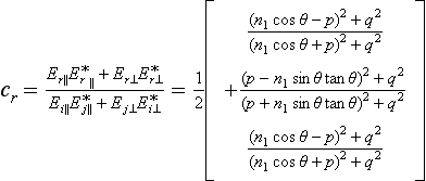
In the above equations, n1 is the refractive index of gas, n2 and k2 are the refractive and absorptive index of the material, respectively. The reflectivity cr and the absorption rate of the material surface ca are finally determined as follows:
where the asterisk superscript in the equation denotes a complex conjugate.
In Eq. [20.13], the reflectivity depends on the wavelength of the beam, the temperature of the surface, and the incident angle of the beam θ, because the complex refractive index of the material, m = n2 – ik2, varies with the wavelength of the beam and the temperature of the surface. The complex refractive index of the metal such as steel can be obtained by Drude theory. Because metal is generally a good conductor and free electrons move freely, the Lorentz model can have a special form: the Drude model with a vanishing spring constant leading to a resonance frequency of 0. Therefore, the complex refractive index can be obtained by solving the following equations:
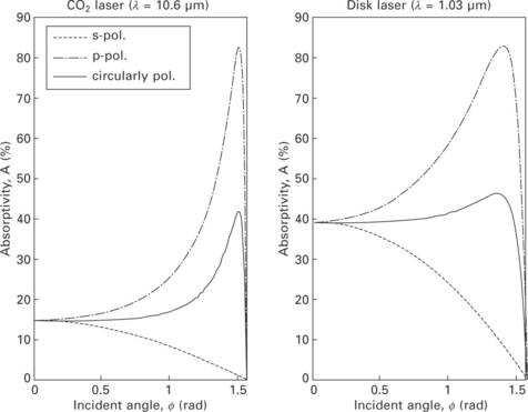
Here, ωp is the plasma frequency (rad/s), ω is the angular frequency of the laser (rad/s), τ is the relaxation time of electrons (s), N is the number of free electrons per cubic centimetre, e is the electron electric charge (C), m* is the optical mass of the electron (kg), ε0 is the permittivity of free space (F/m), σ0 is the conductivity of material (Ω/m) and γ is the damping frequency (Hz). Based on the Fresnel reflection model and Drude theory, Fig. 20.2 shows the absorptivity according to the incident angle between the incoming ray and the surface normal for a CO2 laser (10.6 mm) and a disk laser (1.03 μm).
The Fresnel reflection model of Eq. [20.13] can be simplified to Eq. [20.17] [20] by the Hagen-Rubens relation, ![]() (σdc is the dc-conductivity of the material), derived under the assumptions that the material is a good conductor and the wavelength of the beam is sufficiently long (infrared). In this equation, the reflectivity crs is a function of the incident angle of the beam and a laser- and material-dependent quantity, ε(ε2 ≈ 1/n22 ≈ 1/k22) [21,22]:
(σdc is the dc-conductivity of the material), derived under the assumptions that the material is a good conductor and the wavelength of the beam is sufficiently long (infrared). In this equation, the reflectivity crs is a function of the incident angle of the beam and a laser- and material-dependent quantity, ε(ε2 ≈ 1/n22 ≈ 1/k22) [21,22]:
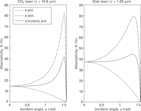
Here, ε1 and ε2 denote the real parts of the dielectric constants of metal and plasma, respectively, and ε0 denotes the permittivity of free space. Based on the simplified Fresnel reflection model and Hagen-Rubens relation, Fig. 20.3 shows the absorptivity according to the incident angle between the incoming ray and the surface normal for a CO2 laser (10.6 μm) and a disk laser (1.03 μm).
20.2.2 Laser heat source model
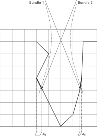
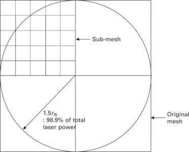
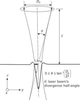
In terms of energy transfer, the laser beam undergoes rather complex processes. However, in the simplest case, the absorbed laser beam power at the keyhole wall might be described by considering only the Fresnel absorption, using a Gaussian-like surface heat flux [8]. Figure 20.4 shows one important problem when the surface heat flux is used without consideration of an axisymmetric laser beam in nature. If bundle 1 and bundle 2 are symmetric, for example, the energies of bundle 1 and bundle 2 should be the same. However, because the projected area of the free surface in cell 1, A1, is larger than the projected area of the free surface in cell 2, A2, the energy of bundle 1 is greater than that of bundle 2, a physically incorrect outcome. Therefore, it is necessary to define the bundles of rays whose energy distribution is Gaussian-like axisymmetric as well as whose number is finite but large enough to reproduce the real laser beam. To define the initial energies and directions of bundles of rays, the original mesh is divided at the focal plane into sub-meshes having smaller size, as schematically shown in Fig. 20.5. Then, the Gaussian-like energy distributions of the bundles at the focal plane can be predefined as given by:
Here, Asm is the area of a sub-mesh and ∆t is the time increment. After defining the initial energies of the bundles, the initial directions of the bundles can be defined according to the fact that bundles are limited by the optical geometry, which is related to the focal length f and the beam diameter on the optics Db, as shown in Fig. 20.6. That is, if the divergence half-angle of the laser beam is limited by Eq. [20.19] and all bundles pass through the focal point, the initial directions of the bundles can be generated.
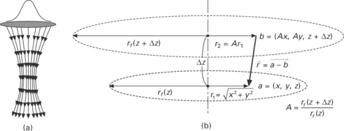
Besides the focal plane, any plane perpendicular to the axis of the laser beam can be used to define the initial energy values of the rays. The previous work assumed that the beam was focused on an infinitesimal point that defines the initial directions of the rays, but this step is practically impossible in laser welding. In the practical laser processing, however, the calculation of the focal spot size and the corresponding laser beam ray directions are based on the diffraction parameter. Because the disk laser used in welding is not diffraction-limited, the beam radius at position z along the axis of the beam can be expressed as follows:
Equation [20.20] implies that the beam is diffracted in the manner shown in Fig. 20.7(a), where the direction vector ![]() at any arbitrary point is calculated as shown in Fig. 20.7(b). In this calculation, the value of ∆z is given as the value of the original mesh size.
at any arbitrary point is calculated as shown in Fig. 20.7(b). In this calculation, the value of ∆z is given as the value of the original mesh size.
20.2.3 Multiple-reflection model of keyhole
The portion of total energy transfer from laser beam to flat material surface is quite small compared to other welding methods. However, it increases dramatically after a keyhole is generated because of the multiple reflection effect on the keyhole wall. Its basic concept is that a fixed portion of energy of the laser beam is absorbed at the irradiation point on the wall and the rest is reflected to the opposite wall and acts as a new energy beam. Most of the traveling rays in the keyhole are superposed at the keyhole bottom, which results in a deep penetration and an increase in the total energy absorption rate.
To implement the multiple reflections in analysis, a ray-tracing technique with the discrete grid cell system is proposed, as shown in Fig. 20.8. First of all, a ray vector is formed from the focal point to an arbitrary cell denoted as ![]() . Some portion of the energy contained in the ray is absorbed according to the Fresnel absorption model, which will be explained later, and the rest is delivered by the reflected ray
. Some portion of the energy contained in the ray is absorbed according to the Fresnel absorption model, which will be explained later, and the rest is delivered by the reflected ray ![]() to the point Pr on the opposite side by the following simple vector equation:
to the point Pr on the opposite side by the following simple vector equation:
where ![]() indicates the surface normal at the irradiated point Pi. In a discrete grid cell system, it is not possible to find an exact point consistent with a given
indicates the surface normal at the irradiated point Pi. In a discrete grid cell system, it is not possible to find an exact point consistent with a given ![]() vector. Therefore, it is necessary to make a temporary vector
vector. Therefore, it is necessary to make a temporary vector ![]() in Fig. 20.8 and select a point which makes the vector most similar to
in Fig. 20.8 and select a point which makes the vector most similar to ![]() . Its criterion is expressed in the following equation:
. Its criterion is expressed in the following equation:
In this equation, ![]() indicates the point to be irradiated by the reflected ray and
indicates the point to be irradiated by the reflected ray and ![]() the irradiated point by the incoming ray. ∆x is the distance between grids along the x axis and ∆y, ∆z are set to be equal to ∆x throughout the simulation. Proposed ray tracing is conducted for each ray incoming into the keyhole until there is no more point satisfying Eq. [20.22]. The whole of this process is expressed as a flowchart in Fig. 20.9. By using the suggested inverse tangent criterion, it is possible to trace the ray path even at the narrow bottom region in the keyhole as shown in Fig. 20.10 [13,14].
the irradiated point by the incoming ray. ∆x is the distance between grids along the x axis and ∆y, ∆z are set to be equal to ∆x throughout the simulation. Proposed ray tracing is conducted for each ray incoming into the keyhole until there is no more point satisfying Eq. [20.22]. The whole of this process is expressed as a flowchart in Fig. 20.9. By using the suggested inverse tangent criterion, it is possible to trace the ray path even at the narrow bottom region in the keyhole as shown in Fig. 20.10 [13,14].
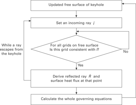
20.9 Flowchart of molten pool simulation process including multiple reflection iterations until a ray escapes from the keyhole.
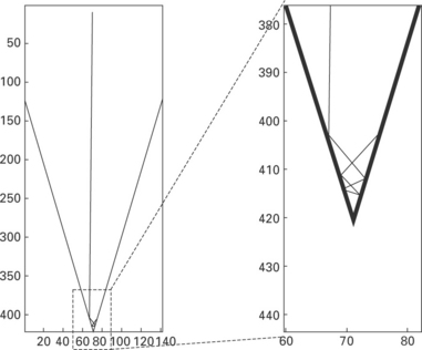
20.10 Example of ray-tracing technique proposed for an assumed keyhole. On the right is an enlarged picture of the keyhole bottom, which shows that the ray can reach to the bottom.
In addition, the aforementioned algorithms for searching the free surfaces and the multiple-reflection model are modified as follows [16,17]:
1. In the algorithm for searching the free surface cells, these are searched by comparing the fluid fraction F of 26 neighbouring cells with the critical fluid fraction Fcr. In the unmodified algorithm, however, many free surface cells are discarded at the narrow bottom region. In the modified algorithm, therefore, the searching algorithm for free surface cells at the narrow keyhole region is improved by increasing the critical fluid fraction Fcr, from 10− 6 to 0.5 and then by excluding the non-free surface cells indirectly by selecting the cell that has the shortest beam flight.
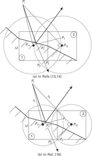
2. Figure 20.11 shows that the critical length, which is represented by the radius of the sphere, is decreased from ∆l to ![]() to improve the search accuracy; that is, the second cell vanishes and the first cell, which is more reliable, is selected automatically. For the case where multiple cells are candidates, the selected cell can be changed by the scan direction in the solution domain. Thus, a new procedure wherein a cell having the shorter length from the incident point is selected by comparing the length of each cell and is incorporated in the algorithm to guarantee the consistency of multiple reflections.
to improve the search accuracy; that is, the second cell vanishes and the first cell, which is more reliable, is selected automatically. For the case where multiple cells are candidates, the selected cell can be changed by the scan direction in the solution domain. Thus, a new procedure wherein a cell having the shorter length from the incident point is selected by comparing the length of each cell and is incorporated in the algorithm to guarantee the consistency of multiple reflections.
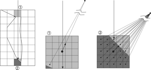
3. As shown in Fig. 20.12, the large original cell makes it impossible to accurately select a cell where the ray is incident. In this example, the ray is captured at cell ![]() and therefore unable to reach cell
and therefore unable to reach cell ![]() , which is wrong if the original cell is used in multiple reflections. Greater accuracy can be attained in the search for the cell on which the reflection occurs if the original cell is subdivided and if the sub-cells with fluid are selected on the basis of a comparison of the lengths between the sub-cell centre and a position which is sufficiently far (in the surface normal direction) from the centre of the original cell. The selected sub-cells can be used to test whether the ray is incident; cell
, which is wrong if the original cell is used in multiple reflections. Greater accuracy can be attained in the search for the cell on which the reflection occurs if the original cell is subdivided and if the sub-cells with fluid are selected on the basis of a comparison of the lengths between the sub-cell centre and a position which is sufficiently far (in the surface normal direction) from the centre of the original cell. The selected sub-cells can be used to test whether the ray is incident; cell ![]() can then be chosen for the next reflection cell in this example. As in other studies, the energy absorbed in a cell is redistributed by means of the weighting function to increase the computational efficiency.
can then be chosen for the next reflection cell in this example. As in other studies, the energy absorbed in a cell is redistributed by means of the weighting function to increase the computational efficiency.
20.2.4 Scattering model of keyhole
When an electromagnetic wave or a photon interacts with containing small particles, the radiative intensity may be changed by absorption and/or scattering. How much and in which direction a particle scatters an electromagnetic wave passing through its vicinity depends on (i) the shape of the particle, (ii) the material of the particle (i.e., the complex index of refraction, m = n–ik), (iii) its relative size, and (iv) the clearance between particles. In radiative analyses, the shape of particles is usually assumed to be spherical. These simplifying assumptions generally give excellent results.
In the following discussion, absorption and scattering by spherical particles, as shown in Fig. 20.13, are considered. An electromagnetic photon wave passing through the immediate vicinity of spherical particles will be absorbed or scattered. The scattering is due to three separate phenomena:
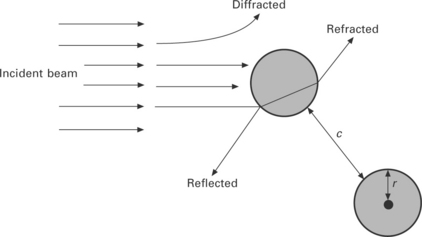
20.13 Interaction between electromagnetic waves and spherical particles [18].
• diffraction (waves never come into contact with the particle, but their direction of propagation is altered by the presence of the particle),
• reflection by a particle (wave reflected from the surface of the sphere), and
• refraction in a particle (waves that penetrate into the sphere and, after partial absorption, re-emerge traveling in a different direction).
The vast majority of photons are scattered elastically. A tiny fraction undergo inelastic Raman scattering. If scattering by one particle is not affected by the presence of surrounding particles, it is considered as independent scattering, otherwise it is dependent scattering. Thus, the radiative properties of a cloud of spherical particles of radius r, interacting with an electromagnetic wave of wavelength λ, are governed by three independent non-dimensional parameters: complex index of refraction, size parameter, and clearance-to-wavelength ratio. If scattering is independent (c/λ >> 1), then only the first two parameters are needed. The nature of the interaction between electromagnetic waves and particles is determined by the relative size of the particles compared with the wavelength of the radiation. Let us define a size parameter
where r is the effective radius of the particle. It is distinguished among three different regimes:
1. x << 1, Rayleigh scattering, named after Lord Rayleigh, who studied the interaction of atmospheric air (whose molecules are, in fact, very small particles) with sunlight [23]. He observed that, for very small particles, scattering is proportional to 1/λ4. Thus, within the visible part of the spectrum, blue light is scattered the most (accounting for blue skies) and red the least (resulting in red sunsets), as shown in Fig. 20.14.
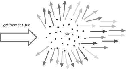
20.14 Scattering (why the sky is blue). Shorter-wavelength light is scattered out of the beam, leaving longer-wavelength light behind, so the sun appears yellow. In space, there’s no scattering, so the sun is white, and the sky is black (Georgia Tech. Prof. Rick Trebino’s lecture note).
2. x ~ 1, Mie scattering, named after Gustav Mie, who developed a comprehensive (and difficult) theory for the interaction between electromagnetic waves and particles [24].
3. x >> 1, normal surface, in this case the surface of the particle may be treated as a normal surface, and properties may be found through geometric optics. The high particle number density generated by laser causes the scattering of the incident light. And these particles lead to low degrees of transmission. Table 20.1 shows the classification of light-scattering phenomena.
Table 20.1
Classification of light-scattering phenomena
| 1. | Frequency shift/Energy transfer (1) Elastic scattering: Rayleigh, Mie scattering (negligible energy transfer) (2) Inelastic scattering: Brillouin, Raman, inelastic X-ray and Compton scattering |
| 2. | Particle size (1) Rayleigh scattering: Size parameter << 1 (2) Mie scattering: Size parameter ~ 1 |
| 3. | Density (1) Independent scattering: Disregard ‘interference’ (2) Dependent scattering: Consider ‘interference’ |
| 4. | Interference (1) Coherent scattering: Constructive with in-phase, Destructive with out-of-phase (2) Incoherent scattering: Waves adding with random phase, Partially cancelling |
20.2.5 Weld pool dynamics in laser welding
For analysis of the heat transfer and fluid flow in relation to the tracking free surface in the weld, solutions are found for the governing equations of mass conservation, momentum conservation (Navier–Stokes), energy conservation and the VOF. In the simulation, the molten metal is assumed to be an incompressible laminar flow with Newtonian viscosity.
With these assumptions, the governing equations can be expressed in Cartesian coordinates as follows:
where v is the velocity vector.
In Eq. [20.25], ρ is the fluid density, P is the pressure, v is the dynamic viscosity, K is the drag coefficient for a porous media model in the mushy zone, G is the body acceleration due to body force, C is a constant representing the mushy zone morphology, Fs is the solid fraction, B is the positive zero used to avoid the division by zero, v0 is the dynamic viscosity of the liquid phase and Fs,cr is a user-defined constant denoting the critical solid fraction value at which all fluid in the mushy zone freezes. It is assumed that the drag coefficient is zero and the dynamic viscosity is constant in the molten metal (over liquidus temperature), but in the mushy zone those are dependent on the solid fraction as shown in Eq. [20.25]. The third term on the right-hand side of Eq. [20.25] is the source term induced by the frictional dissipation in the mushy zone. The Carman-Kozeny equation derived from the Darcy model is used to model the flow in the mushy zone, with the assumption that this zone can be treated as a porous medium [25].
• Energy conservation equation:
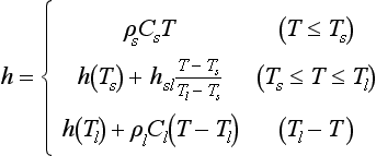
where h is the enthalpy, k is the thermal conductivity, and T is the temperature. The following enthalpy-based continuum model is used in many cases to consider the solid–liquid phase transition:
where h is the enthalpy, ρs and pl are the solid and liquid density, Cs and Cl are the specific heat at a constant volume of the solid and liquid phase, Ts and Tl are the solidus and liquidus temperature respectively, and hsl is the latent heat of fusion.
The keyhole formation process is a phenomenon of particular interest in laser welding. Its main driving force, called recoil pressure, involves the evaporation of material. The following model can be used in many cases to calculate the recoil pressure on the keyhole wall [26]:
where Psat is the saturated pressure, P0 is the atmospheric pressure, Lv is the latent heat of vaporization, Tb is the boiling temperature, and ![]() is the universal gas constant.
is the universal gas constant.
A surface tension model that Sahoo et al. [27] developed for a binary Fe-S system is used to model the Marangoni flow. Thus, the surface tension can be expressed as follows:
where γmo is the surface tension of pure metal at the melting point, A is the negative surface tension gradient for pure metal, Tm is the melting point, Γs is the surface excess at saturation, k1 is the constant related to the entropy of segregation, ai is the weight percent of sulphur, and ∆Ho is the standard heat of adsorption.
The buoyancy force (body force), which is modelled on the Boussinesq approximation, can be expressed as follows:
where g is the gravity, β is the thermal expansion rate, and T0 is the reference temperature.
For the simulation of bubble formation through a partial keyhole collapse, the transient distributions of the metal vapour and plasma or the shielding gas mixture in the keyhole should be determined by solving the governing equations of a multiphase problem. For the sake of simplicity, however, a bubble is assumed to be filled with an ideal gas and the heat transfer and mass transfer between the gas and molten metal are ignored. The bubble can be maintained by using the energy conservation equation and state equation; specifically, the pressure is increased as the volume is reduced [16,17].
In laser welding, metallic vapour is generated and ejected through the keyhole entrance. A spectroscopic measurement of a plume in 10 kW fibre laser welding confirms that the Inverse Bremsstrahlung effect is negligible; that the plume is weakly ionized; and that almost all the elements in the plume consist of neutral atoms of iron [28]. On account of the metallic vapour effect, the additional driving force and heat source are modelled on the assumptions that metallic vapour consists of iron vapour at a temperature of 6000 K [28] and that iron vapour is an ideal gas. The power absorbed during the welding process is calculated. The velocity of the metallic vapour at the keyhole entrance depends on the absorbed laser power density [29]. Inside the keyhole, the vapour velocity is assumed to increase linearly along the depth from zero velocity at the bottom of the keyhole to its calculated velocity at the entrance of the keyhole. The calculated velocity and average diameter of the keyhole suggest that the vapour flow is a laminar flow (Re < 2000); thus, the shear stress induced at the keyhole walls by the vapour can be expressed as follows [30]:
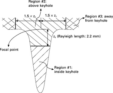
With regard to the heat source of the metallic vapour plume, the calculation region is divided as shown in Fig. 20.15. In region 1 (inside the keyhole), only the convective heat transfer is considered. The convective heat transfer coefficient can be expressed as follows, provided that the keyhole has a circular tube shape with a laminar flow of metallic vapour, and provided that there is a fully developed condition and a uniform surface heat flux [31]:
where D is the average diameter of the keyhole. In region 2 (above the keyhole), the convective heat transfer and the radiative heat transfer are both considered because the plume is observed to remain above the keyhole. Thus, an ambient temperature of 6,000 K is used to calculate the heat transfer in this region. This region is assumed to extend from the laser focal point to the bottom of the keyhole by a value of Rayleigh length. In region 3 (away from the keyhole), the convective heat transfer and the radiative heat transfer are calculated with respect to the ambient room temperature.
20.2.6 Laser–arc interaction
Laser arc hybrid welding, which simultaneously uses a high power laser and a conventional arc, has been developed to improve the welding speed and quality. After the development of hybrid welding techniques, a considerable number of studies have been carried out on system configurations, parameter optimization and the characteristics of weld beads. Although the hybrid welding plasma operates in a quite different way from the conventional one, little attention has been given to the new welding heat source. When the laser and arc plasma are used simultaneously, each heat source mutually assists and influences the other. The reason why the characteristics of hybrid plasma are improved is the generation of intensive metal vapour over the laser irradiated position. When the laser is irradiated on the metal surface, sufficient energy of light can cause metal vaporization and metal vapour can be further developed to laser induced plasma (LIP) plume by continuous supply of more laser energy. Because LIP is generated inside the arc plasma in laser arc hybrid welding, two kinds of plasma interact with and affect each other. In the coupling of laser and plasma, previous studies [32–34] have shown that the absorption of the laser beam is an important phenomenon; simulations have been used to understand this interaction effect. For the absorption mechanism of laser beams in the plasma, Inverse Bremsstrahlung, photoionization, and Mie absorption are considered in general [32,33]. In the case of Nd:YAG and CO2 lasers, Inverse Bremsstrahlung is dominant because of its relatively long wavelength [34], whereas it is known that for ultraviolet lasers the photoionization effect is dominant [33]. Additionally, the Mie absorption is dominant at low plasma temperature [35], when the effect of Inverse Bremsstrahlung and photoionization is low.
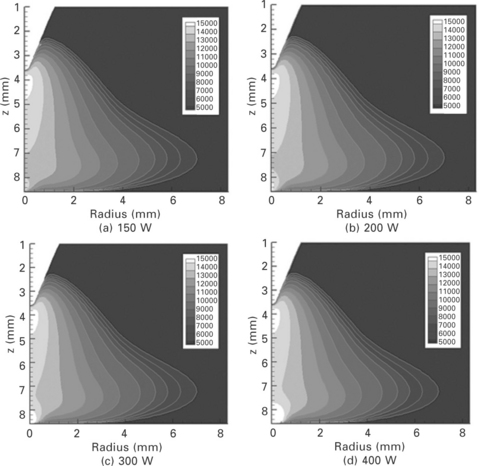
For CO2 laser-TIG hybrid welding, Startsev et al. [36] conducted a numerical simulation for a co-axial axisymmetric hybrid configuration. They considered the absorption of laser beams in the Ar arc plasma. The results show a significant temperature rise in the core of the arc, but LIP is not considered. LIP has been considered in laser welding simulation [33] but it has not yet been considered with arc plasma in hybrid welding. Cho et al. [37] focused on an investigation of the interaction mechanism between Nd:YAG laser and gas tungsten arc/LIP mixture plasma using numerical analysis. In addition to this, the characteristics of hybrid plasma such as temperature distribution, current density distribution and flow pattern are explained. In numerical simulations, the other absorption mechanisms, except for inverse Bremsstrahlung, are neglected for Nd:YAG LIP and Ar arc plasma. First, the temperature distribution of the base metal due to laser irradiation is obtained by solving the corresponding heat conduction equations. By fixing this result as the boundary condition, the distribution of metal vapour induced by the laser can be obtained. The distribution of temperature in the base metal and metal vapour are set as the boundary condition and analysis domain, respectively, in order to conduct the analysis of the hybrid plasma. The analysis is completed after checking the absorption of laser light in the plasma by Inverse Bremsstrahlung. The simulation results of temperature distributions for various laser powers are shown in Fig. 20.16. In the case of a laser with low power, the amount of evaporation is relatively small and the effect of current concentration decreases. Consequently, the local increase in plasma temperature gradually disappears. Conversely, the local increase in plasma temperature in the vicinity of laser irradiation is extended and the absolute value of temperature also increases when the laser power is high.
20.2.7 Modelling of arc welding process
The heat source of the electric arc can be modelled as a surface heat flux with a Gaussian function:
Here, ηA is the arc efficiency and V and I are the electric voltage and current of the arc, respectively. The pressure boundary condition of the arc plasma can be modelled by a Gaussian-like function [38]:
Here, μ0 denotes the magnetic permeability of free space.
Besides the gravitational force, the electromagnetic force that is generated by the electric current density and self-induced magnetic field is considered in the Navier–Stokes equation as body force. The analytical solutions for the vertical and radial components of the current density and the angular component of the magnetic field can be expressed as [39]:
Here, J0 is the first kind of Bessel function of zero order, c is the thickness of the workpiece, z is the vertical distance from the origin, J1 is the first kind of Bessel function of first order, and μm is the magnetic permeability of the material.
The plasma drag force is exerted on the surface due to impingement of the arc plasma jet flow and it causes an outward flow from the centre. To model the plasma drag force, the following analytical solution of the wall shear stress produced by the normal impingement of the jet on the flat surface was used [40]:
Here, τ is the shear stress, ρp is the plasma density, u0 is the initial plasma velocity, Re0 is the Reynolds number, H is the nozzle height, D is the nozzle diameter, r is the radius from the centre, and g2 is the universal function. In the calculation, it is assumed that H and D are the same as the arc length and electrode diameter, respectively. Finally, models of the surface tension and the buoyancy force are shown in Eqs [20.30] and [20.31].
As mentioned above, in addition to the models of GMA welding, the additional conservation equation is used for calculating the distributions of alloying elements:
Here, ![]() is the scalar source term added by an alloying element in molten drops. By Eq. [20.40], a scalar quantity indicating the weight percentage of the alloying element in a cell can not only be conserved but also is affected by the molten pool flow.
is the scalar source term added by an alloying element in molten drops. By Eq. [20.40], a scalar quantity indicating the weight percentage of the alloying element in a cell can not only be conserved but also is affected by the molten pool flow.
The arc power is about 6.5 kW (231 A, 28 V). For adding the droplet in the simulation, the droplet is moved at an angle of 61° to the horizontal with measured values of velocity and generation rate, and its temperature is assumed to be 2,400K. In addition, the droplet diameter can be calculated using the measured droplet generation rate and wire feed rate of 8 m/min. For calculating the alloying element distributions, chromium and nickel are addressed and their concentrations are all zero in the case of a SS400 workpiece, while they are 20% and 10% in the case of droplets of Y308 solid wire. Plates XXV and XXVI (between pages 328 and 329) show the temperature and Cr distributions with the flow patterns in GMA welding. At the weld start, where only a limited amount of base metal is melted and mixed with the filler metal, the Cr concentration is relatively high and decreases gradually as the welding progresses, before it reaches a stationary distribution condition after some time.
20.2.8 Weld pool dynamics in hybrid laser welding
In the numerical simulation of the hybrid welding process, three-dimensional transient simulations are conducted by combining the arc welding model and the laser welding model without any interactive effect between the two. The temperature profile characteristics of the weld bead and molten pool flow and alloying element distribution in the molten pool are analysed. It is found that fusion zones and alloying element distributions predicted by numerical simulations are quite similar to the experimental ones [16]. It shows that the assumptions and models used in this study are appropriate. Despite those fair prediction results, it is important to note that some other effects have not been taken into consideration in the proposed algorithm, including:
• the Inverse Bremsstrahlung representing the laser-arc plasma interactions;
• the Rayleigh scattering representing the laser-metal vapour interactions; and
• the heat and mass exchanges between the molten metal and the bubble.
Accordingly, it is deemed that further study that takes into account the overlooked effects noted above is necessary.
20.3 Applications for improving the laser welding technique and the quality of laser welded components
Three-dimensional simulation of molten pool dynamics in multi-kW laser welding is conducted. Basically, in a three-dimensional transient simulation of laser welding, the mass conservation equation, the momentum conservation equation, referred to here as the Navier–Stokes equation, the energy conservation equation and the VOF equation were used as governing equations to execute the molten metal flow analysis. Molten metal is assumed to be an incompressible laminar fluid with Newtonian viscosity. The simulation considers the buoyancy force, the Marangoni force, the recoil pressure, the vapour-induced shear stress, and the vapour-induced heat transfer, and the bubble pressure model is used to simulate the pore generation with a keyhole collapse.
Structural carbon steel (namely A36 (ASTM) or SS400 (JIS)) with a thickness of 12 mm is used in both the simulation and experiment. The disk laser power is 6 kW, and the travel speed is 1 m/min. Plates XXVII (a) to (c) (between pages 328 and 329) show the three-dimensional cross-sectional views of the simulation results. The red part is the molten region which has the temperature over the solidus temperature. At the beginning of the welding process, the upper part of the molten region is extended slightly in opposite, welding direction. The region is gradually extended over time, but ends up with almost the same length. With regard to the shape of the keyhole, it reaches its widest point at the opening, becomes narrow at the middle, and then becomes wider again at the end. Accordingly, the keyhole may collapse at the middle. In the simulation results, however, only a few pores came up, and this behaviour is acceptable in terms of the industrial standard (ISO 13919–1). The keyhole is considered to be relatively stable because the laser energy is distributed evenly by multiple reflections rather than being focused at a specific region.
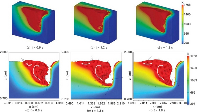
Plate XXVII (a)-(c) Calculated temperature profiles and flow patterns in a three-dimensional cross-sectional view; (d)-(f) cross-sectional side view during laser welding.
Plates XXVII (d) to (f) show the calculated temperature profiles and flow patterns from a cross-sectional side view. Clearly, as mentioned above, the molten pool is stretched at the upper part. Except for the upper part, however, the shape of the molten pool remains almost unchanged over time, probably due to the fact that the same flow pattern, namely a clockwise vortex, is maintained in the molten pool. This flow pattern helps transport the molten metal heated by the laser to the rear upper part of the molten pool. Because of this phenomenon, the rear upper part is extended over time in the opposite welding direction. The molten pool flow in this part oscillates back and forth, so that no specific flow pattern can be defined. The bottom of the keyhole is cooled relatively quickly because the strong flow pushes the molten metal in this region, which is bound by a large solid region. A narrow molten pool is consequently generated and acceptably small pores appear in this region.
Plate XXVIII (between pages 328 and 329) shows the temperature profiles and fluid flows from a cross-sectional front view. After a dimpled shape appears near the surface, as shown in Plate XXVIII(a), a keyhole is generated and a small amount of molten metal exists around the keyhole. As shown in Plate XXVIII(b), a downward flow was observed for about 0.1 s in a small region behind the keyhole, most likely due to the recoil pressure. At t = 1.0 s, the downward flow disappears and an upward flow appears. The upward flow is dominant for a long time until the solidification is completed. The solidification starts at the bottom and, as a result, the last solidification occurs in the upper molten region.
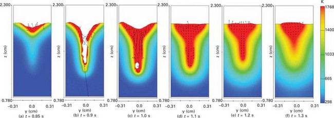
Plate XXVIII Calculated temperature profiles and flow patterns in a cross-sectional front view during laser welding.
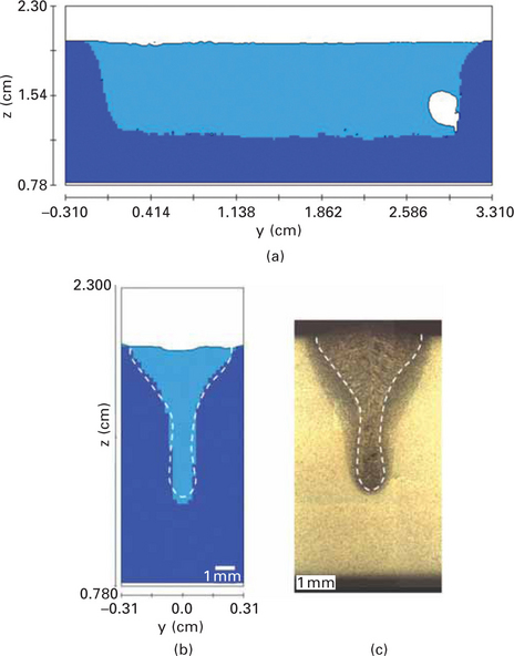
Plate XXIX (between pages 328 and 329) compares the simulation results of the weld bead cross section with the experimental results to verify the welding models and algorithms used in simulations. Plate XXIX(a) and (b) shows the simulation results of the fusion zones in the transverse and longitudinal cross sections after the solidification of the molten pool. In the experiment, the weld bead was polished and etched to show the fusion zone, and a transverse cross section is shown in Plate XXIX(c). The profile of the calculated fusion zone Plate XXIX(b) is in considerably good agreement with the experimental results Plate XXIX(c).
As mentioned above, in addition to the models of the GMAW and laser welding, the additional conservation equation is used for calculating the distributions of alloying elements. The separation between the arc and laser is 3 mm with the GMA leading the laser, and the laser and arc power is 6 kW and about 6.5 kW (231 A, 28 V), respectively. For adding the droplet in the simulation, the droplet is assumed to move at an angle of 61° to the horizontal plane with measured values of velocity and generation rate. Its temperature is assumed to be 2,400 K. In addition, the droplet diameter can be calculated using the measured droplet generation rate and wire feed rate of 8 m/min. For calculating the alloying element distributions, chromium and nickel are addressed and their concentrations are all zero in the case of a SS400 workpiece, while they are 20% and 10% in the case of droplets of Y308 solid wire. The case of 1.8 s laser-GMA hybrid welding and a 1.2 s cooling process is simulated and analysed.
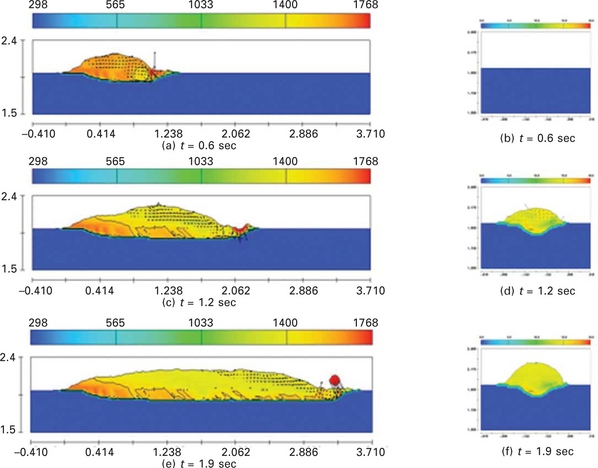
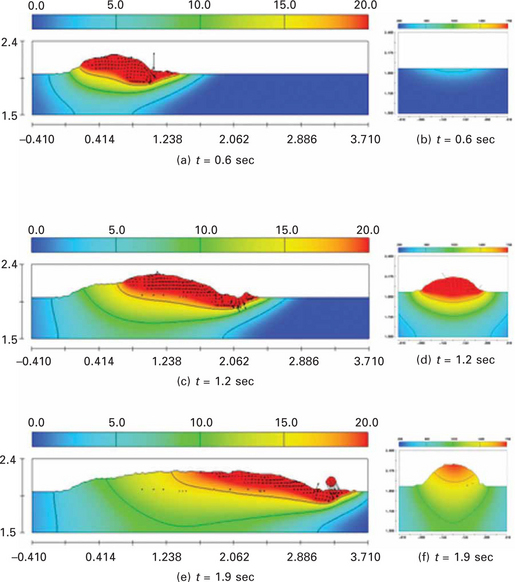
Plate XXX (between pages 328 and 329) shows the temperature and Cr distributions with the flow patterns in the longitudinal cross sections during hybrid welding. In the figures, maximum temperature and concentration values of Cr are set to 1,768 K and 8%, respectively. First, the molten pool with the flow patterns is analysed. At the keyhole front, where a high intensity laser beam is directly irradiated, the material is removed without a thin molten layer, a process that resembles the laser cutting and drilling process. The laser beam reflected at the keyhole front reaches the other position of the keyhole wall and is then absorbed. As shown in the figures, not only can the incident beam reach the keyhole wall easily, but also the reflected beam can be collected around a specific point, if the shape of the keyhole is not smooth but rather has a bulge. In particular, the region is rapidly expanded by the excessive recoil pressure, if the reflected laser beam is concentrated at the rear part of the keyhole surrounded by the molten metal. For this reason, complex flows with relatively high velocity are observed near the keyhole and can make the keyhole unstable. Meanwhile, it is observed that clockwise-rotating vortices form a quasi-steady state flow pattern in the wide molten region located away from the keyhole. It can be inferred that these vortices are driven by the strong flow at the keyhole. Because the vortices extending a relatively wide range of the molten pool not only have high Cr content but also rotate in the same direction, they help mix Cr in the molten pool and thus Cr is distributed uniformly in the wide molten region. However, the outer clockwise-rotating vortex with relatively high or low Cr content passes through around the solid–liquid interface, and thus Cr can be entrapped and make a pattern like the teeth of a comb. In this simulation, this type of alloying element distribution pattern can be observed but is not severe, when compared to the results of full penetration hybrid welding experiments, although the experiments were carried out with different welding parameters and filler metal [41]. For the region around the keyhole bottom, strong up- and-back flow arises and pushes out the flow having high content of alloying elements because of the fast cooling rate and small accompanying molten region. Therefore, low content of alloying elements exists in the keyhole bottom.
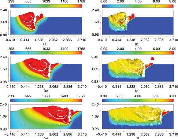
Plate XXX Simulation results in longitudinal cross sections during hybrid welding, (a) temperature profile at t = 0.6 sec, (b) Cr profile at t = 0.6 sec, (c) temperature profile at t = 1.2 sec, (d) Cr profile at t = 1.2 sec, (e) temperature profile at t = 1.8 sec and (f) Cr profile at t = 1.8 sec.
Plate XXXI (between pages 328 and 329) shows the simulation results of fusion zone and Cr and Ni distributions in the transverse and longitudinal cross sections after solidification of the molten pool. In these figures, maximum content values of Cr and Ni are set to 8 and 4%, respectively, for clear comparison with experiments. In the experiment, the weld was polished and etched to analyse the fusion zone. An electron prove micro analyzer (EPMA) was used to investigate the alloying elements of Cr and Ni in the weld, and the experimental results are shown in Plate XXXII (between pages 328 and 329). For the calculated fusion zone in Plate XXXI(a), the penetration depth and melting width are predicted considerably accurately, while the fusion zone is a little wider at the middle region in comparison with the experimental result of Plate XXXII(a). Given the observation of a fluctuating fusion zone in both Plate XXXI(b) and Plate XXXII (b), it appears that the laser induced keyhole is rather unstable, which can be explained by the unstable nature of the keyhole. From the simulation results for alloying element distributions presented in Plates XXXI (c) to (f), it is seen that the lower part of the molten region is very narrow and has a relatively low content of alloying elements. On the other hand, the upper part of the molten region is considerably wide and has a relatively high content of alloying elements. Between these two parts, a transitional region, where high and low contents of alloying elements coexist, is observed and wave-shaped patterns are extended from the bottom to the up-and-opposite direction of welding. Plate XXXI shows that strong up-and-back flow with low Cr content and outer clockwise-rotating vortex with high Cr content is intersected in this region. However, the pattern like the teeth of a comb is not remarkable because the alloying element is distributed relatively uniformly, when compared to the results of full penetration experiments [41]. These simulation results are in fairly good agreement with the experimental results in Plates XXXII(c)–(f). Shown as dashed lines in Plates XXXII(a), (c), and (e), the boundaries of the fusion zone and alloying elements are quite similar, indicating that the alloying elements can be reached only at the molten region under these welding conditions. Although the absolute content of Cr is twice that of Ni in the solid wire, the distribution characteristics of Cr in Plates XXXII(c) and (d) are quite similar with those of Ni in Plates XXXII (e) and (f). From the aforementioned results, it is thought that the distributions of the alloying element such as Cr and Ni are affected mainly by the molten metal flow and also that their diffusive effects are negligible in this case. By the simulation where the diffusive effect of each alloying element is not considered, identical patterns of Cr and Ni are calculated as shown in Plates XXXI(c)–(f).
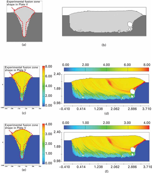
Plate XXXI Simulation results in transverse and longitudinal cross sections after solidification: (a) transverse cross section (fusion zone), (b) longitudinal cross section (fusion zone), (c) transverse cross section (Cr), (d) longitudinal cross section (Cr), (e) transverse cross section (Ni) and (f) longitudinal cross section (Ni).
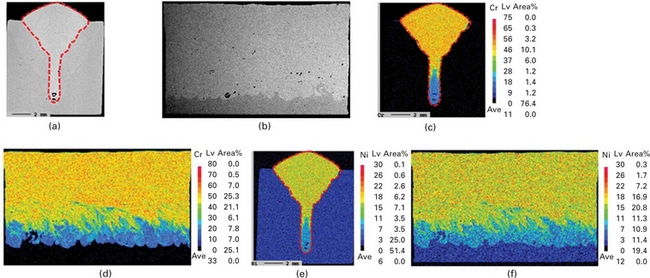
Plate XXXII Experimental results in transverse and longitudinal cross sections: (a) transverse cross section (etched), (b) longitudinal cross section (etched), (c) transverse cross section (Cr), (d) longitudinal cross section (Cr), (e) transverse cross section (Ni) and (f) longitudinal cross section (Ni).
20.4 Future trends
Using the aforementioned models for laser and arc welding, reasonable predictions can be made based on the comparison of fusion zone shape and alloying element distribution between the numerical calculation and the experimental observation. However, it should be pointed out that the developed models are far from the full solutions to the welding process, and developing a united model for the welding is very challenging. In particular, in the hybrid process the new phenomena such as the synergistic interaction of the laser and electric arc and the effect of the coupled parameters should be considered. The origins of those phenomena are not well understood and many important questions related to such modelling are still unanswered, which bring more difficulties for modelling of the hybrid welding. The main challenges for such modelling are as follows [42].
First, the synergistic interaction of the laser and electric arc is not well understood in terms of the following phenomena: the electric arc preheats the base metal that enhances the absorption of the laser energy by the target metal; the electric arc dilutes the laser induced plasma and hence reduces the ability of the plasma to absorb and reflect the laser energy; the laser beam stabilizes the electric arc; the laser induced metal vapour and plasma distort the electric arc structure; and the synergistic interaction of laser–arc changes the energy transfer and hence the welding process.
Second, the laser beam and the laser induced metal vapour significantly influence the features of metal transfer, but the underlying physics is still unclear. The transient arc plasma and droplet generation were ignored, and/or the droplets were assumed to impinge into the weld pool at a fixed size and frequency in the existing models, which fail to couple the generation of arc plasma, droplet formation, detachment and transfer during hybrid welding.
Third, the effects of shielding gas, including its composition, flow rate and injecting direction, are still unclear. The shielding gas has significant influence on the plasma formation, the arc stability and hence the weld quality in hybrid welding, which depends on the intrinsic properties of the shielding gas. However, the effects of the shielding gas in hybrid welding are contradictory in some functions for the individual welding process, which requires further research to reduce the plasma shielding effect for the laser and also enhance the electric arc stability.
Finally, a real united model of hybrid laser–GMA welding will need an excess computation time. Therefore, more advanced computer technology and a more time-efficient computation method are required.
20.5 References
[1] Schmidt, M., Otto, A., Geiger, M. Analysis of YAG laser lap-welding of zinc coated steel sheets. CIRP Ann – Manuf. Technol.. 2008; 57:213–216.
[2] Sathiya, P., Abdul Jaleel, M. Y., Katherasan, D. Optimization of welding parameters for laser bead-on-plate welding using Taguchi method. Prod. Eng. Res. Devel.. 2010; 4:465–476.
[3] Seto, N., Katayama, S., Matsunawa, A. High-speed simultaneous observation of plasma and keyhole behavior during high power CO2 laser welding: effect of shielding gas on porosity formation. J. Laser Appl.. 2000; 12:245–250.
[4] Rosenthal, D. Mathematical theory of heat distribution during welding and cutting. Weld. J.. 1941; 20:220s–234s.
[5] Zacharia, T., David, S. A., Vitek, J. M., Debroy, T. Weld pool development during GTA and laser beam welding of type 304 stainless steel, part I – theoretical analysis. Weld. J.. 1989; 68:499s–509s.
[6] Huan, J., Nie, P., Deng, D., Li, Z. Finite element analysis of laser fillet welding T-joint of thin mild steel plates. In: Vollertsen F., ed. Proceedings of the IWOTE’11: International Workshop on Thermal Forming and Welding Distortion. Germany: Bremen; 2011:255–261.
[7] van der Aa, E. M., Hermans, M. J. M., Richardson, I. M. Simplified models for the investigation of longitudinal welding stress and strain development. In: Vollertsen F., Sakkiettibutra J., eds. Proceedings of the IWOTE’08: International Workshop on Thermal Forming and Welding Distortion. Germany: Bremen; 2008:171–180.
[8] Kaplan, A. A model of deep penetration laser welding based on calculation of the keyhole profile. J. Phys. D-Appl. Phys.. 1994; 27:1805–1814.
[9] Ki, H., Mohanty, P. S., Mazumder, J. Modelling of high-density laser-material interaction using fast level set method. J. Phys. D-Appl. Phys.. 2001; 34:364–372.
[10] Osher, S., Sethian, J. A. Fronts propagating with curvature-dependent speed: algorithms based on Hamilton-Jacobi formulations. J. Comput. Phys.. 1988; 79:12–49.
[11] Lee, J. Y., Ko, S. H., Farson, D. F., Yoo, C. D. Mechanism of keyhole formation and stability in stationary laser welding. J. Phys. D-Appl. Phys.. 2002; 35:1570–1576.
[12] Hirt, C. W., Nichols, B. D. Volume of fluid method for the dynamics of free boundaries. J. Comput. Phys.. 1981; 39:201–225.
[13] Cho, J. H., Na, S. J. Implementation of real-time multiple reflection and Fresnel absorption of laser beam in keyhole. J. Phys. D-Appl. Phys.. 2006; 39:5372–5378.
[14] Cho, J. H., Na, S. J. Theoretical analysis of keyhole dynamics in laser drilling considering the polarization of laser. J. Phys. D-Appl. Phys.. 2007; 40:7638–7647.
[15] Cho, J. H., Na, S. J. Three-dimensional analysis of molten pool in GMA-laser hybrid welding. Weld. J.. 2009; 88:35s–43s.
[16] Cho, W. I., Na, S. J., Cho, M. H., Lee, J. S. Numerical study of alloying element distribution in CO2 laser-GMA hybrid welding. Comput. Mater. Sci.. 2010; 49:792–800.
[17] Cho, W. I., Na, S. J., Thomy, C., Vollertsen, F. Numerical simulation of molten pool dynamics in high power disk laser welding. J. Mater. Process. Technol.. 2012; 212:262–275.
[18] 18. Bang, S. Y., 1991. Effects of multiple reflections and beam polarization on laser grooving of hard ceramics. PhD thesis, Pennsylvania State University.
[19] Modest, M. F. Radiative Heat Transfer. New York: Mc-Graw-Hill; 1992.
[20] Stratton, J. A. Electromagnetic Theory. New York: McGraw-Hill; 1941.
[21] Schulz, W., Simon, G., Urbassek, H. M., Decker, I. On laser fusion cutting of metals. J. Phys. D: Appl. Phys.. 1987; 20:481–488.
[22] Ducharme, R., Williams, K., Kapadia, P., Dowden, J., Steen, B., Glowacki, M. The laser welding of thin metal sheets: an integrated keyhole and weld pool model with supporting experiments. J. Phys. D: Appl. Phys.. 1994; 27:1619–1627.
[23] Rayleigh, L. On the electromagnetic theory of light. Phil. Mag.. 1881; 12:81–101.
[24] Mie, G. A. Beiträge zur Optik trüber Medien. speziell kolloidaler Metallösungen. Annalen der Physik. 1908; 25:377–445.
[25] Voller, V. R., Prakash, C. A fixed grid numerical modelling methodology for convection-diffusion mushy region phase-change problems. Int. J. Heat Mass Transf.. 1987; 30:1709–1719.
[26] Allmen, M., Blatter, A. Laser-Beam Interactions with Materials, 2nd ed. New York: Springer; 1995.
[27] Sahoo, P., Debroy, T., McNallan, M. J. Surface tension of binary metal-surface active solute systems under conditions relevant to welding metallurgy. Metall. Mater. Trans. B-Proc. Metall. Mater. Proc. Sci.. 1988; 19:483–491.
[28] Katayama, S., Kawahito, Y., Mizutani, M. Elucidation of laser welding phenomena and factors affecting weld penetration and welding defects. Physics Procedia. 2010; 5:9–17.
[29] Amara, E. H., Bendib, A. Modelling of vapor flow in deep penetration laser welding. J. Phys. D-Appl. Phys.. 2002; 35:272–280.
[30] White, F. M. Fluid Mechanics, 4th ed. New York: McGraw-Hill; 1999.
[31] Incropera, F. P., Dewitt, D. P. Introduction to Heat Transfer, 3rd ed. New York: John Wiley & Sons; 1996.
[32] Schittenhelm, H., Callies, G., Straub, A., Berger, P., Hugel, H. Measurements of wavelength-dependent transmission in excimer laser-induced plasma plumes and their interpretation. J. Phys. D: Appl. Phys.. 1998; 31:418–427.
[33] Rozman, R., Grabec, I., Govekar, E. Influence of absorption mechanisms on laser-induced plasma plume. Appl. Surf. Sci.. 2008; 254:3295–3305.
[34] Yilbas, B. S., Yilbas, Z., Akcakoyun, N. Investigation into absorption of the incident laser beam during Nd:YAG laser processing of metals. Opt. Laser Technol.. 1996; 28:503–511.
[35] Callies, G., Schittenhelm, H., Berger, P., Hugel, H. Modeling of the expansion of laser-evaporated matter in argon, helium and nitrogen and the condensation of clusters. Appl. Surf. Sci.. 1998; 127–129:134–141.
[36] Startsev, V. N., Martynenko, D. P., Leonov, A. F. Investigation of characteristics of an arc column in laser arc welding using numerical simulation. High Temp.. 2000; 38:20–25.
[37] Cho, Y. T., Cho, W. I., Na, S. J. Numerical analysis of hybrid plasma generated by Nd:YAG laser and gas tungsten arc. Opt. Laser Technol.. 2011; 43:711–720.
[38] Cao, Z., Yang, Z., Chen, X. L. Three-dimensional simulation of transient GMA weld pool with free surface. Weld. J.. 2004; 83(6):169s–176s.
[39] Kou, S., Sun, D. K. Fluid flow and weld penetration in stationary arc welds. Metall. Trans. A. 1985; 16(A):203–213.
[40] Phares, D. J., Smedley, G. T., Flagan, R. C. The wall shear stress produced by the normal impingement of a jet on a flat surface. J. Fluid Mech.. 2000; 418:351–375.
[41] Zhao, L., Sugino, T., Arakane, G., Tsukamoto, S. Influence of welding parameters on distribution of wire feeding elements in CO2 laser GMA hybrid welding. Sci. Technol. Weld. Join.. 2009; 14(5):457–467.
[42] Rao, Z. H., Liao, S. M., Tsai, H. L. Modelling of hybrid laser-GMA welding: review and challenges. Sci. Technol. Weld. Join.. 2011; 16(4):300–305.

