Developments in twin-beam laser welding technology
Abstract:
In this chapter the phenomenon, mechanism and method of twin-beam laser irradiation are introduced. Welding, including dissimilar materials welding, surface modification and cutting of a brittle material, are shown as particular applications of twin-beam laser welding. The advantages and effects of the technique are described. An analytical study on the convection behavior occurring during twin-beam laser irradiation is also shown as an example of using a numerical approach to understand the mechanism of twin-beam laser welding.
16.1 Introduction
There are many advantages to laser welding, such as its small heat-affected zone, deep penetration, precision welding, high applicability for robotics technology, etc. There are, however, some limitations to the optimization of single-beam welding parameters for improving weldability, and weld quality, such as laser power, pulse condition and spot size, because they strongly depend on the kind of laser beam used. Twin-beam or dual-beam laser irradiation has been developed to overcome the limitations of single-beam irradiation welding. Twin-beam or dual-beam laser irradiation means that two laser beams are used at the same time in one process. Two effects are expected from the use of twin-beam irradiation: an increase in the number of heat sources compared to single-beam irradiation and the ability to realize different phenomena. The main result of applying a twin beam instead of a single one may simply be an increase in the power of the laser. The power of twin-beam irradiation is not, however, the simple sum of two beams. Sakamoto et al. [1] studied energy coupling in twin-beam laser irradiation. According to their calculation of the energy coupling rate based on the Gouffe-Dausinger model, the keyhole opening size, which is not simply the sum of the diameters of the two laser spots, was assumed to be a spot diameter when the distance between two beams was narrow. Furthermore, it is also expected that two heat sources can produce different temperature distributions and histories during the process, even if two of the same type of laser beam are used. In cases where two different types of laser beams are applied, complex and interesting phenomena can also be expected. This chapter introduces twin-beam laser welding techniques and describes methods of twin-beam laser irradiation and its phenomena and mechanism. Examples of the applications of twin-beam laser irradiation are also described to demonstrate its advantages.
16.2 Numerical study on molten metal flow behavior during twin-beam irradiation
The use of two heat sources as opposed to one, i.e. applying a twin beam instead of a single beam, has a significant effect on the flow behavior of molten metal. In this section, a comparison of the convection behavior in the molten pool during both single- and twin-beam laser irradiation is provided [2]. A magnesium alloy was the metal alloy used in the analysis, the physical properties of which are shown in Table 16.1.
Table 16.1
Thermo-physical properties of the material used for the analysis
| Heat conductivity, kW m- 1 K- 1 | 155 |
| Specific heat capacity, J kg- 1 K- 1 | 1360 |
| Liquid metal density, kg m- 3 | 1738 |
| Expansion coefficient of volume, K- 1 | 1.523 × 10- 4 |
| Surface tension gradient, kg s- 2 K- 1 | − 1.49 × 10- 4 |
| Liquid metal viscosity, m2 s- 1 | 1.23 × 10- 3 |
| Melting temperature, °C | 650 |
| Ambient temperature, °C | 25 |
| Coefficient of heat emission, Wm- 2 K- 1 | 125 |
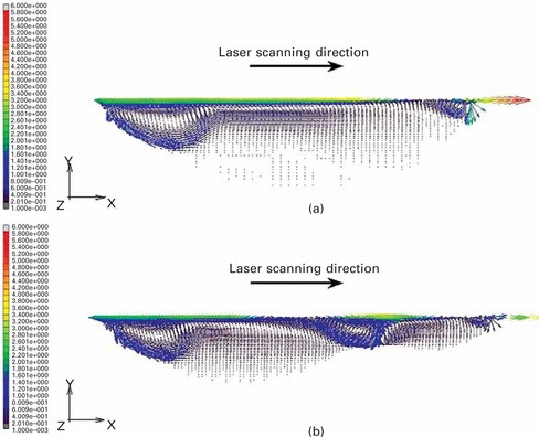
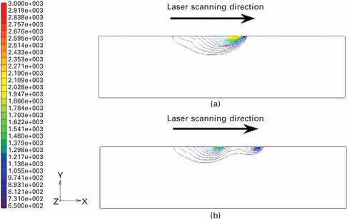
Plate XIV (between pages 328 and 328) shows molten pool shapes in the cross section perpendicular to the laser scanning line, which were created using both single- and parallel twin-beam irradiation. For the purposes of the analysis, the region with a temperature above the melting temperature of a magnesium alloy was assumed to be the molten pool region. The total applied energy was the same for both the single and the twin-beam in this case, meaning that during the twin-beam irradiation, each beam used about half of its total applied energy. The maximum temperature at the laser irradiated point in the twin beam was, therefore, lower than that in the single beam. Plate XV (a) (between pages 328 and 329) shows the convection behavior in the cross section perpendicular to the laser scanning line in the case of single-beam irradiation. This was calculated according to the temperature distribution as shown in Plate XIV. Plate XV (a) shows the flow direction travelling from the inside to the outside around the laser irradiation point. The middle of the molten pool shows almost no flow. Flow behavior following irradiation using parallel twin beams is shown in Plate XV (b). In this case, surface tension from the irradiation point of each beam directs the flow to the center between the two beams, and flow from the top to the bottom occurs at the center of the molten pool.
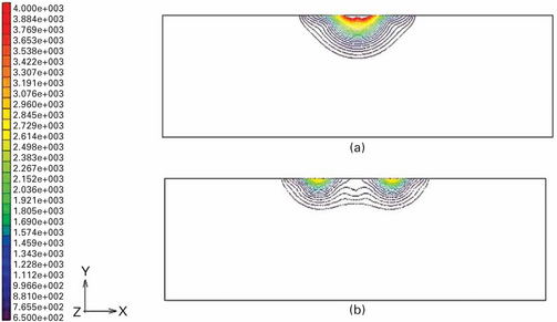
Plate XIV Weld pool shape in the cross section perpendicular to the laser scanning direction obtained by FEM analysis: (a) single-beam irradiation, (b) parallel twin-beam irradiation.
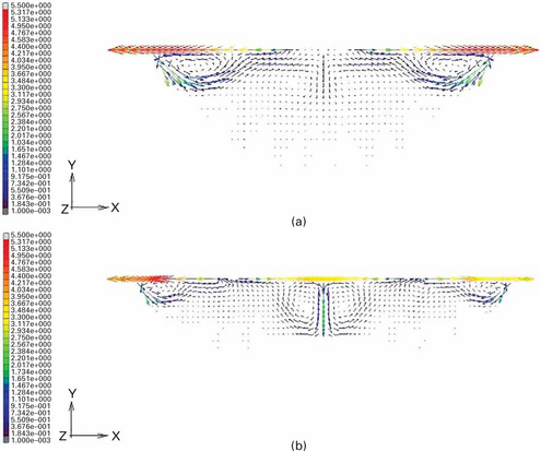
Plate XV Flow pattern in the cross section perpendicular to the laser scanning direction obtained by FEM analysis: (a) single-beam irradiation, (b) parallel twin-beam irradiation.
Plate XIV (between pages 328 and 329) shows molten pool shapes obtained in the cross section parallel to laser scanning line following both single- and tandem twin-beam irradiation. It is clear from the figure that the molten pool shapes created by the two types of irradiation are completely different. Plate XVII (between pages 328 and 329) shows flow behavior in the cross section parallel to laser scanning line by both single- and tandem twin-beam irradiation. In the case of single-beam irradiation, convection is not significantly observed in the middle part of the molten pool. In the case of the tandem twin-beam irradiation, however, flows are significantly observed at the end and middle sections of the molten pool. The two different convection flows induced by two-beam irradiation affect one another and cause the flows to become active in the middle section of the molten pool. Additionally, the total duration for melting of the material is longer in the tandem beam irradiation.
16.3 Apparatus and procedure of twin-beam laser technique
There are two methods of creating a twin-beam laser for welding: splitting one laser beam into two beams using a prism or a mirror, or using two laser oscillators. The former method has the advantages of a simple structure and low cost, whilst the latter allows the operator to control the two beams separately and precisely to create the phenomena caused by mixing different beams.
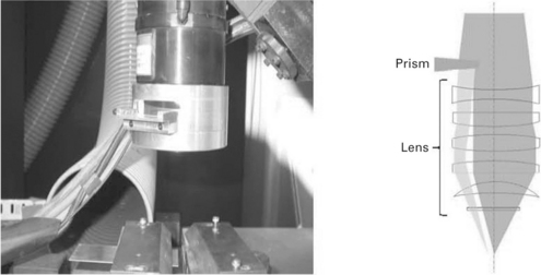
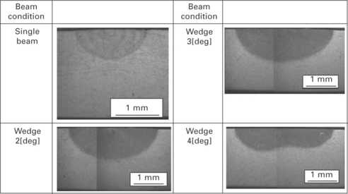
Figure 16.1 shows an example of a twin beam apparatus. When prisms are used to split a laser beam, the beam distance and intensity ratio can be controlled by altering the wedge angle and insert distance of the prism used [3]. Figure 16.2 shows a cross section of an aluminum alloy sheet following twin-beam laser irradiation. The distance between the two beams is changed by altering the wedge angle of the prism.
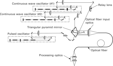
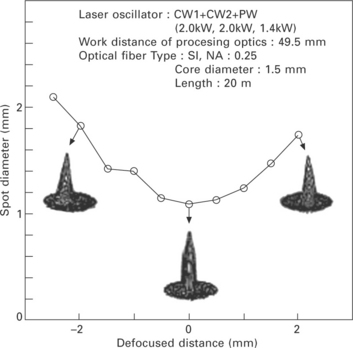
When two oscillators are used, two or more beams can be applied either in the same optical line or a different line. Figure 16.3 shows a three oscillator laser welding system [4]. Energy distribution obtained by applying three oscillators is shown in Fig. 16.4. In this case, two CWs and one pulse laser beam are applied through one single optical line. Figure 16.4 shows that three beams are not separated from one another and it seems like a one-beam irradiation. The actual waveform is almost following the command waveform as shown in Fig. 16.5.
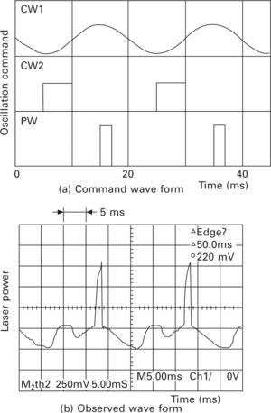
16.5 Laser power profile using the three-beam laser welding system: (a) command wave form, (b) observed wave form.
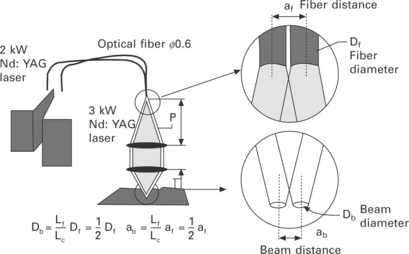
Figures 16.6 and 16.7 show schematics of a twin-beam laser welding system and the distribution of beam intensity observed by using the system [5]. In this case, the beam distance is controlled by the distance between the optic fibers.
16.4 Application of twin-laser beam
16.4.1 Welding
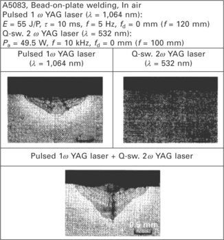
Jonghyan et al. [6] reported the melting characteristics of various metals following irradiation by combined lasers with different wavelengths. A Q-switched YAG laser and pulsed YAG laser were combined both through different optics lines and the same optics line as shown in Figs 16.8 (a) and (b), respectively. Figure 16.9 shows cross sections of a weld bead obtained both by single-beam irradiation and twin-beam irradiation. In this example, the Q-switch and pulse YAG laser were applied through different optical lines. The size and depth of the molten pool were increased after twin-beam irradiation. Figure 16.10 shows a cross section of weld bead obtained using twin-beam irradiation in different metals. Keyhole type penetration was observed and the molten area and depth of the molten pool increased following twin-beam laser irradiation (Fig. 16.10). The effect of twin-beam laser irradiation is schematically shown in Fig. 16.11. In cases where a highly reflective and thermally conductive material was used, two layers of molten pool were observed. Contrastingly, in cases where materials with a low thermal conductivity were used, deeper penetration was obtained. Jonghyan et al. [6] reported that the absorptivity of the laser increased when twin-beam laser irradiation was used by 21%, 29% and 25% for a pure copper, A5083 and SUS304, respectively.
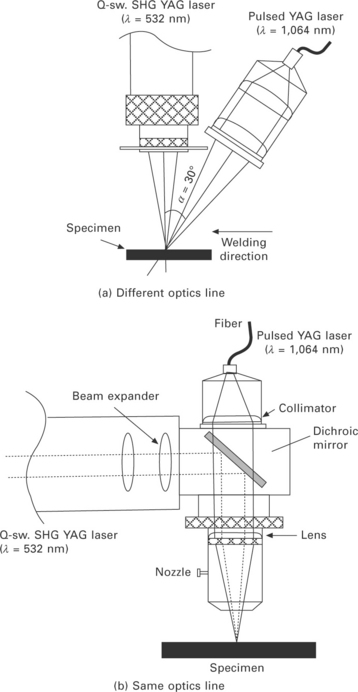
16.8 Combination between Q-switched YAG laser and a pulsed YAG laser: (a) different optics line, (b) same optics line.
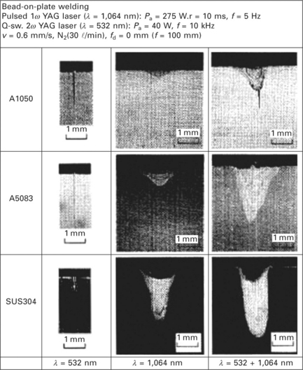
16.10 Cross sections of weld bead obtained by single-beam irradiation and twin-beam irradiation in different metallic materials.
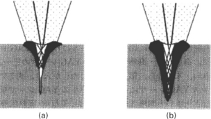
16.11 Effect of twin-beam laser irradiation in (a) high reflective and high thermal conductive material, (b) low thermal conductive material.
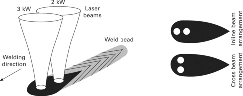
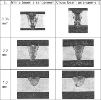
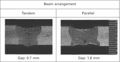
Shibata et al. [7] studied the effect of twin spot beam configuration on the overlap joint welding of aluminum alloys. Two different Nd:YAG laser beams were separately applied as shown in Fig. 16.6. During this study the distance between the two beams was changed. Figure 16.7 shows the beam profile obtained at different beam distances. Tandem beam and parallel beam configurations were applied as shown in Fig. 16.12. Figure 16.13 shows a cross section of a weld bead. The penetration depth decreased with the increase in beam distance for both beam configurations. When the beam distance became too short, however, the welding process became unstable. The configuration of twin beams should be selected depending on material thickness, laser power and scanning speed in order to obtain higher quality welding.
The effect of the twin-beam laser irradiation on porosity formation was studied by Shibata et al. [5], who changed the welding configuration and applied the beam to an aluminum alloy. Two different Nd:YAG lasers were applied with different optical lines. Figure 16.14 shows the relationship between the level of porosity and the beam distance in both the tandem and the parallel beam configurations. The figure shows that the level of porosity decreased as the beam distance increased, regardless of the beam configuration. A large opening distance and a shallow keyhole depth might, therefore, suppress the occurrence of porosity. Twin laser beam irradiation proved to be an effective method of controlling keyhole shape. Hayashi et al. [8] also studied the effect of twin-beam irradiation on porosity formation using stainless steel. A CO2 laser beam was split into two beams using a mirror to obtain the tandem beam configuration. According to the X-ray transmission in-situ observation during the welding process, two types of keyhole were observed as shown in Fig. 16.15. Where the two beams were separately applied, as shown in Fig. 16.15(a), porosity formed at the bottom of the keyhole. Where one large keyhole formed, as shown in Fig. 16.15(b), however, the formation of porosity was suppressed due to the change in the flow behavior.
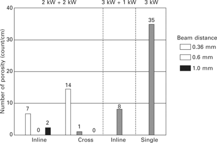
16.14 Effect of beam distance on formation of porosity in different beam configurations (aluminum alloy).
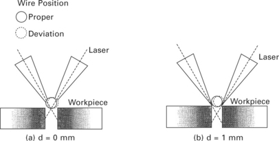
Another expected advantage of applying twin beams is their effect on gap tolerance as reported by Ohashi et al. [9]. In this study, two YAG lasers were used and applied through different optical lines and both tandem and parallel laser beam configurations were applied. In the case without a filler wire, the parallel beam configuration had a greater tolerance than the tandem beam configuration, as shown in Fig. 16.16. Figure 16.17 shows cross sections obtained by applying the twin beam to a filler wire. Welding was available until the gap dropped below 1.6 mm for both the tandem beam and the parallel beam configurations. Where the gap was much larger, however, the energy of the laser beam was spent in heating the wire and the heat input into the base material therefore decreased. One solution to the problem is shown in Fig. 16.18. In cases using the parallel beam configuration, the irradiation area can be controlled by changing the beam distance. By using this technique, heat input at the bottom of the gap is increased and gap tolerance is effectively improved.
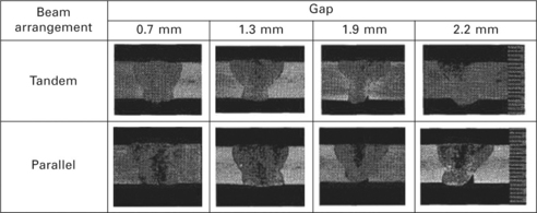
16.17 Effect of filler wire on gap tolerance in different configurations of twin-beam laser (base metal; type 304 stainless steel, filler wire; SUS308Y, dia = 12 mm).
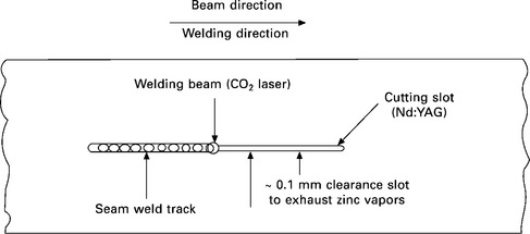
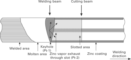
Iqbal et al. [10], [11] applied the twin-beam technique for the welding of zinc coated steel. An Nd:YAG laser was used as an advancing beam and a CO2 laser was used as the following one in the tandem twin-beam configuration. The front beam (Nd:YAG laser) cut a slot to remove the zinc coating and the back beam (CO2 laser) welded a material as shown in Fig. 16.19. Figure 16.20 shows a schematic of the proposed welding method by the tandem twin-beam irradiation.
16.4.2 Dissimilar materials welding
The application of the twin-beam laser technique for dissimilar materials welding is described below [3]. In the majority of cases involving the welding of dissimilar materials, intermetallic phases are formed, which reduce the strength of the joint. In cases where the materials have very different melting temperatures, the formation of the intermetallic phase could be controlled using a solid-state–liquid-state reaction at the interface [12]. When there is only a minor difference in the melting temperature of the materials, however, such as in magnesium alloy/aluminum alloy dissimilar metals welding, the solid-state–liquid-state reaction cannot be achieved and the intermetallic phase can be easily formed in the molten pool. An alternative method for controlling the formation of the intermetallic phases will therefore be required.
AZ31B magnesium alloy and A5052-0 aluminum alloy plates of 1 mm in thickness were used in the present study. The Nd:YAG laser was used for welding with both single-beam and twin-beam with the parallel beam configuration that both beams were placed in perpendicular to the welding direction. Twin laser beams were obtained by splitting an original beam using a prism as shown in Fig. 16.1. In this study, the two wedge angles of the prism were 2° and 4°, which separated the beam distances into 0.87 and 1.60 mm, respectively. The welding configuration used is shown in Fig. 16.21. The laser was irradiated on the AZ31 plate, which was the upper plate of the lap joint configuration in the direct welding. The laser power used was 3 kW with CW.
Plate XVIII (between pages 328 and 329) shows cross sections of a weld pool for all welding configurations. The joint width and depth of the molten metal for the joints obtained are shown in Fig. 16.22. The weld bead width and depth of the molten metal slightly increased with a decrease in welding speed for single-beam welding and twin-beam welding with a 2° wedge prism. In the case of the twin beam with a 4° wedge prism, however, an increase in the depth of the molten metal was not significantly observed, but the weld width increased. Figure 16.23 shows the failure load and joining strength of the joints. It was found that an application of single-beam and twin-beam welding with a 2° wedge prism resulted in decreasing joining strength with a decrease in welding speed because deep penetration of the molten metal might cause the formation of thick intermetallic compounds. In the case of the twin-beam welding with a 4° wedge prism, however, the change in depth of the molten metal is very small resulting in an increase in the failure load and a negligible change in the joining strength even when the welding speed decreased.
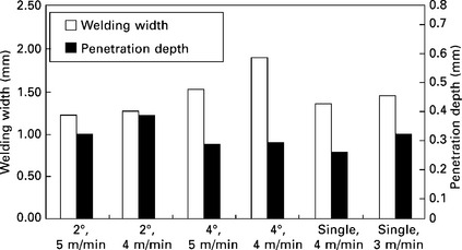
16.22 Effect of welding configuration on width and penetration depth of the weld pool in AZ31/A5052 dissimilar materials direct joint.
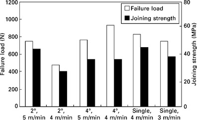
16.23 Effect of welding configuration on failure load and strength in AZ31/A5052 dissimilar materials direct joint.
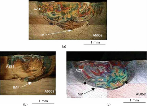
Plate XVIII Cross-sectional observations of AZ31/A5052 dissimilar materials direct joint: (a) single beam, (b) twin beam (wedge angle 2°) and (c) twin beam (wedge angle 4°).
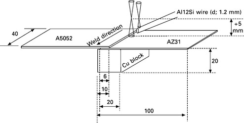
The failure load of the joints could be improved by applying the twin beam to direct welding as just described. An intermetallic phase was still formed at the interface, however, which affected the strength of the joint. In order to control the composition of the material at the interface, a filler metal was applied. The filler wire used was an Al12Si eutectic alloy with a diameter of 1.2 mm. The wire was positioned at the edge of the upper plate. Both the single beam and twin beam were used. In the case of twin beam when welding with a filler metal, the tandem beam configuration with two beams placed parallel to the welding direction was used. A5052 was placed as an upper plate irradiated by the laser beam. The laser power used was 3 kW. For the twin-beam welding, a 4° wedge prism was used to split an original beam. The intensity ratio between the forward beam and the following beam was 1:2. A schematic illustration of the welding configuration for twin-beam laser welding with a filler wire is shown in Fig. 16.24.
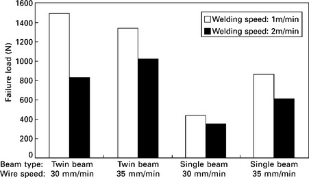
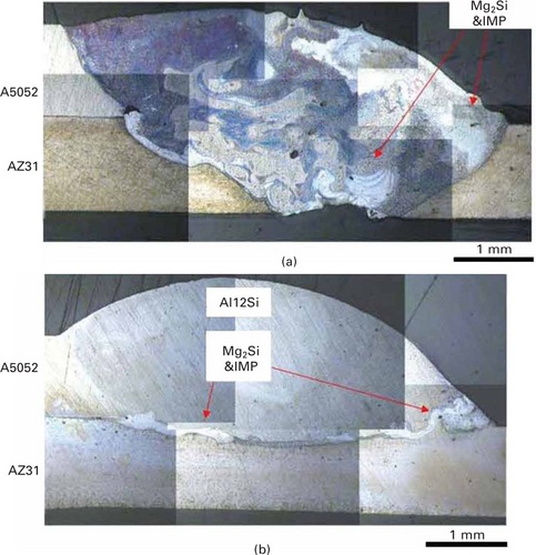
According to observations made by a high-speed camera during the twin-beam laser welding process, it was confirmed that the forward beam was used only for pre-heating without melting the base metal. Plate XIX (between pages 328 and 329) shows cross-sectional observations of the joints welded with the filler wire for both single- and twin-beam welding. Full penetration always occurred during single-beam irradiation, whereas only partial penetration was observed during twin-beam irradiation. At the interface between the filler metal and the base metals, Mg2Si and Al-Mg intermetallic phase was observed. Figure 16.25 shows the failure load of the joints welded with a filler wire. The failure load of the joints welded with the twin beam was higher than that of those welded with a single beam.
16.4.3 Surface modification
Laser cladding is a surface modification technique and has been used in applications such as preparing the valve sheet of an engine component in the motor industry. In the process, particles are mixed together with the molten metal at the surface. A composite or alloying material is then formed to improve the properties of the original material such as its ability to withstand corrosion, temperature and wear, etc. In this section, laser cladding using twin-beam irradiation on a magnesium alloy is discussed.
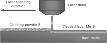
The material and particle used for the surface modification were an AZ31 magnesium alloy and Si. These can be expected to form Mg2Si, which will increase the hardness and wear resistance of the alloy. An Nd:YAG laser was used and the beam was split by a prism with a wedge angle of 4°. Two configurations of twin beams were applied: (1) the parallel beam in which two beams were placed perpendicular to the laser scanning direction, and (2) the tandem beam in which two beams were placed parallel to the laser scanning direction. A Si powder layer with a thickness of 0.3 mm was placed on the surface of the base metal before irradiation of the laser beam. A schematic illustration of the laser cladding experiment is shown in Fig. 16.26.
The modified cladded surfaces following the single-beam and twin-beam irradiation are shown in Fig. 16.27. Two welding beads can clearly be observed in the case of the surface cladding using parallel beams. This separation of the beads becomes more apparent as the scanning speed increases. The bead width of the parallel beam surface was also small compared with that in the single beam case. Cross-sectional observations of the materials modified with single- and twin-beam irradiation are shown in Plate XX (between pages 328 and 329). In the case of the parallel twin-beam irradiation with lower laser scanning speed, Si powders were mixed well. The amount of non-melt Si powders increased with the laser scanning speed, however. The cross sections show that the depth of the molten pool created by the twin-beam irradiation was shallow compared with that created by single-beam irradiation. This was due to the low energy density of the laser beams in the twin-beam irradiation. If attention was paid to the one molten line, the Si compound was distributed along the molten pool, but the mixing was not well done inside the molten pool. In the middle section of the irradiation points of the two beams, granular-like Si compound was observed. It is speculated that the duration time for maintaining the molten pool decreases in the case of parallel twin-beam irradiation under the higher scanning speed conditions.
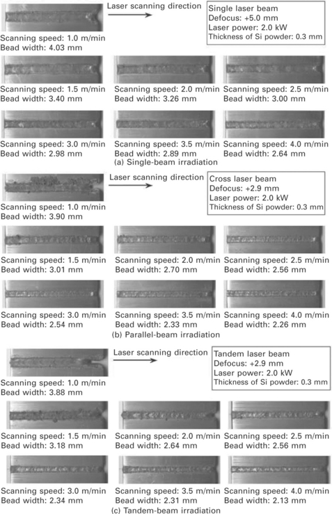
16.27 Appearance of cladding surface: (a) single-beam irradiation, (b) parallel-beam irradiation, (c) tandem-beam irradiation.
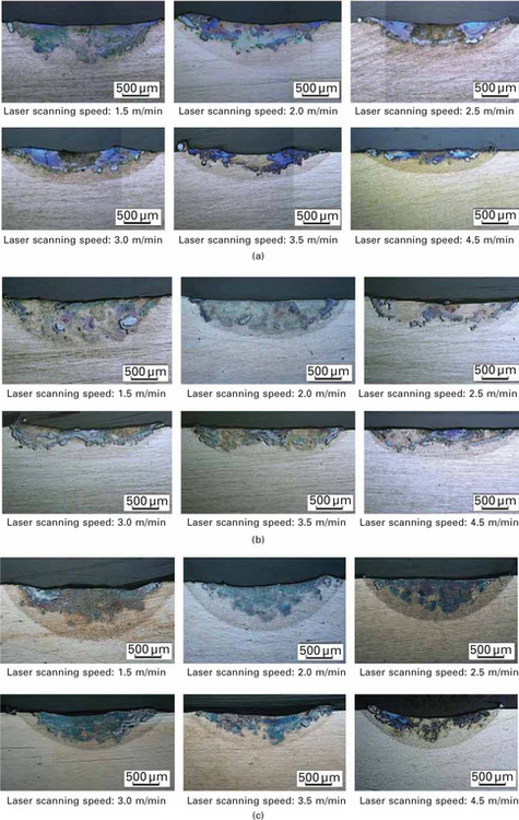
Plate XX Cross-sectional observations of cladded specimen: (a) single-beam irradiation, (b) parallel-beam irradiation and (c) tandem-beam irradiation.
Observation of a weld bead created with the tandem-beam irradiation is shown in Fig. 16.27(c). The bead width was narrower with the parallel-beam irradiation when compared with the single-beam irradiation as previously mentioned. Bead width was also narrower in the case of the tandem-beam irradiation. The smooth surface of the material following irradiation with the tandem beams was obtained due to the long laser irradiation time. Plate XX (between pages 328 and 329) shows the cross section of the part subjected to the tandem laser beam cladding. The molten pool shape was completely different between the single-beam irradiation and the parallel twin-beam irradiation. In the cases of the single-beam irradiation and the parallel twin-beam irradiation, Si particles were found around the bottom of the molten pool and a lack of Si was also observed in the middle section. Contrastingly, in the case of the tandem-beam irradiation, Si particles were uniformly distributed in the molten pool. However, the increase in scanning speed meant that the molten metal and Si particles were not thoroughly mixed. Inside the molten pool, Mg2Si was formed significantly. In the case of the tandem-beam irradiation, the following beam effectively mixed the material melted by the irradiation of the advancing beam and the total duration time of melting was much longer than that of either the single or parallel twin-beam irradiation. The tandem twin-beam irradiation is an effective method of inducing flow activity in the molten pool. Clusters of Si particles were not found around the bottom of the molten pool in laser clad material which had been irradiated using the tandem twin beam. Plate XXI (between pages 328 and 329) shows the cross section and Si distribution of the material after laser cladding using the tandem twin-beam irradiation. Around the interface between the base metal and the molten pool, the Si content continuously increased from the base metal to inside the molten pool. Plate XXII (between pages 328 and 329) shows the enlarged images of Plate XXI. A large number of Mg2Si particles were formed. This was due to effective and thorough mixing of the molten metal induced by the tandem twin-beam irradiation.
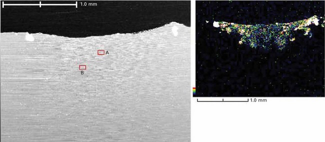
Plate XXI Scanning electron microscope image and Si distribution at molten zone obtained by the tandem-beam cladding.
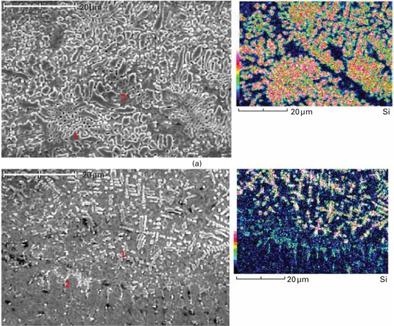
Plate XXII Enlarged images of Plate XXI showing Si distribution: (a) area ‘A’ and (b) area ‘B’.
16.4.4 Cutting
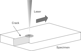
A diamond tool is conventionally used to cut brittle materials, since it provides a high cutting quality and productivity [13]. The unavoidable disadvantages of diamond tools, however, include the occurrence of pollution for the material and working environment, micro-cracking and a loss of the material cut due to finite thickness of the tool. Conventional laser cutting of metals usually causes the melting and vaporization of the material, which not only would not solve the conventional mechanical cutting process caused by diamond tools, but would add thermal distortion and residual stress in the cut material to the problem. The laser cutting method studied in this section avoids this melting process, however. A basic idea for the method is schematically shown in Fig. 16.28. The local thermal stress is generated ahead of the crack tip by laser irradiation without melting the material, which is a driving force for crack propagation. The method is a possible solution to the aforementioned brittle material cutting issues, which have been studied analytically as well as experimentally in previous works. Practical application of this new laser method is still limited, however, due to the difficulty of controlling crack propagation behavior. In this section, the applicability of twin-beam irradiation for laser cutting as a method of controlling crack propagation behavior is presented based on the results of FEM analysis.
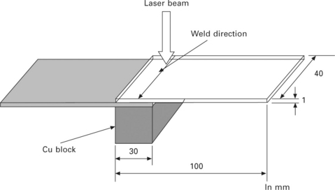
A soda-lime glass with a thickness of 1.77 mm was used as an example of a brittle material. A starter notch was introduced using a diamond cutter at the starting point of laser irradiation. The laser equipment used was a Nd:YAG laser. The laser power and scanning speed were fixed at 500 W with continuous wave (CW) and 20 mm/s, respectively. The focusing point was adjusted to 3 mm up from the specimen surface to avoid the melting of the material. The laser beam began irradiating from the edge of specimen and continued to scan straight up to 10 mm and then changed the scanning direction of the laser beam to angles, ψ = 30, 60 and 90 degrees.
Figure 16.29 shows an example of a laser cutting line for ψ = 90°. The figure shows that the laser cutting line was swerved from the original laser scanning line. The crack propagation direction did not follow the laser scanning direction from 1.4 mm before the turning point of laser scanning direction. Similar results were obtained at other angles too. It is considered that the crack follows 1.4 mm behind the laser spot and the crack propagation direction is changed immediately when the laser scanning direction is changed.
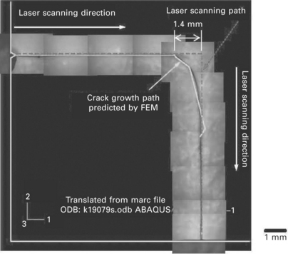
16.29 Comparison of crack path between experimental and analytical results for single-beam laser cutting at ψ = 90°.
The crack propagation behavior was estimated using FEM analysis under the same condition of laser irradiation as the experiment shown above. In the crack path estimation, a criterion for crack propagation is assumed as Kθmax > Kc, where Kθmax is a stress intensity factor for the maximum tangential stress generated by the laser irradiation, and Kc is the fracture toughness of the material. The crack propagation direction is also assumed to be the direction of Kθmax. The crack propagation path obtained using FEM analysis is also shown in Fig. 16.29. The crack propagation behavior estimated by the FEM analysis corresponds well with the experimental results. A stress intensity factor for the maximum tangential stress, Kθmax, is therefore considered to be a dominant parameter for crack propagation. Crack growth direction can be controlled by controlling the maximum tangential stress, i.e. controlling the thermal stress distribution induced by the laser irradiation.
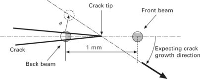
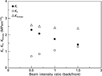
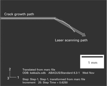
In order to control the crack growth direction during the laser cutting, a twin-beam laser technique was studied using FEM analysis. Laser cutting using the tandem twin beam is schematically shown in Fig. 16.30. The two beams are placed parallel to the laser scanning direction, which is called the tandem twin-beam configuration as shown in the figure, and the position of the crack tip is in between the front and the back beams. The back beam moves toward ϕ, which is equal to the expected angle for the change of crack path, when the crack tip reaches the expected position for changing the crack propagation direction. The expected angle for the change of crack path was 30° in this analysis. The distance between the front and the back beams was 1 mm with a laser spot radius of 0.35 mm. Figure 16.31 shows the change in stress intensity factors for Mode I and Mode II, i.e. KI and KII, due to the change in the intensity ratio between the front and the back beams. The mode ratio KI/KII is changed depending on the beam intensity ratio. This means that the direction of the maximum tangential stress can be controlled by the twin-beam irradiation. Figure 16.32 shows an example of crack growth behavior estimated by FEM analysis for the tandem-beam irradiation with intensity ratio of 1:2 (front:back) at an expected angle for crack growth of 30°. As can be seen from the figure, the crack propagation direction followed the laser scanning direction. The twin-beam method could therefore control the crack propagation direction by changing the beam intensity ratio. Parallel twin-beam laser cutting, where two beams lined perpendicular to the laser scanning direction, was also studied [14], but the result indicated that it was not an effective method of controlling the crack path.
16.5 Conclusion
The application of twin laser beams allows for the possibility of overcoming limitations in laser processing with single-beam laser irradiation due to the increase in processing parameters, such as a combination of the wavelengths of two beams, beam distance and beam configuration, etc. A simple increase in laser power by using two beams is less important as an application than the twin beam, because the advances in the technology of laser welding apparatus with its cost reduction have been significant in recent years. Particular phenomena induced by the twin-beam irradiation, such as the increase in laser absorptivity, the active convection of molten metal, the increase in gap tolerance, and the control of thermal stress are all introduced in this chapter. Combining a different heat source with a laser beam is also being actively developed as a hybrid welding technique. Theoretical and numerical studies as well as experimental study are required to develop new applications for twin-beam laser welding and laser processing technology.
16.6 References
[1] Sakamoto, H., Iwase, T., Shibata, K. Effect of Twin Spot Beam Arrangement on Energy Coupling During Welding – Study of Twin Spot Nd:YAG Laser Welding of Aluminum Alloys (Rep. 3). Quarterly Journal of The Japan Welding Society. 2003; 21(4):501–506.
[2] Chen, J., Mutoh, Y., Miyashita, Y., Koide, D., Borrisutthekul, R. Computational Investigation on Molten Pool of Single and Twin Beam Laser Welding. Journal of Solid Mechanics and Materials Engineering. 2007; 1(5):624–634.
[3] Miyashita, Y., Borrisutthekul, R., Chen, J., Mutoh, Y. Application of Twin Laser Beam on AZ31/A5052 Dissimilar Metals Welding. Key Engineering Materials. 2007; 353–358:1956–1959.
[4] Fujinaga, S., Miura, H., Narikiyo, T., Katayama, S., Ohmori, A. Welding Characteristics with Three Nd:YAG Laser Beams Transmitted through Single Optical Fiber. Quarterly Journal of The Japan Welding Society. 1998; 16(4):445–452.
[5] Shibata, K., Iwase, T., Sakamoto, H., Seto, N., Matsunawa, A., Hohenberger, B., Mueller, M., Dausinger, F. Study on Keyhole Behavior in Twin Spot Beam Welding of Aluminum Alloys by Means of X-ray Observation – Study of Twin Spot Nd:YAG Laser Welding of Aluminum Alloys (Rep. 1). Quarterly Journal of The Japan Welding Society. 2003; 21(2):204–212.
[6] Jonghyan, M., Mizutani, M., Katayama, S., Matsunawa, A. Melting Characteristics of Various Metals with Combined Lasers of Different Wavelength. Quarterly Journal of The Japan Welding Society. 2002; 20(4):449–457.
[7] Shibata, K., Iwase, T., Sakamoto, H. Effect of Twin Spot Beam Configration on Overlap Joints Welding – Study of Twin Spot Nd:YAG Laser Welding of Aluminum Alloys (Rep. 2). Quarterly Journal of The Japan Welding Society. 2003; 21(2):213–218.
[8] Hayashi, T., Matsubayashi, K., Katayama, S., Abe, N., Matsunawa, A., Ohmori, A. Reduction Mechanism of Porosity in Tandem Twin-Spot Laser Welding of Stainless Steel. Quarterly Journal of The Japan Welding Society. 2002; 20(2):228–236.
[9] Ohashi, R., Fujinaga, S., Katayama, S., Matsunawa, A. Extension of Gap Tolerance in Square Butt Joint Welding with Nd:YAG Laser. Quarterly Journal of The Japan Welding Society. 2003; 21(1):25–32.
[10] Iqbal, S., Gualini, M. M. S., Grassi, F. Laser Welding of Zinc-Coated Steel with Tandem Beams: Analysis And Comparison. Journal of Materials Processing Technology. 2007; 184:12–18.
[11] Iqbal, S., Gualini, M. M. S., ur Rehman, A. Dual Beam Method for Laser Welding of Galvanized Steel: Experimentation and Prospect. Optics & Laser Technology. 2010; 42:93–98.
[12] Miyashita, Y., Nakagawa, I., Xu, J. -Q., Mutoh, Y., Akahori, M., Okumura, H. Laser Welding of Dissimilar Metals Joint Aided by Unsteady Thermal Convection Boundary Element Method Analysis. Quarterly Journal of the Japan Welding Society. 2005; 23(1):16–24.
[13] Miyashita, Y., Mogi, M., Hasegawa, H., Sujatanond, S., Mutoh, Y. Study on a Controlling Method for Crack Nucleation and Propagation Behavior in Laser Cutting of Glass. Journal of Solid Mechanics and Materials Engineering. 2008; 2(12):1555–1566.
[14] Miyashita, Y., Hasegawa, H., Mutoh, Y. Japan. Laser Cutting of a Brittle Material by Controlling Crack Growth Behavior based on Fracture Mechanics (in Japanese). Proceedings of 53rd Annual Meeting of Society of Materials Science. 2004:93–94.

