Applications of robotics in laser welding
Abstract:
This chapter describes how seam-tracking sensors can be integrated in a robotic laser welding system for automatic teaching of the seam trajectory as well as for correcting small errors from a pre-defined seam trajectory. Calibration procedures are required to derive accurate transformations of laser and sensor tool frames relative to each other or relative to the robot flange. A tool calibration procedure is described that involves movements of the tool above a special calibration object. The accuracy of this procedure is influenced by errors in the robot movement. Therefore, another calibration procedure is developed, which is a direct measurement of the sensor tool frame relative to the laser tool frame. A trajectory-based control approach is presented for real-time seam tracking, where a seam-tracking sensor measures ahead of the laser focal point. In this control approach, sensor measurements are related to the robot position to build a geometric seam trajectory, which is followed by the laser focal point.
14.1 Introduction: key issues in robotic laser welding
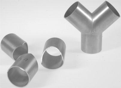
In the manufacturing industry, many types of joints are used for laser welding. This chapter considers continuous seam welding of 3D seams, where the handling of the laser welding head is done with robotic manipulators. Six-axis robotic manipulators are relatively cheap and flexible as they can reach more complicated seams, opening a wider range of applications. A typical example of a 3D product where robotic laser welding may be applied can be found in Fig. 14.1.
Unfortunately, the absolute accuracy of robotic manipulators does not meet the accuracy demands of laser welding. Therefore, welding of 3D seams is not a trivial extension to seam welding of two-dimensional seams. Accurate manual programming of these welding trajectories is time-consuming. CAD/ CAM or off-line programming software may be used to generate the welding trajectories, but it remains difficult to accurately match such a trajectory with the actual seam trajectory in the work cell. The important accuracy requirement is the accuracy of the laser focal point relative to the product. This accuracy is influenced by the robotic manipulator and the product, e.g. product tolerances and clamping errors. For laser welding of steel sheets using a laser spot diameter of 0.45 mm and a focal length of 150 mm, it was found that a lateral tolerance of ± 0.2 mm has to be satisfied in order to avoid weld quality degradation (Duley, 1999; Kang et al., 2008), which has to be achieved at welding speeds up to 250 mm/s.
To cope with these issues, seam-tracking sensors that measure the seam trajectory close to the laser focal spot are required (Huissoon, 2002). The requirements for the positioning accuracy of the laser beam on the seam, the integration and the automation of the process will be fulfilled using seam-tracking sensors. Many different sensing techniques for measuring three-dimensional information can be distinguished, e.g. inductive measurements, range measurement using different patterns, surface orientation measurement using different surfaces, optical triangulation, etc. (Regaard et al, 2009). Sensors based on optical triangulation with structured light are used most often as they provide accurate 3D information at a considerable distance from the product surface. Optical triangulation can be divided into two parts: beam scanning and pattern projecting. In beam scanning, a projector and detector are used that are simultaneously scanning the surface. Pattern projecting is done with different structures, e.g. one or multiple lines, circles, crosses or triangles. A two-dimensional camera observes the structures, and features are detected using image processing. The sensor uses a laser diode to project a single line of laser light on the surface at a certain angle. A camera observes the diffuse reflection of the laser diode on the surface at a different angle. Deviations on the surface will result in deviations on the camera image, which are detected. Several features are detected from the camera, e.g. the 3D position and an orientation angle.
A considerable amount of work preparation time consists of programming the robot for a new welding job. This can be decreased by using a seam-tracking sensor for automatic teaching of the seam-trajectory. Once a seam has been taught in this way, it can be welded in any number of products as long as no modifications of this trajectory occur, e.g. due to clamping errors, product tolerances, heat deviation errors, etc. In cases where modifications of this trajectory do occur, the sensor can be used to correct small errors from a pre-defined seam trajectory, using sensor measurements obtained some distance ahead of the laser focal point. Both the sensor and laser welding head are tools that are attached to the robot flange. The sensor measures relative to its own coordinate frame, but the corrections need to be applied in the laser coordinate frame. The transformations between these coordinate frames and the robot flange need to be accurately calibrated.
This chapter describes how such sensors can be integrated in a robotic laser welding system. A typical connection topology with the main components used in a sensor-guided robotic laser welding system is given in Section 14.2. Different coordinate frames are described in Section 14.3. From a scientific point of view, two major subjects are of particular interest: tool calibration (Section 14.4) and seam teaching/tracking (Section 14.5); for the latter a trajectory-based control architecture is presented (Section 14.6), which allows the construction of the robot trajectory during the robot motion. Finally, integration issues and future trends are discussed in Section 14.7.
14.2 Connection topology
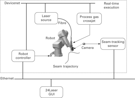
Common components in a sensor-guided robotic laser welding system are a robot controller, seam-tracking sensor, laser source and a fibre to guide the laser light to a welding head, where it is focused on the product. Process gas protects the melt pool from oxidation and a crossjet protects the focusing lens in the welding head from process spatters. Figure 14.2 shows the components used in a typical sensor-guided robotic laser welding system.
All the components inside the dotted box require real-time execution. The robot controller controls not only the robot motion but also the other equipment during laser welding. The laser, crossjet and process gas have to be switched on and off synchronously with the robot motion. An industrial Devicenet bus system is used here, but in general many different bus systems exist that are equally well suited. The seam-tracking sensor is located within the real-time execution box, as its measurements must be synchronised with the measurements of the robot joint angles to get accurate results at the high speeds that occur in a robotic laser welding system (De Graaf et al, 2005).
The system operator can control the system using a (graphical) user interface (GUI) called ‘24Laser’, which may be present on the teach pendent of the robot controller or on a separate computer. The GUI is used to prepare and start a laser welding job. Furthermore, it may contain various algorithms for seam teaching, real-time seam tracking and tool calibration.
14.3 Coordinate frames and transformations
An overview of the coordinate frames and transformations that can be distinguished in a sensor-guided robotic welding system can be found in Nayak and Ray (1993). Their overview is generalised, by adding a station frame M and a product frame H.
A transformation describes the location (position and orientation) of a frame with respect to a reference frame. Transformations are indicated by the symbol T with a leading superscript, that defines the reference frame they refer to. The leading subscript defines the frame they describe, e.g. transformation ABT describes frame B with respect to frame A.
In the literature, 4 × 4 homogeneous transformation matrices are often used to describe transformations (Craig, 1986; Khalil and Dombre, 2002).
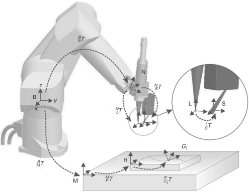
They consist of a 3 × 3 rotation matrix and 3D position vector. Homogeneous transformation matrices have some useful properties, e.g. different transformations can be added using matrix multiplication. The following frames are defined in Fig. 14.3:
• B: Base or world frame. This frame is attached to the robot base and does not move with respect to the environment.
• N: Null frame. The null frame is located at the robot end-effector or the end of the robot flange. The null frame is described with respect to the base frame by coordinate transformation BNT, which is a function of the joint positions of the robot arm (forward kinematics or direct geometric model).
• L: Laser tool frame. The laser tool frame is located at the focal point of the laser beam. The z-axis of this frame coincides with the laser beam axis. Because the laser beam is axi-symmetric, the direction of the x-axis is arbitrary, unless the symmetry is broken due to, e.g., the presence of peripheral equipment. Without loss of generality it will be chosen in the direction of the sensor tool frame. The transformation NLT describes the laser tool frame with respect to the null frame. This is a fixed transformation determined by the geometry of the welding head.
• S: Sensor tool frame. The seam-tracking sensor is fixed to the welding head and therefore indirectly to the robot flange. The transformation NST describes the sensor tool frame with respect to the null frame. Note that, because both transformations are fixed, this transformation can also be described with respect to the Laser tool frame instead of the Null frame by transformation LST.
• M: Station frame. The station frame is the base of the station or worktable a product is attached to. It is possible that the product is clamped on a manipulator which moves the product with respect to the base frame. In that case the transformation BMT describes the station frame with respect to the base frame and depends on the joint values of the manipulator.
• H: Product frame. This frame is located on a product. The transformation MHT describes the product frame with respect to the station frame. This frame is useful if a series of similar products are welded on different locations of a station.
• G: Seam frame. Every discrete point on a seam can be described with a different coordinate frame. The transformation HGT describes a seam frame with respect to the product frame.
• T: Robotic tool frame. A general robot movement is specified by the movement of a robotic tool frame T, which can be either the sensor tool S or laser tool L. Some equations used in this chapter account for either S or L. In that case, the symbol T will be used.
• F: Robotic frame. A general robot movement is specified with respect to a frame F, which can be the base frame B, station frame M, product frame H or seam frame G. The symbol F will be used in general equations that account for all of these frames.
In many cases, an external manipulator is not present and a series of products will only be welded at a fixed location in the work cell. Both transformations BMT and MHT can then be chosen as unity. A seam frame G is then described with respect to the robot base with transformation BGT.
14.4 Tool calibration
Generic work on calibration of wrist-mounted robotic sensors has been performed since the late 1980s and early 1990s. It is often referred to as the hand-eye calibration or sensor mount registration problem. Homogeneous transformation equations of the form AX = XB are solved, where X represents the unknown tool transformation, A is a pre-defined movement relative to the robot flange and B is the measured change in tool coordinates. It was first addressed by Chou and Kamel (1988), although several other approaches for obtaining a solution have been presented by Shiu and Ahmad (1989), Tsai and Lenz (1989), Zhuang and Shiu (1993), Park and Martin (1994), Lee and Ro (1996), Lu et al. (1996), Thorne (1999), Daniilidis (1999) and Huissoon (2002).
In most of the above-mentioned references, mathematical procedures are presented to solve the generic calibration problem of wrist-mounted sensors. In these publications, the procedures are verified using simulation data only. Daniilidis (1999) and Huissoon (2002) are the only ones who present experimental results. A major drawback in the presented simulations is that in all publications, except Lee and Ro (1996), only the influence of stochastic errors (measurement noise) is considered and not the influence of systematic errors originating from robot geometric nonlinearities, optical deviations, sensor reflections, etc. In De Graaf (2007), the influence of such systematic errors on the tool calibration procedures is analysed in more detail, which shows that the accuracy that can be achieved with these tool calibration procedures is limited to approximately 1 mm.
Huissoon (2002) is the only author to directly apply the tool calibration methods to robotic laser welding. However, he does not give results of the sensor tool calibration procedure he uses. No publications were found that apply the calibration procedures to a laser welding head without a sensor. A calibration procedure for a laser welding head is presented in Section 14.4.1, which uses the coaxial camera attached to the welding head and a calibration object.
In a sensor-guided robotic laser welding system, the sensor measures relative to its coordinate system (S), but the measurements are applied in the laser coordinate frame (L). According to Fig. 14.2 the transformation LGT that describes the transformation between laser frame L and seam frame G, representing the deviation of the laser focal point and the seam trajectory, can be computed as:
where LST is a fixed geometrical transformation from the laser frame to the sensor frame and SGT represents a measured location on the seam trajectory relative to the sensor frame S. To position the laser spot accurately on the seam, both of these transformations need to be accurately known (< 0.2 mm).
Robot movements can be defined relative to the flange frame N or relative to any tool frame T, which can be S or L. When robot movements are defined relative to the sensor or the laser tool frame, the transformations NLT (which represents the transformation from flange to laser frame) and NST (which represents the transformation from flange to sensor frame) need to be known respectively. According to Fig. 14.2, one of the transformations LST, NLT and NST can be computed if the other two are known using:
The most important transformation that needs to be accurately known is the transformation LST, which can be computed using Eq. [14.2] from the result of a laser tool calibration procedure and a sensor tool calibration procedure. Because both NLT and NST cannot be accurately determined due to geometric robot errors, a combined calibration procedure is presented in Section 14.4.2, where the transformation LST is determined by means of a direct measurement that does not involve robot movements. Therefore, errors in the robot geometric model do not influence the measurement, which makes this method much more accurate.
14.4.1 Laser tool calibration
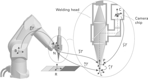
The laser tool calibration procedure uses a coaxial CCD camera, which is attached to the welding head. The setup with coordinate frames used are shown in Fig. 14.4.
For the calibration procedure, the following additional frames are defined:
• C: Camera frame. The surface normal of the camera chip coincides with the z-axis of frame C and with the optical axis of the laser beam.
• R: Reference frame. A calibration object with a mirror, a pinhole with a light emitting diode (LED) and a plate of black anodised aluminium is placed in the robot work space. The origin of frame R is located at the pinhole providing a fixed point in robot space that can be measured by the camera.
• P: Pilot laser frame. A low-power pilot laser will be applied, using the same optical fibre as the high power Nd:YAG laser. The projection of the laser light spot from this pilot laser on the camera chip will be used for focal measurements.
In the calibration procedure, the pilot laser will be used. The transformation NLT can be split according to:
The pilot laser and Nd:YAG laser share the same optical axis. The rotation of these frames around the optical axis is assumed to be identical and PLT is a transformation that represents a pure translation with a distance d along the z-axis. The distance d only depends on the optical system of the welding head. If the optical system does not change, it needs to be determined once. In the calibration procedure the transformation NPT from flange frame to pilot frame will be determined and finally a procedure is outlined to determine distance d. Using Eq. [14.3] and known distance d, the transformation NLT from flange frame to laser frame is easily computed.
The camera may be rotated freely around the optical axis. The orientation between the laser frame or the pilot frame and the camera frame is therefore related as:
where rot(z, ϕ) is a rotation matrix that represents a pure rotation around the z-axis with an angle ϕ.
The camera is used to observe the pinhole in the calibration object or a reflection of the pilot laser beam in the mirror. In either case, the camera image shows a light spot in a dark background (Fig. 14.5). Using basic image processing (Van der Heijden, 1994), the centre of gravity of the light spot and the number of pixels of the light spot are determined. Details of the image processing algorithms used can be found in Van Tienhoven (2004). The position CP in pixels of the centre of this light spot relative to the camera frame C is denoted by
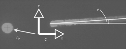
14.5 Typical camera measurement during the laser tool calibration procedure. Note that the angle of the line is irrelevant for the laser tool calibration, but used later in the combined calibration procedure of Section 14.4.2.
The camera measures two degrees-of-freedom. The orientation of the camera frame and the pilot frame are related through Eq. [14.4]. If frame P moves from location Pi to location Pi+1, the camera frame moves from location Ci to location Ci+1. The positions between the frame movements are then related as
where 1/c is a scaling factor to convert from camera pixels to millimetres. The camera pixels may not be square in which case different ratios 1/cx and 1/cy are used for the camera x-direction and y-direction.
To make sure that the observed object stays within the range of the camera, movements are defined relative to a nominal pilot frame Pn, which is an estimation of the actual pilot laser frame Pa. The maximum allowable difference between the nominal frame and the actual frame depends on the field-of-view of the camera. In practice, this is large enough to start the calibration procedure with a user-defined nominal tool transformation NPnT that is known from the dimensions of the welding head.
The generic AX= XB equation is written relative to the nominal pilot frame Pn, instead of the flange frame N, where A is a prescribed transformation (movement) in the nominal pilot frame and B is a measured transformation in the actual pilot frame. Transformation B cannot be completely measured because a 2D camera is used. By choosing the prescribed movement A in a suitable way, parts of the AX= XB equation can be solved in subsequent steps. During the calibration procedure, the translation and rotation components of X are solved separately using the following procedure:
• Determination of the pilot frame orientation: A number of robot movements are made that are defined as pure translations in the nominal pilot frame, while observing the pinhole in the camera image to find the rotation matrix PnPaR. During this calibration step, the ratios cx and cy to convert from camera pixels to millimetres are computed as well as the camera rotation angle ϕ.
• Determination of the surface normal and focal position: The calibration object is placed arbitrarily in the robot workspace. In this step the optical axis of the welding head and the surface normal of the calibration object are aligned by projecting the pilot laser on the camera image using the mirror and moving the pilot frame along its optical axis. Furthermore, the focal position of the pilot laser on the camera will be determined.
• Determination of pilot frame position. A number of robot movements are made that are defined as pure rotations in the nominal pilot frame, while observing the pinhole in the camera image to find the position vector PnPaP.
• Determination of the difference d in focal height between the pilot frame as it is focused on the camera chip and the Nd:YAG frame as it is focused on the surface. This is done by making spot welds on a plate of anodised aluminium attached to the calibration object (in the same plane as the mirror) and determining the height corresponding to the smallest spot relative to the pilot focal position.
Details of the algorithms used and experimental results can be found in Van Tienhoven (2004) and De Graaf (2007).
14.4.2 Combined calibration
To be able to compute the sensor pose relative to a calibration object from a single sensor measurement, Huissoon (2002) proposes to add edges to such a calibration object. He describes a calibration object with three edges and a mathematical approach for computing the sensor pose relative to the calibration object. For this task, a calibration object with two edges is used as this is sufficient to determine the complete sensor pose. This calibration object offers improved accuracy and noise suppression over Huissoon's object. A more complex nonlinear matrix equation has to be solved however, which Huissoon avoids by using an additional edge feature.
The two upper edges of the calibration object give three lines in a sensor image (Fig. 14.6). From the lines in the sensor image, the intersections of the edges of the calibration object with the laser plane can be computed. This is done by fitting lines through the sensor data and computing their intersections P1, P2 and P3 as indicated in Fig. 14.6(b). Note that P1 is a virtual intersection that is constructed by extrapolating the outer line parts. These intersections are 3D vectors in the sensor frame, where two coordinates are measured in the CMOS image and the third coordinate is computed using the known diode angle of the sensor. Hence, there are a total number of nine parameters, where six of them are independent. Every sensor pose yields a unique combination of these parameters. The algorithms for computing the sensor pose from the intersections as well as experimental results can be found in De Graaf (2007).
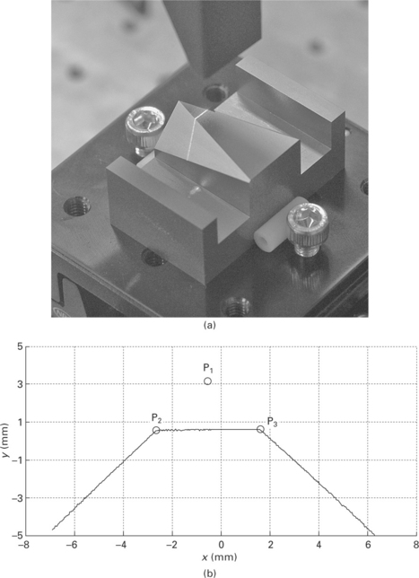
14.6 (a) Sensor positioned above the calibration object. (b) Typical sensor profile on the calibration object.
In order to measure the transformation LST, the two calibration objects that are used in the sensor and laser tool calibration procedure are combined in a single calibration object (Fig. 14.7). From this figure, it can be derived that the transformation LST is computed as:
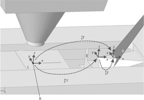
14.7 Laser and sensor positioned above the combined calibration object. Note that in this figure, frame L (attached to the welding head) overlaps frame R (attached to a pinhole in the calibration object), which is not generally the case.
The sensor calibration object has its own frame E and is mounted in such a way that the transformation RET is known from the geometry of the object. The transformation EST can be measured using the measurement method described in De Graaf (2007). The only unknown transformation is LRT, which will be derived next.
After the laser tool calibration procedure has been performed, a number of important conditions are determined:
1. The welding head is positioned normal to the calibration object.
2. The origin of the laser frame L has been determined in the camera image, so the position of the light spot can be measured relative to frame L.
3. The focal position of the welding head is positioned at the surface of the calibration object.
4. The scaling factors cx and cy from camera pixels to millimetres are determined.
These conditions will be used to determine transformation LRT. The optical axis of the welding head is normal to the calibration object (condition 1). Using condition 2, 3 and 4, it is known that transformation LRT can be determined from several features in the camera image, using the scaling factor cx and cy that were obtained during the laser tool calibration procedure.
The position of a spot and the orientation of a line in the camera image (Fig. 14.7) are needed to determine transformation LRT. Image processing algorithms and experimental results are beyond the scope of this chapter and can be found in De Graaf (2007).
14.5 Seam teaching and tracking
Two strategies are distinguished for sensor-guided robotic laser welding:
1. Teaching of the seam trajectory with the sensor in a first step (seam teaching) and laser welding in a second step.
2. Real-time seam tracking during laser welding. When the sensor is mounted some distance in front of the laser focal point, it can measure the seam trajectory and let the laser focal point track the measured trajectory in the same movement.
Seam teaching (method 1) has the advantage that it can be performed using point-to-point movements, where the robot stabilises after every step. This increases the accuracy as dynamic robot behaviour and synchronisation errors can be avoided.
In a production environment, method 2 would be preferred as it is faster and thus saves time and money. The seam-tracking sensor measures relative to its own coordinate frame (which is attached to the end-effector of the robot arm). Therefore its measurements cannot be directly used during a robot movement. The sensor measurements will only be useful if the Cartesian location of the sensor frame in the robot workspace (computed from the robot joint angles) is known at the same time. This can be accomplished in two ways:
• Let the robot make a movement and wait until it stabilises. Because the robot is stabilised the location of the sensor frame in the robot workspace does not change in time. Then, a sensor measurement can be easily related to the corresponding robot position.
• When a sensor measurement is obtained during the robot motion, the time axes of the robot and the sensor need to be synchronised. If these are synchronised the robot joints can be interpolated to match the sensor measurement with the robot joints or vice versa.
Robot-sensor synchronisation can easily be achieved for a simple external sensor (like a LVDT), where the sensor operates continuously and is interfaced directly to the robot, because the sensor data is immediately available when the robot needs it. Synchronisation becomes more challenging when complex sensor systems, like camera-based sensors with their own real-time clock, are used (De Graaf et al., 2005).
Seam teaching for arc welding has been regarded as being solved by many authors (e.g. Nayak and Ray, 1993). They focus on ways to use sensor information for real-time seam tracking and job planning. Most publications apply seam tracking to robotic arc welding, where the accuracy requirements (± 1 mm) are less stringent than for laser welding. Two publications (Andersen, 2001; Fridenfalk and Bolmsjö, (2003) apply seam tracking to the application of robotic laser welding. Unfortunately, Andersen (2001) gives no technical details of his algorithms. Fridenfalk and Bolmsjö (2003) describe their algorithm but do not pay much attention to robot integration aspects (e.g., robot-sensor synchronisation). The inaccuracy of their system (± 2 mm) is much larger than the 0.2 mm that is aimed at for laser welding of seams.
No publications were found that analyse the influence of various error sources (e.g., robot geometric errors) on seam teaching and seam tracking. The influence of these error sources on seam teaching and seam tracking cannot be underestimated, as shown in De Graaf (2007).
14.6 Trajectory-based control
To use a sensor for real-time seam tracking, a deep integration in the robot controller is needed. Unfortunately, most robot manufacturers do not allow the robot trajectory to be changed on-the-fly. Others do allow it, but no generic interfaces exist, and for each different robot manufacturer, different strategies have to be applied. In this section, a trajectory-based control strategy is proposed as a generic way of generating and extending the robot trajectory when the robot motion is already in progress.
The trajectory-based control approach can be used for a number of different operations:
• teaching a seam trajectory, with prior knowledge of its geometry, e.g. from CAD data
• teaching an unknown seam trajectory
• real-time tracking a seam trajectory, with prior knowledge of its geometry
The prior knowledge of the seam trajectory is included in the nominal seam trajectory, which is an approximation of the actual seam trajectory that the laser focal point has to track during laser welding. The nominal seam trajectory can be obtained in several ways:
The seam locations of the nominal and actual seam trajectories are both stored in buffers that contain a number of seam locations. In practice, the nominal seam locations are expected to be within a few millimetres of the actual seam trajectory, which implies that if the sensor is positioned on the nominal seam trajectory, the actual seam trajectory is in the sensor’s field of view.
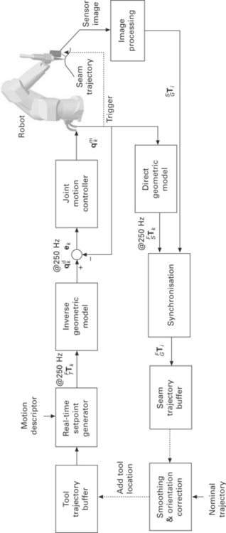
Figure 14.8 shows a block diagram of the trajectory-based control strategy.
The top part of this figure contains the robot trajectory generation, the bottom part contains the sensor integration part. The figure will be explained, starting from the top left.
The tool trajectory buffer contains a list of locations (positions and orientations) that the robot tool T (which can be S or L) has to pass through during the robot motion. These locations do not need to be equidistant. During the robot motion, new locations can be added to the tool trajectory buffer, thus extending the robot trajectory.
A real-time setpoint generator interpolates the locations in the tool trajectory buffer and computes location setpoints FTTk for every kth fixed time interval (4 ms in our case). The movement should be smooth as defined by the maximum acceleration, velocity and deceleration specified in the motion descriptor. A real-time setpoint generator that uses cubic interpolation based on quaternions is used (De Graaf, 2007).
From a location setpoint FTTk, the known tool transformation NTT and the known frame transformation BFT, transformation BNTk is calculated. Next, a robot joint angle setpoint qdk is calculated using the inverse geometric model (Khalil and Dombre, 2002).
The robot joint angle setpoints qdk are the reference input for the joint motion controller, which is proprietary to Stäubli. It tracks the joint measurements qmk in such a way that the tracking error |qdk− qmk| on the specified path remains small.
The seam-tracking sensor computes the transformation SGTi from a camera image using image-processing, where i is a measurement index. If properly synchronised, SGTi can be related to the measured joint angles qmk to compute a seam location FGTi. The result is stored in the seam trajectory buffer. After the robot joints and sensor image are synchronised, the actual time upon which the seam locations were measured is no longer relevant as the seam is defined by its geometric description only. Of course, the order in which the seam locations are obtained is of importance and it has to be assured that the number of points measured on the seam trajectory is sufficient in relation to the complexity of the seam. By moving the sensor tool along the seam trajectory and storing the seam locations obtained in the seam trajectory buffer, the complete geometry of the seam trajectory is obtained. For real-time seam tracking, the smoothing and orientation correction block is needed. In particular for this operation, the trajectory-based control approach yields some major advantages, compared to the common time-based control approaches:
• The measured locations in the seam trajectory buffer can be filtered in the position domain instead of in the time domain. This is more logical as seam trajectories are characterised by their radius of curvature. Curvature is meaningful in the position domain, not in the time or frequency domain.
• Both historical and future information is available for filtering as the sensor measures ahead of the laser focal point. Phase-coherent or central filtering can be easily applied.
• The sensor image processing is not part of the robot motion control loop. The control structure is therefore independent of a variable delay after processing of the sensor image, which may be caused by the image processing algorithm. Furthermore, stability issues are properly decoupled this way.
• It is easy to remove outliers. The sensor measurements may be incorrect (due to dust, spatter from the process, etc.) or completely missing (due to sensor-robot communication errors). As long as the robot tool frame has not reached the end of the tool trajectory buffer, the movement will continue.
The trajectory-based control structure only differs slightly for the mentioned seam teaching and seam tracking operations. In the case of teaching of a seam trajectory, with prior knowledge of its geometry, the smoothing and orientation correction block in Fig. 14.8 is not used, because the tool trajectory locations are known beforehand and the seam trajectory only needs to be recorded. For the other three procedures, the control loop has to be closed by on-line calculation and addition of locations to the tool trajectory buffer. A proper smoothing must be taken care of to prevent oscillatory motion behaviour, because the trajectory-based control strategy contains no other bandwidth limitations. In the case of teaching an unknown seam trajectory, the tool trajectory buffer needs to be filled with estimated seam locations, somewhere ahead of the current sensor location, which are extrapolated from the measured seam locations.
For real-time tracking of a seam trajectory, the sensor is used to obtain the location of the actual seam trajectory. The laser spot is kept on this seam trajectory. Obviously, the seam trajectory has to remain in the sensor's field of view, e.g. by rotating slightly around the laser tool. Real-time seam tracking without any prior knowledge of the geometry of the seam trajectory is considered to be impractical for safety reasons. We suggest that real-time seam tracking is only performed when a nominal seam trajectory is already present to prevent the welding head from hitting obstacles in the work cell due to erroneous sensor measurements, e.g. scratches. Only small deviations from a nominal trajectory are allowed. The nominal seam trajectory will be kept in the sensor's field of view to make sure its measurements can be used.
A detailed description of the trajectory-based control architecture is beyond the scope of this chapter. Experimental results and a description of the algorithms used can be found in De Graaf (2007).
14.7 Conclusion
To conclude this chapter, an overview is given of reasons that limit the current applicability of industrial robots for laser welding, which have been partly solved in this chapter:
• Serial link robots have a poor absolute accuracy at tip level, as the inaccuracies of each link accumulate towards the tip. The repeatability is usually an order higher. By making smart use of sensor information, the welding accuracy can reach the repeatability levels.
• The robot controller interface is not designed for the complex application of sensor-guided robotic laser welding. Many robot controllers allow operators or system integrators to program the robot controller with custom robot programming languages. These languages are usually fine for simple applications, like pick-and-place, but lack functionality for complex applications where modifications of the robot trajectory are needed on the fly. Furthermore, the programming languages differ between each robot manufacturer.
• Accurate synchronisation between the robot joint angles and external sensors is needed if tip-mounted sensors are used at high speeds. Most robot controllers have this information available at a low level, but few of them have a generic interface to synchronise with external sensors.
• Errors in the robot geometric model limit the accuracy of the tool calibration procedures, the seam teaching procedures and the real-time seam tracking procedures. It is expected that a considerable improvement can be achieved when more accurate geometric robot models are available, e.g. by calibrating the robot.
A number of promising techniques and trends are recognised to further improve the accuracy and usability of robotic laser welding:
• Development of integrated and compact welding heads (Iakovou, 2009; Falldorf Sensor, 2006): Welding heads with integrated sensors that measure close to or at the laser focal point give a great increase in welding accuracy. Besides this advantage, the welding head that is developed by Iakovou measures with a triangle around the laser focal point and does not require a specific orientation of the sensor relative to the seam trajectory. Therefore, it can be used to measure and weld specially shaped trajectories like rectangles, circles, spirals, etc.
• Iterative learning control (Hakvoort, 2009): ILC is a control strategy used to increase the tracking accuracy of the robot joint motion controller, by repeating the trajectory and learning from errors made in previous runs. For laser welding this has the advantage that the tracking accuracy of the laser spot is considerably increased (better than 0.05 mm), even during welding of complex trajectories, e.g. sharp corners. The accuracy increase comes at the expense of a decrease in cycle time, as the welding trajectory needs to be taught at least once before it can be welded. Furthermore, a welding head with an integrated sensor that measures close to or at the laser focal point is needed.
• Improved laser beam manipulation (Hardeman, 2008): In this work, laser welding scanning heads are considered, where the laser spot can be moved in one or more directions by means of a moving mirror. These scanning heads contain integrated seam-tracking sensors and a motorised mirror. Using an integrated feedback controller, the laser spot is kept on the seam trajectory.
• Off-line programming for laser welding (Waiboer, 2007): Off-line programming software can be used to generate welding trajectories for complex 3D products. In the software, 3D models of the welding cell, robot, external manipulator, welding head, worktable, product and clamping materials can be used to create a collision-free welding trajectory. A disadvantage of off-line programming software is the deviation between the product position in the software and in the real work cell. Off-line programming software is very useful to generate complex welding trajectories, without spending a lot of time and money on the real welding equipment. Next, the work from this thesis can be applied using sensors to teach the actual seam with the accuracy that is needed for laser welding.
• Synchronous external axes support: By positioning the product on an external manipulator that moves synchronously with the robot arm, fast robot arm movements can be decreased considerably for complex products by using a combined motion of the robot and product on the manipulator, thus decreasing the dynamic tracking errors. Furthermore, the external manipulator can decrease gravity effects during welding by keeping the melt pool horizontal. The combination of external axes and sensors for seam teaching and seam tracking is considered a challenge.
14.8 References
Andersen, H. J. Sensor Based Robotic Laser Welding – Based on Feed Forward and Gain Scheduling Algorithms, 2001. [PhD thesis, Aalborg University].
Chou, J. C. K., Kamel, M., Quaternions approach to solve the kinematic equation of rotation AaAx = AxAb of a sensor mounted robotic manipulator. Proceedings of the 1988 IEEE International Conference on Robotics and Automation. 1988:656–662. [Philadelphia].
Craig, J. J. Introduction to Robotics: Mechanics & Control. Reading, MA: Addison-Wesley; 1986.
Daniilidis, K. Hand-eye calibration using dual quaternions. The International Journal of Robotics Research. 1999; 18(3):286–298.
De Graaf, M. W. PhD thesisSensor-Guided Robotic Laser Welding. University of Twente, 2007.
De Graaf, M. W., Aarts, R. G. K. M., Meijer, J., Jonker, J. B. Robot-sensor synchronization for real-time seam tracking in robotic laser welding. Munich: In Proceedings of the Third International WLT-Conference on Lasers in Manufacturing; 2005.
Duley, W. Laser Welding. New York: Wiley Interscience; 1999.
Sensor GmbH, Falldorf. http://www. falldorfsensor. com, 2006
Fridenfalk, M., Bolmsjö, G. Design and validation of a universal 6D seam tracking system in robotic welding based on laser scanning. Industrial Robot: An International Journal. 2003; 30(5):437–448.
Hakvoort, W. B. J. PhD thesisIterative Learning Control for LTV systems with Applications to an Industrial Robot. University of Twente, 2009.
Hardeman, T. PhD thesisModelling and Identification of Industrial Robots including Drive and Joint Flexibilities. University of Twente, 2008.
Huissoon, J. P. Robotic laser welding: seam sensor and laser focal frame registration. Robotica. 2002; 20:261–268.
Iakovou, D. PhD thesisSensor Development and Integration for Robotized Laser Welding. University of Twente, 2009.
Kang, H. S., Suh, J., Cho, T. D. Robot based laser welding technology. Materials Science Forum. 2008; 580–582:565–568.
Khalil, W., Dombre, E. Modeling. Hermes Penton: Identification & Control of Robots, Stanmore, Middlesex; 2002.
Lee, S., Ro, S. A self-calibration model for hand-eye systems with motion estimation. Mathematical and Computer Modelling. 1996; 24(5/6):49–77.
Lu, C. P., Mjolsness, E., Hager, G. D. Online computation of exterior orientation with application to hand-eye calibration. Mathematical and Computer Modelling. 1996; 24(5/6):121–143.
Nayak, N., Ray, A. Intelligent Seam Tracking for Robotic Welding. Springer-Verlag: Advances in Industrial Control. Berlin; 1993.
Park, F. C., Martin, B. J., Robot sensor calibration: Solving AX equals XB on the Euclidian group. IEEE Transactions on Robotics and Automation. 1994:717–721.
Regaard, B., Kaierle, S., Poprawe, R., Seam-tracking for high precision laser welding applications – methods, restrictions and enhanced concepts, Journal of Laser Applications, 21(4). 2009.
Shiu, Y. C., Ahmad, S., Calibration of wrist-mounted robotic sensors by solving homongeneous transform equations of the form AX=XB. IEEE Transactions on Robotics and Automation. 1989:16–29.
Thorne, H. F. Tool center point calibration for spot welding guns, 1999. [US Patent US5910719,].
Tsai, R. Y., Lenz, R. K., A new technique for fully autonomous and efficient 3D robotics hand/eye calibration. IEEE Transactions on Robotics and Automation. 1989:345–357.
Van der Heijden, F. Image Based Measurement Systems: Object Recognition and Parameter Estimation. New York: John Wiley & Sons; 1994.
Van Tienhoven, J. Automatic Tool Centre Point Calibration for Robotised Laserwelding. Master's thesis: University of Twente; 2004.
Waiboer, R. R., Dynamic Modelling PhD thesisIdentification and Simulation of Industrial Robots – for Off-line Programming of Robotised Laser Welding. University of Twente – Netherlands Institute for Metals Research, 2007.
Zhuang, H., Shiu, Y. C. A noise-tolerant algorithm for robotic hand-eye calibration with or without orientation measurement. Man and Cybernetics: In IEEE Transactions on Systems; 1993. [pp. 1168–1175].

