Developments in disk laser welding
Abstract
The chapter presents different applications in welding with disk lasers. This includes the general concept of disk lasers and the advantages of disk laser welding in comparison to other laser concepts. Presented applications include laser welding of sheet metal, welding in precision machining, laser metal deposition, laser scanner welding and laser hybrid welding.
4.1 Introduction: key principles of disk lasers
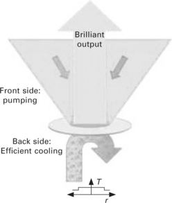
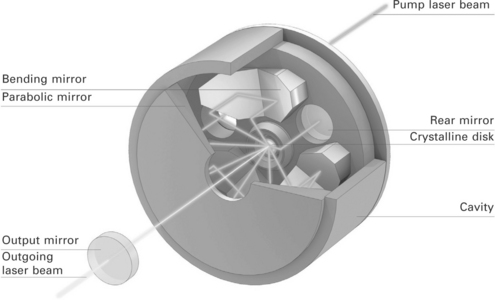
While the disk laser concept was invented in the early 1990s, the first industrial products were available in 2003. Before the disk laser was invented, the rod laser was dominating the solid-state laser market. But the relatively thick rod leads to a parabolic temperature profile (higher temperature in the inner part of the rod, lower temperature at the outer part) and limited the output power and beam quality respectively. The next step in laser development was a laser with a thin disk. The laser gain medium of such a laser is a wafer-thin crystalline disk made of Yb:YAG, about 15 mm in diameter and 0.2 mm thick. The disk rests on a heat sink, which dissipates heat and cools the disk, effectively eliminating the disadvantages of a rod and allowing highest output power at very good beam quality (see Fig. 4.1). The cooled rear side of the disk has a reflective surface, which reflects the laser beam and pump light and acts as a folding mirror. The disk laser is pumped by efficient diode lasers. Their pump laser beam is focused to a diameter of a few millimeters and then aimed at the disk. The disk is so thin that it absorbs only a fraction of the pump radiation that passes through. For this reason, the pump beam is passed through the disk several times, by means of a pair of folding mirrors and a parabolic mirror in the interior of the cavity (see Fig. 4.2).
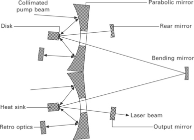
The laser beam is produced in the disk and exits the cavity through a hole in the center of the parabolic mirror. The output mirror of the resonator is located outside the cavity. The laser power can be modified in different ways: on the one hand via the excitation power, in other words the power of the pump laser beam; and on the other hand via the irradiated area of the disk. Laser power of up to several kilowatts can be generated with one cavity. For even greater power levels, up to four cavities can be optically coupled. Folding mirrors (also called bending mirrors) guide the laser beam from cavity to cavity, connecting the cavities optically (see Fig. 4.3). Here, too, the end mirror and output mirror of the resonator are located outside the cavities.
The disk laser design benefits from unique properties:
• Virtually no thermal lensing (flat temperature profile) due to axial heat flow enables high brightness of the disk laser.
• Low power densities on the active material because of large pumping diameters.
• Low brightness requirements of the pump diodes enable cost-effective lasers with high electrical to optical conversion efficiency – especially in the high average power regime.
• Area scaling of the beam cross section enables power scaling while keeping constant internal intensities.
• Deep gain saturation eliminates harmful back reflection problems.
• The modal cross sections are generally large compared with the longitudinal extension of the gain medium. Therefore high peak power sources are possible without facing problems due to nonlinearities.
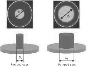
Figure 4.4 shows the option to adapt the pump spot on the disk, which is advantageous for the scalability of the output power per disk. The output power from a single disk can be increased while still keeping the pump power density constant. Only the pump spot diameter increases with the square root of the desired output power. If the pump spot diameter is doubled, one can increase the pump power by a factor of four without changing either the power density or the thermal conditions inside the disk. Contrary to other concepts, such as the rod or fiber laser, the power density on the disk itself is uncritical, even at the highest output power.
With this concept it was very easy to increase the output power of one disk without changing the beam quality. A change in beam quality has virtually no effect on the obtainable output power of the beam source. Therefore the beam quality of the disk laser can be adapted to the needs of the targeted applications.
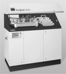
In addition, Fig. 4.5 shows an output power out of one disk of about 5.5 kW achieved for industrial environments. This is the basis of the TruDisk 4002, which guaranties 4 kW at workpiece. The reserves of the laser can be used to realize a power feedback control and to compensate power losses in optical components such as beam guidance, laser light cables and focusing optics. As the achieved welding depth is directly related to the laser power, the end user cannot accept any variation of this parameter. Unlike other laser concepts, neither the environmental conditions nor internal parameters (like cooling water temperature of the laser) have any influence on the output power, which remains constant at all times in the case of the TruDisk. As a result of the increased output power per disk, the number of components and therefore the size of the laser and the cost of the system were dramatically reduced.
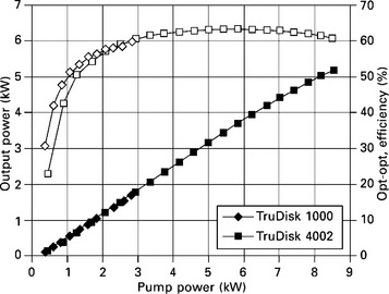
4.5 Output power and efficiency of a typical high power single disk laser oscillator for two beam qualities, BPP = 2 mm mrad (1 kW laser) and BPP = 8 mm mrad (4 kW laser).
Besides the high potential for CW lasers, the mentioned advantages of the disk laser concept lead to a new generation of lasers: short-pulsed lasers (ns pulse duration) and ultra-short-pulsed lasers (ps pulse duration). The disk as a regenerative amplifier is used to amplify low power pulses and hence to achieve pulses with highest peak power and high pulse energy (up to 50 MW peak power (ps pulses) and up to 150 mJ (ns pulses) demonstrated at TRUMPF). These lasers are mainly used in micro applications such as cutting of mobile display glass, various applications in the photovoltaic industry, drilling holes, e.g., in injector nozzles or scribing materials like ceramics.
4.2 Technological trends and developments
The first available disk lasers have been operated with approximately 500 W output power per disk. Improving the technology in different steps lead to 1 kW per disk, 2 kW per disk, 4 kW per disk and nowadays even to 6 kW per disk output power. The result was a price decline, a dramatic reduction in footprint and an increase in overall efficiencies of up to 30% which is equal to a reduction in electrical power consumption by a factor of ten compared to lamp pumped rod lasers. The highest CW power at almost diffraction limited beam quality was demonstrated by Boeing with 27 kW laser power. Combining these results with the results achieved in ultra-short pulsed ps laser development (50 MW, 300 μJ, > 100 W average power), one can imagine the immense potential of the disk laser setup for high power CW lasers as well as for high peak power short pulse lasers. As mentioned, the theoretical limit calculated by the University of Stuttgart indicates that 30 kW from one disk could be possible. Hence, the future development of disk lasers will continue in three main areas:
• increase the output power per disk to reduce investment, operating costs and footprint at very good beam qualities suited for cutting, welding and brazing
• increase the peak power or pulse energy respectively for short-pulsed and ultra-short pulsed lasers for micro applications
• convert the wavelength: the features of the disk laser (e.g., modularity) makes it quite simple to convert the infrared wavelength to green or ultraviolet.
In summary, the disk laser principle will continue to play a decisive role for macro and micro material processing due to its high average power, high peak power, possibility for frequency conversion, truly scalability at constant internal intensities and its economical benefits in high efficiency, in short an ideal and versatile platform for industrial material processing.
4.3 Applications
4.3.1 Laser technology as part of the e-mobility mega-trend
E-mobility has generated a lot of interest in recent times. A big challenge to bring this trend into reality lies in the battery technology. Lithium-ion batteries seem most promising. The production process of lithium-ion batteries is already well known from the mobile phone industry. For e-mobility battery manufacturers now have to adapt the manufacturing process to their specific needs and to an even higher output. Laser technology is a key element. Besides laser marking, laser welding is indispensable for battery cell manufacturing and packaging of these. Remote welding with high-brightness disk lasers allows for the highest productivity.
Motivation
In the development of low emission technology for electric cars such as hybrid, plug-in hybrid or battery vehicles, the battery is the key component. The most preferred battery concept is the lithium-ion battery. A high power density and a very good reload behavior make lithium-ion batteries very attractive in comparison to other battery types. Within the production process of the lithium-ion battery, there are many applications for laser technology, from welding of the housing via welding of contacts to marking of the final battery.
Industrial implementation
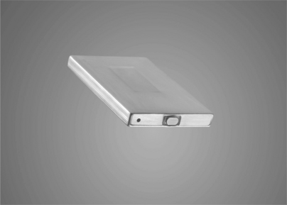
Lithium-ion batteries for mobile phones, hand-held devices and laptop computers are more compact than those for electrical vehicles but the manufacturing tasks are the same. A major task is the hermetic sealing of the aluminum housings. In the electronics industry, laser welding has been used for many years now to close the battery housings by welding a lid to the can. It is a state-of-the-art production technique and known as a well-established reliable manufacturing process. Other processes, such as micro plasma welding, do not meet the demands of the industry.
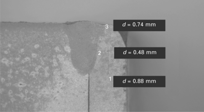
Pulsed Nd:YAG lasers have the biggest installed base in welding of lithium-ion battery housings. They create homogeneous, perfect and hermetically sealed weld seams without holes and cracks (see Fig. 4.6). A precise control of the laser power is needed in order to guarantee the quality of the seam. It also prevents damage to the inner parts of the battery by assuring a constant welding depth. Therefore, the pulsed Nd:YAG lasers TruPulse from TRUMPF have a real-time power control. Although the heat-input is low in laser welding, specially designed fixtures made of copper help to dissipate excess heat from the battery and to improve the weld seam quality as well.
With an average power of several hundred watts, welding speeds of a few meters per minute are possible with pulsed Nd:YAG lasers.
Lithium-ion battery manufacturers for electrical vehicles now make use of the broad experience of the electronics industry. Most manufacturers are evolving from electronics into the fast growing field of e-mobility, so they have the process knowledge already in-house. The key exercise for them is to increase the productivity and therewith lower the total costs for battery manufacture. The reason for that is the large number of single battery cells needed for one electrical vehicle to drive for several hours and several hundred kilometers. Millions of batteries per year are expected to be produced for electrical vehicles in the near future and the numbers will even grow.
One step here is to use continuous-wave solid-state lasers with an output power of 1–6 kW. High-brightness disk lasers of the TruDisk series are the ideal tool for welding of high-reflecting materials like aluminum and copper (Fig. 4.7). They are insensitive against back-reflections and allow higher welding speeds than pulsed Nd:YAG lasers. The welding speed of disk lasers of several meters per minute is a prerequisite to limit the heat input and the formation of spatters. Using a scanner focusing optics makes the process often more profitable, because it allows guiding the laser beam a lot faster.
In many installations image processing helps to optimize the welding process by exactly positioning the laser beam on the weld seam. It can compensate tolerances in the parts and fixture and additionally can be used for quality inspection, too, if needed. For traceability reasons, all batteries are marked with a serial number and often with even more production-relevant data. Marking lasers are ideally suited for this permanent mark. They can be integrated directly into the production line.
4.3.2 Laser welding in sheet metal
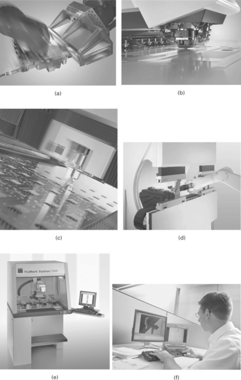
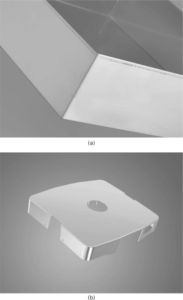
The joining process has always played a crucial role in sheet metal fabrication. Alongside component marking, it comes at the end of the sheet metal process chain and therefore has to meet particularly high demands in terms of delivering a high-quality weld seam with little need for post-weld work (see Fig. 4.8).
The current machines for laser cutting, punching and bending sheet metal parts are high-precision systems that produce metal components to tight tolerances. Up to now the subsequent joining process has largely consisted of arc welding, such as tungsten inert gas (TIG) or gas metal arc (GMA) welding. Despite new developments to reduce the heat input per unit length of weld – using low-energy arc welding techniques – considerable distortion is usually caused by the introduction of energy over a large area of the component by the arc. After the joining process, considerable straightening and other post-weld work has to be performed on the precision-manufactured part.
In this respect laser welding enjoys an immense advantage. The small melt pool and low amount of heat introduced significantly reduce the amount of weld distortion compared with conventional methods. Hardly any post-weld work is therefore necessary, and the seams possess very high static and dynamic strength. Narrow, precise, contact-free welded seams produce smooth, fault-free surfaces. The high process speed and reproducibility of laser welding reduce costs, while delivering higher quality. As sheet metal fabricators increasingly individualize their product portfolios, laser welding yields decisive competitive advantages: thanks to the advantages described, the investment in a laser welding system is recouped even from small batch sizes when all cost-relevant factors are considered.
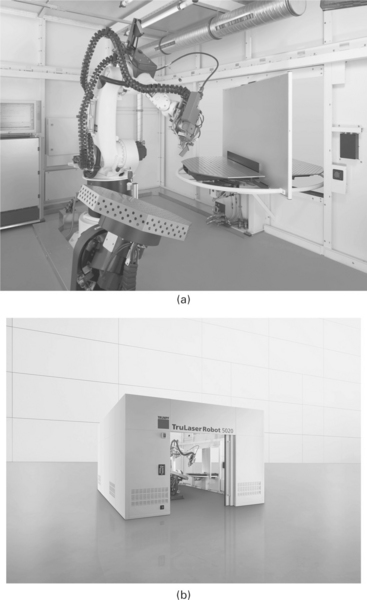
Robot-guided systems are particularly suitable for manipulating the laser welding beam. With their six axes, and possibly also additional positioning axes, they possess great flexibility and can perform complex movement sequences on frequently changing parts in response to standardized travel commands (see Fig. 4.9). Thanks to their great flexibility, fully automatic robot systems for laser welding are an ideal choice for an extremely wide range of applications. These extend from sheet metal users engaged in the manufacture of automotive parts and kitchens, to those involved in electrical and precision engineering, mechanical engineering and medical technology, through to tool and die making.
Possible applications in sheet metal fabrication are presented below, taking medical engineering components as an exemplary reference. Workpieces in this sector must meet the most exacting demands, because safety and hygiene have top priority in patient care. For example, robot laser welding systems have been used successfully for years to produce operating tables. Deep penetration welds are made on parts that have to meet high strength requirements, while heat conduction welds with a smooth and dense visible seam are also produced (see Fig. 4.10).
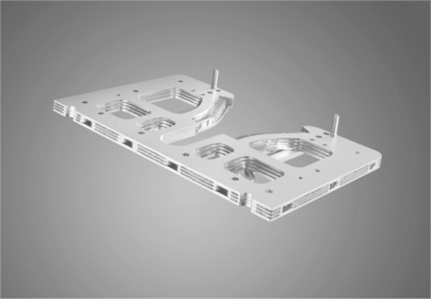
A further possible application of laser welding is the substitution of milled parts by laser-processed sheet metal components (see Fig. 4.11). The laser-cut sheet metal parts are positioned in sandwich configuration and then welded by the laser beam. The high travel speeds in laser cutting and welding, the low component distortion and the high strengths produce an efficient, low-cost component that possesses the same functionalities as a comparable milled part.
Laser welding with flexible robot systems has been established for years in many areas of industry. Ongoing optimization of the control technology has made it progressively easier to operate the robot systems, which has encouraged the more widespread industrial use of this technology. In addition, most robot installations today incorporate measuring systems which make them easier to use both in production planning as well as in the actual production process. As a result, robot laser welding systems can meet the major and diverse challenges that exist in sheet metal fabrication. This is true not only in respect of rising standards in component design, weld preparation and related process sensor technology, but also in the face of increased individualization, as batch sizes get smaller and change more frequently.
4.3.3 Laser metal deposition by powder injection
Laser metal deposition (LMD) is used to produce coatings with defined properties as well as to repair areas where material is missing due to wear or damage. This technology can also be applied to add material on the component surface in order to change the part design.
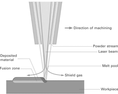
By means of this technique, a deposit material is melted by the laser heat source. Part of the energy is absorbed by the substrate causing controlled melting of a thin layer of the base material. This ensures a metallurgical bonding between the coating and the base material. The deposit material can be transferred to the substrate by powder injection or wire feeding. If using deposit materials in powder form, the powder particles are fed into the melt pool by appropriate delivery nozzles (see Fig. 4.12). Single layers with a coating thickness between ca. 0.3 mm and 2 mm can be produced. Several layers can be deposited one upon the other in order to increase the total coating thickness. Track widths as narrow as 0.4 mm can be obtained.
Examples of application of this technology include:
• repairing of injection molds in mold making and tool manufacturing.
• reconditioning of bearing seats (bearing contact surfaces), shafts, rods and seals, sliding valves and discs, exhaust valves in engines as well as cylinders and rolls in mechanical engineering applications.
• refurbishment of turbine and compressor blades, Z-notches, nozzle guide vanes (NGVs), sealing elements and casings in jet engines; also gas turbine blades can be repaired using this technique.
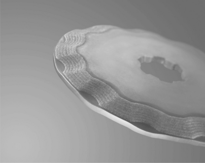
Since, by means of deposition, welding coatings with improved resistance against abrasive, erosive and adhesive wear can be produced, this technique is used for the coating of cutting tools (see Fig. 4.13).
Also a major application of laser metal deposition is the repair and refurbishment of high-value components such as piston ring grooves in modern four-stroke engines. The surfaces of the piston ring grooves are affected by chemical corrosion and wear due to hard particles in the fuel. For reparation by laser metal deposition, cobalt and iron-based alloys can be used (see Fig. 4.14). Deposit requirements are not only appropriate wear resistance but also resistance against oscillating temperature profiles.
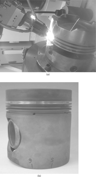
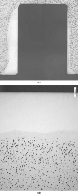
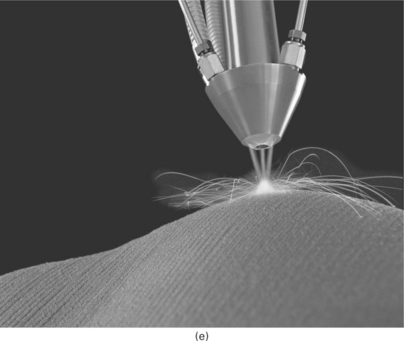
4.14 (a, b) Piston ring groove after laser metal deposition and machining, by courtesy of Gall & Seitz Systems GmbH (Hamburg, Germany). (c, d, e) Refurbishment of piston ring grooves by laser metal deposition.
The laser technologies offer many advantages when compared with conventional processes such as TIG deposition welding: the thermal load produced by the laser beam affects only the area immediately surrounding the weld itself, making it possible to reduce dilution, distortion and thermal stress formation. In addition to this, by means of the laser, it is possible to coat complex 3D structures and to access hard-to-reach areas like inside edges or sunken holes. Disk or direct diode lasers (e.g., TruDisk, TruDiode) are suitable for automated deposition welding, the relative movement between the substrate and the laser optic being provided, depending on the required working envelope and positioning accuracy, by robotic manipulators or Cartesian machines.
4.3.4 Laser scanner welding
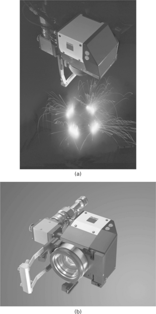
Remote laser welding or laser scanner welding is one of the most common and successful global applications of the disk laser. Many automotive companies as well as suppliers (e.g., seat industry) rely on the disk laser technology and have integrated remote welding in their production lines. The controllers of the TRUMPF programmable focusing optics (PFO) scanner systems can be linked together with the motion controllers of robotic systems in order to achieve full synchronization between the motion of the robot axes and the activity of the scanner optics. This so-called ‘welding-on-the-fly’ allows for the fastest material processing while the scanner optics is being moved in space by the robot which enlarges the scanner’s processing space and, in addition, which provides three-dimensional access to the processed part, if needed.
In this way it only takes a few seconds to weld components like car doors precisely and firmly. Doing this, the robot arm carries the scanner optics along a smooth path at a constant working distance of about half a meter over the workpiece. Deflection mirrors within the PFO direct the focal point in fractions of a second from weld seam to weld seam. A TruDisk disk laser far away from the processing station generates the laser beam. Up to 100 m long, flexible laser light cables conduct it to the programmable focusing optics. The PFO at the end of the laser light cable is the central element for the precise positioning of the laser’s focus point on the car body component. Inside the PFO, two very rapid and precisely pivotable deflection mirrors direct the beam through a so-called flat field objective. Thus, in fractions of a second they adjust the created focus point remotely in X and Y directions within the total work field, without any need to move the entire scanner optics itself. If in addition the PFO is also equipped with a moveable lens inside, this lens can also control the position of the focal point along the Z axis (Figs 4.15 and 4.16). The repositioning of the focused laser beam from one end to the other of one of these three positioning axes takes a mere 30 ms.
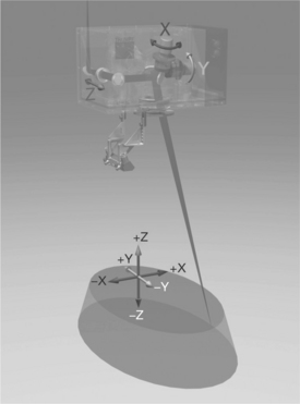
4.15 Principle of the programmable focusing optics (PFO) 3D. Two rotatable mirrors are positioning the beam in the X and Y directions. The movement of an additional lens is positioning the focus location in the Z direction.
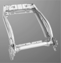
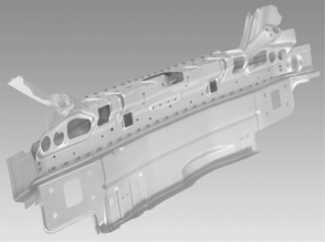
There are three basic preconditions for welding on the fly: first, a solid-state laser is needed as the beam source. Only flexible fiber optic cables that can follow the movement of the robot can conduct the laser beam to the scanner optics. The second precondition is high laser beam quality so that in spite of the long focal length of the used flat field objective, it is still possible to create a sufficiently small focus point. This is necessary because for the intended deep penetration welding process, the diameter of the focal point should not exceed 0.6 mm. Modern diode-pumped solid-state lasers like the disk laser generate the usual laser output powers for remote laser welding in car body production of 4–6 kW with beam qualities of 4–8 mm mrad. This allows for focusing distances three to six times the focusing distance being possible with a lamp pumped laser at the same laser power level. The third condition for the positioning of weld seams on the component exactly to the millimetre is the online synchronization between the robot and the scanner control. The scanner control can only take into account possible deviations of the robot from the originally programmed pathway, and compensate for them at any time of the on-the-fly laser welding process, if the robot control communicates to it the actual position of the scanner optics over the component in real time. The biggest advantage of the remote welding process is the extremely high productivity. Inefficient and unproductive times between welding steps can essentially be eliminated. Therefore, the laser, as a welding tool, can be used in the most efficient way possible. While the laser-on time of conventional laser welding applications is about 30–40%, the remote laser process enables laser-on times of up to 90%. In comparison to conventional resistant spot welding, the process speed can be increased by a factor of three to ten! Another advantage of laser remote welding is a high flexibility. The geometry of the seam can be adapted to the actual stresses at the weld joint, which enables a continuously optimized laser suitable design. In addition, the seam geometry can be adapted to the local situation. While a slim flange leads to slim C-shape or linear welding geometries, circular C-shapes can be chosen, if the space enables such geometries. Figures 4.17 and 4.18 show a selection of different remote welding applications.
Welding patterns in any selected shape and size can be achieved with a PFO by means of the freely programmable built-in deflection mirrors with maximal welding speed and without any loss of precision, even when it is guided over the car body component by the rather clumsy and imprecise robot. The principal patterns used here are short lines, circles, C-shaped brackets or S-shaped welds. The free configuration, arrangement and orientation of the laser weld seams permit optimal adaptation of a welded joint to the subsequent load in daily use. In addition, linear laser weld seams require less space on the component than the circular weld spots produced with the resistance spot welding process. As a result, the width of the flange can be reduced. Smaller, lighter, and more economical components can be produced in this way.
The advantages are not only quantitative; there are also advantages in quality of parts because remote laser welding decreases production tolerances. On the one hand, it subjects the parts to less heat input and mechanical stress than the usual welding processes. The parts are not distorted as much and their structural geometry is not affected. On the other hand, the lower number of positioning and clamping procedures contributes to an even greater dimensional stability of the welded components as well as the entire car body.
4.3.5 Laser application in powertrain production
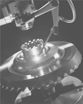
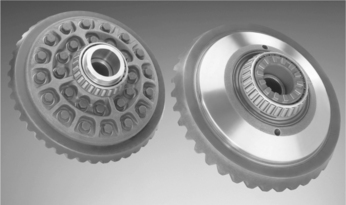
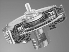
‘Powertrain parts’ refers to the group of components that generate power and deliver it to the road surface, water, or air (e.g. crankshaft, clutches, torque converters, gear parts, drive shafts, wheels, etc.) (Fig. 4.19).
Powertrain components and laser welding as a joining method found each other early on and they are a good match. The powertrain components have small tolerances and are mainly machined. During assembly, the parts are often additionally joined mechanically, i.e. they are attached, pressed in or shrunk. Ideally, in laser welding, this results in a joint gap that is very narrow or practically nonexistent. The laser seams, in turn, can bear heavy loads. The welding depth can be controlled more uniformly and precisely than with other welding processes. This contributes to high strength and quality of the welded components. The laser beam welds with very little or almost no distortion and the seam has a high finish quality. This frequently makes it possible to skip the refinishing step. Precision in laser welding also makes it possible to further reduce the tolerances in the transmission parts. The results are more durable transmissions that run quieter and are more comfortable for the driver and passengers. However, two additional factors are driving the current wave of investment in powertrain applications. There is political pressure to manufacture lighter-weight cars and, to help achieve that goal, find unused potentials in the powertrain and create processes to leverage them. For the example of a dual clutch, laser welding in production already achieves direct savings in terms of material and process steps. In addition, it can be automated and is suitable for manufacturing large production volumes (Figs 4.20 and 4.21).
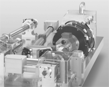
In addition to the classic CO2 lasers, solid-state lasers are also being used more often. The deep, subtle, highly stressed seams of many powertrain applications require a weld quality that for a long time primarily only CO2 lasers were able to deliver. But now even the current disk lasers meet the high requirements and offer the additional advantage that their light can be distributed by means of a laser network and fast changing beam switches on the processing stations. Additionally, solid-state lasers can be smoothly integrated into the production line since laser light can be easily delivered to the work station via fiber optic cable. The length of this fiber optic cable and thus the distance between the beam generator and the welding machine can be up to 100 m (Figs 4.22 and 4.23).
All processing steps can be monitored and controlled using modern sensor and camera technology. This is especially true for process-critical positioning and the welding process itself. In order to achieve a perfect seam, the joining partners must be perfectly aligned and the center of the focus spot – measured to only a few tenths – aimed precisely at the center of the joint gap. CCD Charge-coupled device (CCD) camera systems have proven reliable for this purpose, in that CCD systems are also able to identify different joining configurations or record and measure workpiece edges, openings and gaps and even an offset in the Z axis. If the components are suitably prepared, even a through-weld, for example in an annular duct, can be identified. The image processing system first gives the exact coordinates for positioning and determines, via a camera, whether the joint gap is optimal for welding. If errors are found, such as a joint gap that is too large, the control system reports this to the overriding controller and discharges the component as defective. The component can then be refinished and fed back into the process, which, in turn, reduces defects and makes the overall process more economical (Figs 4.24 and 4.25).
4.3.6 Hybrid laser welding with high laser power
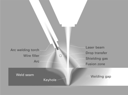
Laser hybrid welding emerged in the 1980s, as CO2 lasers were reaching the necessary performance yield for deep welding, often called keyhole welding. In this process, the laser beam partially vaporizes the work material. In this way, a deep, narrow vapor capillary is formed in the fused metal around the beam. This effect is both the strength and the weakness of the process. On the one hand, even very thick sheets can be welded in one pass over the entire face, something that is generally economically or technically not feasible with other processes. On the other hand, the beam requires a sophisticated focus in order to achieve the necessary power density. This means that the joining gap has to be so precisely prepared and the components so exactly clamped that the tolerances of the faces on the entire workpiece length measure in the tenths of a millimeter range. This is only worthwhile when the components are handy to work with and the sheets are thin or if the work or equipment required are justified by an increase in productivity or demands that will be made on the final product. To overcome these limitations, the idea arose that an electrical arc could be combined with the laser beam, because the metal gas welding melts more material into the surface, applies filler materials to the seam and can therefore better fill in the gaps. However, the weld penetration depth is comparatively small. If the sheets become thicker, nothing is left to do for weld preparation other than milling the offsets in a V shape and closing the ‘valley’ that develops with numerous welding beads in multiple layers. But arc welding introduces a large amount of energy into the workpieces, even when there are not many layers and on cooling, the beads shrink, which leads to deformations and internal stresses. And then there are the costs for fabrication time and additional materials.
Laser hybrid welding solves these problems. While the arc improves the filling in of the gap, the laser increases the weld depth and the welding speed, thus considerably reducing the heat input. In spite of larger tolerances, the seam can be made in a single pass. In addition, with a higher processing speed, the melted welding volume is considerably lower so that much less heat is applied to the surrounding material (Fig. 4.26).
The breakthrough finally came with high-performance solid-state lasers. And yet there was a catch that delayed the spread of the process. The arc requires the plasma to do its work. However, this is a hindrance for the CO2 laser because the plasma absorbs its beams. Added to that is the fact that the CO2 laser itself produces plasma; it ionizes the metal steam cloud from the keyhole. When welding with CO2 lasers, this plasma is ‘thinned down’ with gases such as helium that are hard to ionize. One non-ionizable helium cloud, however, is the last thing a MAG weld burner needs between the electrode and the workpiece. In addition, the CO2 laser cannot be transmitted in a laser light cable, which makes the processing of three-dimensional parts more difficult. But this is important, because laser hybrid welding is generally applied to components with unusual dimensions. That is why the traverse paths are large and controlling the beam in the optical path becomes a challenge.
All of that changed when the disk laser broke through into the high performance range. The light from the solid-state lasers ionizes the metal vapor cloud very little or not at all. It is not absorbed by the plasma, anyway, so the arc plasma is no longer a problem. Moreover, with laser light cables it can be deployed to many processing stations. As a result, the distance from the processing head to the beam source or travel paths no longer makes a difference.
Figure 4.27 shows a cross section of a hybrid weld of 12 mm thick ship panels. The T-joint was done in one pass. The welding speed was 1.3 m/ min at a laser power of 8 kW. The left-hand side of the picture shows the advantage of energy sharing the laser beam, which has been used for years with the disk laser. A simultaneous weld from both sides (using an energy shared laser beam) decreases distortion of the welded part. Another big advantage of the laser hybrid welding is the additional heated material of the arc welding which leads to a smoother cooling of the laser weld seam and helps in total to reduce negative effects like cracks and low hardness.
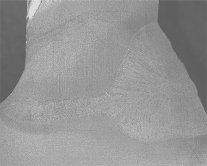
4.27 left: Laser hybrid welded T-joint; 8 kW laser power, welding depth 12 mm, welding speed 1.3 m/min right: double sided simultaneous welding of an 8 mm thick sheet (enabled due to energy sharing option of the disk laser).
Nowadays 10–15 mm thick plates in a single pass have been economically realized in industrial production. The limits for industrial production are more metallurgical effects like weld defects, cracks, dropping, hardness, etc., than the availability of the adapted laser system or laser power, respectively.
But the laser hybrid welding has already proven its high potential and hence there are different applications which will lead to future growth in different industries:
In summary, the laser hybrid welding process offers a lot of advantages, like increased welding speed with high sheet thicknesses. On the one hand, process efficiency is increased; on the other, the process enables less heat input into the material. Therefore, thermal distortion can be minimized. In addition, the combination of laser and arc increases the size of the fit-up gap that can be bridged compared to welding with the laser beam only.
4.4 Future trends
TRUMPF has further developed its disk laser technology. In 2009 a new series of industrial TruDisk lasers was released, which is the third generation of TRUMPF disk lasers. Compared to the second generation of disk lasers, significant reduction in both investment and running cost is achieved. The actual TruDisk generation is more cost efficient than ever before. The footprint of a 4 kW laser was reduced by 60% without cutting any of the well-known functionalities of the former TruDisk generation. Due to the versatile concept of the disk, both the output power as well as the beam quality can be adapted to the needs of all applications. While the maximum output power is increased to 16 kW, a beam quality of 2–8 mm mrad is available.
The new generation of disk lasers has set new standards for industrial laser sources regarding price, running cost and reliability. Although the uptime availability of disk lasers is known to be > 99.5%, the modular design allows a service and maintenance friendly system. Most of components can be exchanged by the user, without requiring a TRUMPF service technician.
The wide variety of different disk laser applications reflect the versatility of this laser concept. Applications in the micro area are served as well as in the thick sheet area. With the new ‘Cut assist’ option, the TruDisk possesses a superior intelligence which enables faster cutting on the one hand, as well as better cutting quality on the other.
Due to the excellent beam quality, the new TruDisk series is suitable for cutting and welding applications in the sheet thickness range of 0.05 mm to > 15 mm. Remote processes belong to the most common processes of the TruDisk laser. The disk laser has been used for remote welding for years with several worldwide manufacturing automotive OEM companies and suppliers. The latest development with the multi-kW TruDisk lasers was the melt pressure induced remote cutting, which can be used with sheet thicknesses of up to 4 mm.
Further development of disk lasers aims mainly to:
• increase the output power per disk
• reduce the investment and operating costs
• make the laser even more compact
• convert the wavelength: disk lasers combine high efficiency, excellent beam quality, high average and/or peak power with moderate cost and high reliability at multiple wavelengths, ranging from the infrared over the green to the ultraviolet; therefore, they are the ideal platform for wavelength conversion in short-pulse lasers (e.g., for the processing of silicon) and on the other hand for CW lasers (advantages in the processing of copper).
4.5 Sources of further information and advice
Avizonis, P., Bossert, D., Curtin, M., Killi, A., Schmitz, C., Physics of high performance Yb:YAG thin disk lasers. Conference on Lasers and Electro-Optics CLEO 2009, Baltimore, MD. 31 May 2009.
Bach, F. W., Möhwald, K., Laarmann, A., Wenz, T., Moderne Beschichtungsverfahren. Weinheim: Wiley–VCH Verlag. 2005.
Bernhardt, R., Schubert, H., Laser welding applications in the new Mercedes-Benz C-class. 8th European Conference and Exhibition, European Automotive Laser Application, Frankfurt. 30–31 January 2007.
Brockmann, R., Mann, K. Optimierte Fertigungstechnologie bei Audi: Laserscannerschweißen an den Türen des neuen Audi A4. Laser Technik Journal. 2007; 4(2):27–28.
Contag, K., Karszewski, M., Stewen, C., Giesen, A., Hügel, H. Theoretical modelling and experimental investigations of diode-pumped thin-disk Yb:YAG laser. Quantum Electron. 1999; 29:697–703.
Gasser, A., Neue Entwicklungen im Laserauftragschweißen für industrielle Fertigungsverfahren. Tagungsband des International Laser Technology Congress AKL’08, 2008.
Gasser, A., Meiners, W., Weisheit, A., Willenborg, W., Stollenwerk, J., Wissenbach, K. Maßgeschneiderte Oberflächen und Bauteile. Laser Technik Journal. 2010; 7(4):47–53.
Giesen, A., Der Scheibenlaser – Potential und Perspektiven. Presentation at In-house ‘Technologietag Scheibe’. Trumpf Laser Schramberg, 26 April 2006.
Giesen, A., Speiser, J. Fifteen years of work on thin-disk lasers: Results and scaling laws. IEEE Journ. of Sel. Topics in Quantum Electron. 2007; 13:598–609.
Giesen, A., Huegel, H., Voss, A., Wittig, K., Brauch, U., Opower, H. Scalable concept for diode-pumped high-power solid-state lasers. Appl. Phys. B. 1994; 58:365–372.
Herwig, P. Faserlaser zuverlässig vor Rückreflexen geschützt. Photonic. (5):2007.
Jasnau, U., Hoffmann, J., Seyffarth, P. Nd: YAG-Laser-MSG-Hybridschweißen von Aluminiumlegierungen im Schiffbau [Nd:YAG laser-GMAW hybrid welding of aluminium alloys in shipbuilding]. DVS-Berichte. 225, 2003.
Kelbassa, I. Qualifizieren des Laserstrahl-Auftragschweißens von Blisks aus Nickel- und Titanbasislegierungen. Dissertation. RWTH Aachen, 2006.
Klemm, P. : Softwaretechnik für Prozessplanung und Leitsysteme. Lecture notes, Universität Stuttgart.
Miebach, R., Lembeck, H. Die neue Fertigung der Meyer-Werft: Laserhybridschweißen als Kerntechnologie [The new manufacturing process at the Meyer Werft shipyard: laser hybrid welding as key technology]. DVS-Berichte. 2003; 225:187–192.
Ohnesorge, A. Bestimmung des Aufmischungsgrades beim Laser-Pulver-Auftragschweißen mittels laserinduzierter Plasmaspektroskopie (LIPS). Dissertation, Technische Universität Dresden; 2008.
Peters, M. Titan in Aufwind. MB-Revue. 2009; 72–77.
Roland, F., Pethan, G. Increasing efficiency and quality in shipbuilding and shiprepair by developing mobile laser equipment for the dock area. 4. Wismarer Fachtagung ‘Maritime Technik’. 2004.
Seyffarth, P. Erfahrungen des Werftausrüsters IMG bei der Einsatzvorbereitung von Lasertechnologien für den Schiffbau [Experiences of shipyard supplier IMG in preparing laser technologies for shipyard applications]. Bremen: 5th Laser Users Forum, 2006.
Staufer, H., Reinthaler, G., Ennsbrunner, H. : Operation and visualisation of the LaserHybrid Twin welding process. Doc. 212–1174-10, XII-2003-10.
Wagner, F. Laser-Pulver-Auftragschweißen zur Rekonditionierung von Schiffsmaschinenbauteilen. Dresden: Thermisches Beschichten mit laserbasierten Fertigungsverfahren, 2009.

