Developments in hybridisation and combined laser beam welding technologies
Abstract:
The laser welding process is the most flexible fusion welding process industrially available. The degree of flexibility is further enhanced and process limits are expanded if hybridisation or combination techniques are applied. After a general introduction of various related concepts, the enhancement of welding capabilities is illustrated in more detail by the state-of-the-art and latest advancements in laser-MAG (metal active gas) hybrid welding of up to 25 mm thick high-strength steel components. In addition, the manufacturing benefits of integrated cutting and welding with a multifunctional laser combi-head are described.
18.1 Introduction
Within the last three decades industrial lasers have become established as the tools for flexible manufacturing. Recent developments in fibre and disk lasers with multi-kW output power at beam qualities with single-digit mm*mrad values push the trend to laser assisted production even further. They open up new vistas to fibre-coupled laser systems, with multiple manufacturing cells sharing a single laser source. The increased electrical to optical conversion efficiency of the new diode-pumped sources and their better utilisation by laser networks leads to highly productive, flexible, and cost-efficient production solutions.
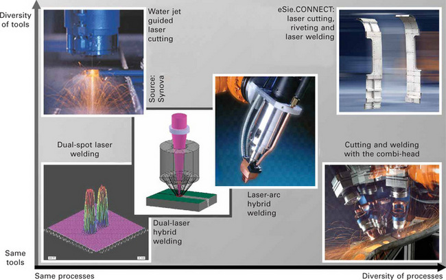
A further chance to enhance the capabilities of lasers is offered by their combination with other processes or tools. In fact, this idea is not new and already well implemented in various industrial applications. In order to systematise and illustrate the high variety of possibilities, Plate XXIII(between pages 328 and 329) presents a map of combined laser processes and tools. While the abscissa accounts for the diversity of involved processes, the ordinate displays the diversity of involved tools. The combination is specified as hybridisation if the combined tools are different and the processes are acting simultaneously in a common processing zone. Obviously this specification and the scales of the coordinates in Plate XXIII are rather qualitative. However, the distribution of the depicted examples in the map demonstrates their relative position in the context of the selected systematisation.
Let us start at the origin, which is at the left bottom corner of the map in Plate XXIII. It represents the area with the lowest diversity of the contributing tools and processes. The picture shows two laterally displaced laser foci – normally produced by a beam-splitting element in the focusing head. It is a well known method to improve the capabilities of laser welding aluminium [1] or overlapped zinc-coated steel sheets [2]. The two laser spots may be identical or slightly different in power or power density. In the latter case, the more powerful spot is arranged as the leading part of the dual-spot tool, which is responsible for promoting the welding process at the keyhole front. The trailing spot supports the action of the first one by increasing the welding depth and, more importantly, it prevents the capillary back wall from approaching the front wall and thus from choking the capillary. The capillary is elongated in the welding direction and the top and bottom capillary apertures are increased. The proper shaping of the capillary stabilises the welding process and facilitates the escape of gas (such as insoluble hydrogen in aluminium) and vapour (such as vaporised zinc of coated steel sheets). Thereby, porosity and melt expulsions are significantly reduced. Another well-established application for the ‘dual-spot laser welding’ technique is using the two spots displaced transversally to the weld track, in order to increase the bridging capabilities (e.g. during welding of tailored blanks). Already this simple example at the origin of the map illustrates the benefits which can be achieved by changing from a standard system configuration to a combination of, in this case, even identical laser tools supporting the same process.
Consistently following this idea, we move only a little diagonally on the map, and arrive at the combination of different laser distributions, originating from the same or different lasers. The ‘dual-laser hybrid processing’ can be used, for example, by combining standard laser beams with diode laser beams, arranged in advance, subsequently or coaxially. Examples of this approach are the overlap welding of zinc-coated steels [3] and the burn-off stabilised thick section cutting of steel plates [4]. The assisting diode laser radiation provides additional heat beside the actually processing laser beam. The induced lateral temperature field serves, for example, for preheating, decoating, premelting or post-processing.
In the centre of the map, ‘laser-arc hybrid welding’ represents one of the most established laser hybrid processes. It will be discussed in more detail below, as well as ‘cutting and welding with the combi-head’, using a single tool for processes as different as cutting and welding, thus being well located in the bottom right corner of the map in Plate XXIII (between pages 328 and 329).
Exactly at the opposite corner of the map, the ‘water jet guided laser cutting’ is an impressive example of how a sophisticated combination of laser radiation with a completely different tool can expand the application range of lasers, both figuratively and literally speaking. A pressurised water jet with a diameter of 100 μm or less is used as a liquid laser waveguide into the cutting zone with a range of up to 100 mm. Additionally, the water jet supports material ejection out of the cutting kerf. The so-called micro-jet technique achieves an unrivalled focal position tolerance, effective cooling of the cutting zone and safe protection of the material surface from debris by the formation of a self-contained water film [5]. It is a laser hybrid process par excellence.
A special sequence of three different processes, the so-called ‘eSIE. CONNECT laser cutting, riveting and laser welding’ is positioned at the largest distance from the map’s origin in Plate XXIII. Here, a rather large diversity of processes and tools is combined in a process chain for the manufacturing of modular railway vehicles. Laser cutting is used for preparing the parts including the drill holes for the riveting process, riveting itself is used for pre-assembling the sheet metal structures without the requirement of expensive clamping devices, and laser welding is used as the final joining technique to accomplish the strength and endurance which are essential for railway vehicles [6].
The above described spectrum of combinations, some of them also representing hybridisations, illustrates the wide variety already existing in the laser field and demonstrates the potential for more in the future. The following sections deal with the principles, state-of-the-art and recent progress in two of the most important representatives of hybridisation and combination techniques, namely laser-arc hybrid welding and combined laser cutting and laser welding.
18.2 Laser and arc hybrid welding
18.2.1 Principles and state-of-the-art
The expression ‘laser-arc hybrid welding’ represents welding processes which use – besides the laser beam – an arc as the second source, acting in the same melt pool as the laser beam. The arc provides additional heat and, as the case may be, also filler material. Laser-arc hybrid welding processes are meanwhile the most established hybrid welding variants and well recognised for their robustness, efficiency and flexibility. Especially the coupling of a deep-penetrating laser beam with the heat and molten metal supplying gas metal arc (GMA) is a proven hybrid technique. It significantly expands the original welding application range of lasers.
Laser-arc hybrid welding has been investigated since 1978, when Professor Steen and co-workers in the UK published their first paper about TIG (tungsten inert gas) augmented laser welding [7]. Replacing the tungsten electrode by a wire-fed electrode, heat of the arc as well as molten filler material of the wire are transferred to the welding zone by the so-called MIG/MAG (metal inert/active gas) process. Since the first industrial laser-MIG hybrid system was put into operation by Fraunhofer ILT in the year 2000 at a German oil tank manufacturer [8], a hybrid boom can be observed and various new installations followed. Laser hybrid welding systems have been installed in shipbuilding [9,10], as well as in the automotive industry [11].
The laser-arc hybrid process is characterised by the simultaneous application of a focused laser beam and an arc, creating and moving a common melt pool along the weld pass (see Fig. 18.1). The combination offers an increased number of parameters compared to the single processes, thus allowing flexible control of the welding process adapted to the demands of material, construction and manufacturing conditions.
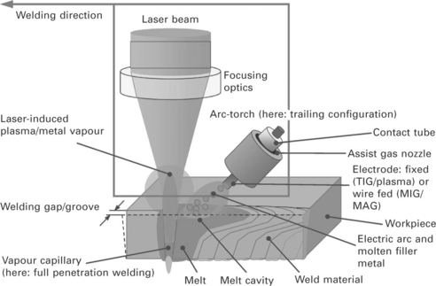
18.1 Principle of laser-arc hybrid welding [8].
The main benefits of the hybrid technique compared to laser beam welding with or without filler wire are:
• better gap bridging capability at lower laser beam power
• better levelling of edge offset
There are also significant benefits compared to arc welding techniques:
• weldability of zero-gap and I-seam at lap joint
• single-pass full-penetration welding even at high welding depth
• at T-joints or in corners: smaller fillet, more clearance.
The result is a more flexible and robust welding process providing higher productivity and quality.
The arrangement of the arc relative to the laser beam axis (leading, trailing or coaxial type, inclination and distance between laser and arc) depends on the material to be welded and its surface properties. Also important are type of joint, edge preparation and welding position. The laser and arc power, the laser focusing parameters, and the laser wavelength, as well as the striven metal-transfer mode (MIG/MAG) and special boundary conditions (e.g. the accessibility for a seam-tracking sensor) are other factors with strong influence on the design of hybrid process and equipment.
Normally, the smallest possible arc inclination is desired. Angles in the range of 15–30° relative to the laser axis work with technically acceptable effort. Nd:YAG, disk and fibre laser radiation, due to a lower interaction with the arc’s plasma, allows a closer approach to the arc than CO2 laser radiation, as long as the laser induced vapour jet is not leading to detrimental interaction effects.
The currently most preferred laser-arc hybrid welding process is using MIG/MAG. The process can be controlled in such a way that the MIG/ MAG part provides the appropriate amount of molten filler material to bridge the gap or fill the groove, while the laser is generating a vapour capillary within the molten pool to ensure the desired welding depth at high speed. The coupled process increases the welding speed above the sum of the single speeds, and produces an increased regularity of the weld bead. Improvements of metallurgical properties regarding hardness and toughness as well as diminished porosity due to promoted escaping of gas out of the enlarged melt pool are noted [8,12].
The correct setting of gas parameters is an important factor in hybrid welding, where laser and arc-specific criteria have to be taken into account simultaneously. Using Nd:YAG, disk or fibre laser radiation, beam absorption within the plasma and resulting plasma shielding can be neglected due to the shorter wavelength compared to CO2 lasers. Thus, with these lasers the selection of process gas can be determined according to the arc stability demands and bead shielding properties, for MIG/MAG also droplet detachment and spatter-free metal-transfer have to be considered. In this case argon will be the dominant portion of the gas used. Small addition of oxygen promotes the droplet detachment and reduces spatter. Mixtures of helium lead to higher arc voltage and the corresponding power increase results in wider seams, but also to a destabilising of the arc. Nevertheless, using CO2 lasers, a helium mixture is necessary to avoid plasma shielding. Fortunately, the presence of the laser beam enables acceptable arc stability even with a significant helium portion [8].
To demonstrate the general capabilities of laser-MIG/MAG hybrid welding, typical macro sections of seams in aluminium and steel are shown in Fig. 18.2 [12]. The examples provide evidence of fast speed, wide gap bridging, smooth levelling of misalignment and high quality. A further two examples in aluminium illustrate important hybrid welding features in more detail. In Fig. 18.3 the gap variation at butt joint in 4 mm aluminium sheets could be bridged even without any backing melt support or root protection [8]. Fillet welds at lap joint (see Fig. 18.4) get an effective reinforcement by the contribution of the MIG process [12].
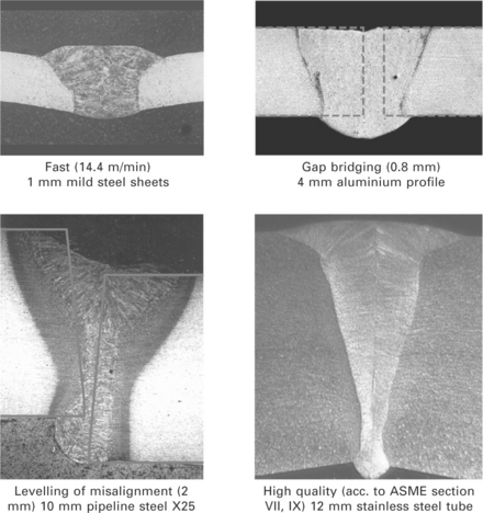
Fig 18.2 Cross sections and related parameters showing benefits of hybrid welding [12].
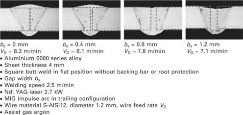
Fig 18.3 Gap bridging capability in an aluminium alloy [8].
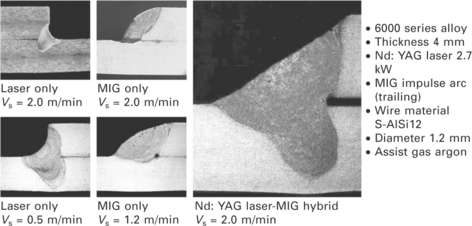
Fig 18.4 Hybrid welding of fillet weld at lap joint and comparison with the welding result using the single processes alone [12].
18.2.2 Physical model of the root formation
The appropriate amount of filler wire deposition depends on groove and gap volume as well as on welding speed and can easily be estimated and adjusted. The amount and the distribution of the energy input due to the laser beam power and the focal position influence the root formation and is handled experimentally. A remaining important question is: Which gap width can maximally be bridged and what are the determining factors for existing limits especially in thick-section welding?
As mass and energy balance have already been treated above, a momentum or pressure balance, respectively, shall give the answer (see Fig. 18.5). The pressure balance determines, for example, whether the root becomes concave with perhaps even incomplete penetration, whether it becomes convex and sound with regular appearance, or whether excessive penetration with drop through and sagging melt occurs. With a simple physical model the pressure balance at the root can be calculated [13]. The outcome will reveal suitable measures to improve gap bridging capabilities.
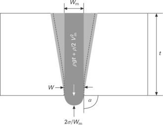
Fig 18.5 The pressure balance at the root [13].
The model illustrated in Fig. 18.5 considers the gravitational force (gravitational constant g) due to the mass of the melt column (density ρ and height t) above the root with width wm, the dynamic pressure of a ‘downward’ melt flow component with a velocity vm and the supporting capillary forces due to the surface tension σ of the root melt. The arc pressure could also be included in the balance equation, but during thick-section welding of steels its contribution can be neglected compared to the other terms. The gap width w determines the minimum possible root width. On the other hand, the root width determines the minimum possible root radius wm/2, which occurs at a contact angle α = 90° (see Fig. 18.5).
By setting gap and root width identical, the balance equation can be resolved for the maximum gap width wmax [13]:
To adjust the process, first of all an appropriate wire feed rate has to be set for properly filling the missing volume. It is also clear, that in order to fulfil the above condition of minimising the root width wm to the gap width w, the laser beam power has to be adapted, namely minimised, accordingly:
This is of course a somewhat idealised condition, but as the absolutely limiting case it perfectly leads to the maximum allowable gap.
Equation 18.1 presents three possibilities to maximise the allowable gap width wmax, which can be implemented by corresponding measures:
• increasing surface tension σ by root protection with inert gas (if two-sided access is accepted)
• reducing downward melt velocity vm by ensuring a stable process with low melt dynamics, mainly achieved by a proper basic parameter configuration
• avoiding gravitational effects by using horizontal position PC.
An example is calculated in Table 18.1, where three different theoretical cases for laser-arc hybrid butt welding of structural steel plates at a thickness of 15 mm in flat position PA are compared. A corresponding experimental value for the maximum allowable gap size with properly adapted wire feed rate and laser power has also been determined. The first case in Table 18.1 implies a clean root, free of oxides and with correspondingly high surface tension. Furthermore, an ideal situation with no downward melt flow is assumed. In the second case, an oxidised steel melt surface reduces the surface tension at the root, and in the third case additionally a significant melt flow velocity typical for high dynamics is indicated. Following these steps, the maximum gap width which can be bridged is decreasing from 1.7 mm to 0.5 mm. An experimental value of 0.7 mm has been achieved without root protection, which means with an oxidised root. The process was adjusted quite stable, which should result in a moderate downward melt velocity component. This condition meets the situation between the second and third case and corresponds very well with the average of these two theoretical values. This rather simple model provides a surprisingly accurate description of the gap bridging capability and allows a well-defined course of action to optimise the process.
Table 18.1
Three different cases for the gap bridging capability wmax during welding steel in flat position PA, calculated according to Eq. [18.1] with ρ(steel) = 7,800 kg/m3 and thickness t = 15 mm

18.2.3 Advanced technical equipment
With the standard approach of combining a discrete arc-torch in off-axis configuration with a laser focusing head, there are certain limitations on the possible position and orientation of the arc. In order to prevent the torch nozzle from interfering with the laser beam, it has to be positioned at sufficient distance and inclination. Another problem with this off-axis configuration approach as sketched in Fig. 18.1 is that it promotes entrainment of air into the weld by the Venturi effect.
To address these problems, a more sophisticated approach uses a welding head where the laser beam and arc are surrounded by a common water-cooled nozzle device with integrated contact tube for contacting and stable guiding of the wire electrode (see Fig. 18.6) [8]. This arrangement provides the closest laser and arc proximity at the steepest arc inclination. The process gas flows out of an annular channel coaxially to the laser beam. A diffusing aperture within the channel enables a homogeneously distributed stream of the assist gas onto the welding zone. Thus, a transverse suction of air by the Venturi effect is avoided and effective protection of the weld bead is ensured (see Fig. 18.6). Moreover, a minimal but sufficient leak gas flow in the upward direction avoids process gas contamination by air entrainment via the laser beam entrance.
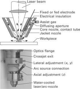
Fig 18.6 Principle (top) and practical device (bottom) of the ‘integrated hybrid welding nozzle’ [8].
18.2.4 Welding of heavy section high-strength steel plates
As with any other welding process, also the capabilities of laser-MAG hybrid welding are essentially determined by the appropriate selection of the system setup and the basic parameter configuration. If these boundary conditions are well chosen, hybrid welding proves to be a really stable, efficient and flexible technology. In the following, all welds are carried out with the above described integrated hybrid welding nozzle with an Ar-He-O2 mixture, a 20 kW CO2 laser and a programmable MAG welding source operated in the pulsed mode. In that case, the control parameters of laser, MAG and machine can be varied freely in a rather wide range in order to adjust the welding process to the required performance regarding welding depth, gap bridging, seam shape and metallurgical properties. As an example, the framed cross sections in Figs 18.7 and 18.8 indicate the parameters with the most efficient welding processes out of the respective variation, also to be recognised by the widest roots. On the other hand, in fact all cross sections in Figs 18.7 and 18.8 show very acceptable properties, which demonstrate the robustness of the selected system setup and parameter configuration.
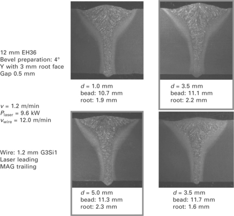
Fig 18.7 Moderate influence of distance d between laser and arc with an optimum for weld efficiency in the range of 3–5 mm [13].
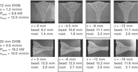
Fig 18.8 Moderate influence of focal position with an optimum for weld efficiency at focal positions within the plate [13].
There are well-defined control functions for setting welding speed, laser power and wire feed rate adapted to material thickness, groove preparation, gap width and welding position (e.g. for 15 mm plate thickness in Figs 18.9 and 18.10). It is worth mentioning, that the allowable laser power ranges to be read from Fig. 18.9 are quite wide (more than 3 kW) and even overlapping in the case of welding 15 mm in flat position PA. A control function for the laser beam power depending on gap width could in this case be dispensable and the welding speed remains constant at 1.2 m/min. Only a control of the wire feed rate adapted to the gap width is recommendable as indicated in Fig. 18.9, if an excessive weld reinforcement or underfill shall be avoided at varying gap.
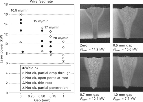
Fig 18.9 Process windows and gap bridging capability for laser-MAG hybrid welding of 15 mm structural steel in flat welding position (6° V, PA) with leading MAG at a constant welding speed of 1.2 m/min [13].
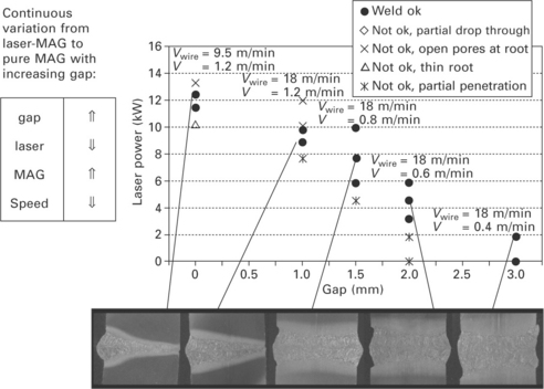
Fig 18.10 Expanded process windows and improved gap bridging capability for laser-MAG hybrid welding of 15 mm structural steel in horizontal position (6° V, PC) with leading MAG [13].
In Fig. 18.10 a phenomenon is demonstrated, which again confirms the robustness of the hybrid configuration used. With increasing gap width, the process has to be and can be continuously varied from laser-MAG hybrid welding to pure MAG welding. The transition to wide gaps up to 3 mm is achieved successfully by reducing the laser power, increasing the filler wire deposition and decreasing the welding speed in position PC. These are in fact the control functions to be considered also in practice when gap variations occur.
In the thickness range up to 25 mm, welds without any hot cracks and, if any, with only very few small pores, compliant with the highest assessment group B of EN ISO 13919–1 can be produced in a single pass [13]. Cross sections of optimised hybrid welds are presented in Fig. 18.11. In order to achieve crack-free welds, V- or Y-shaped groove preparation in the range between 4 and 8° full angle and an appropriate welding speed together with the right energy input per unit length are the crucial points to be considered. These measures ensure an ascending columnar dendrite structure upwardly curved and partly converging against the centreline in the upper MAG- dominated cup-shaped part of the seam. In the lower laser-dominated ‘trunk’ of the seam, an equiaxial grain structure is preferred, which possibly changes in the root to small columnar dendrites downwardly curved and converging against the centre line or growing down to the root surface [13].
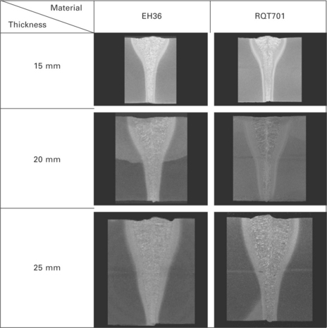
Fig 18.11 Cross sections of hybrid welded high-strength steel plates up to 25 mm thickness using a 20 kW CO2 laser at adapted power level [13].
The laser beam power as well as the welding speed must be adapted to the plate thickness and the gap width. Figure 18.12 shows a general overview of the required beam power and the achieved process capabilities regarding weldable plate thickness, welding speed and gap width for butt joints in positions PA and PC, respectively. In the thickness range between 12 and 25 mm, excellent fatigue properties of high-strength structural steel butt joints have been determined by extensive uniaxial tension and four-point bend tests (Fig. 18.13) [13].
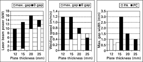
Fig 18.12 CO2-laser-MAG hybrid welding parameters and capabilities versus thickness, gap size and welding position for single-pass butt joints in structural steel [13].
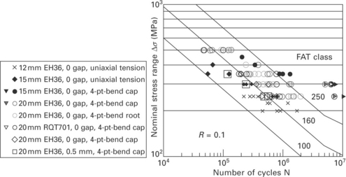
Fig 18.13 Fatigue results of heavy section laser hybrid welds [13].
18.2.5 Applications
The advantages of laser-MAG hybrid welding are increasing the thickness range of laser welding significantly. Important benefits are high welding speed, low distortion, the ability to bridge gaps, and the capability of single-pass full-penetration welding. Applications with thick wall thicknesses can be found in pipeline construction, shipbuilding, load-bearing structures, offshore engineering, special constructions and in heavy vehicle construction such as earth-moving equipment.
18.3 Combining laser welding and laser cutting
18.3.1 Multi-functional processing
Demands for innovative manufacturing techniques are high. The main targets for these techniques are greater flexibility and higher productivity at lower costs. In many cases, this seems to be impossible; nevertheless, possibilities can be discovered if process chains are analysed and consequential methods to shorten or integrate them are found [14]. Sheet metal fabrication is one example of a complex process chain. Nearly all component assemblies being manufactured from sheet metal are produced by a sequence of cutting and joining techniques. Hitherto, these different processes were carried out on different machines. The sheet components are successively prepared by cutting, joined together and, for instance, completed by cut-outs or weld- ons. If in a single machine, both cutting and welding could be performed, by this integration and shortening of the process chain, the cost of production would be reduced substantially and products could be manufactured much more flexibly.
Even the particularly flexible laser systems are usually either dedicated to a single process or valuable time is spent on changing between applications such as cutting and welding. In practice, different processes are mainly carried out sequentially on different systems. Accordingly, machine expenditure is high. Within these classical process chains a high potential of flexibility and cost savings inherent to lasers remains unutilised hitherto in industrial production.
In order to overcome these limits a so-called ‘combi-head’ allows quick switching from one process to the other and vice versa in a temporally and spatially optimised, integrated process chain. Thus, a completely new degree of flexibility is achieved in production. New designs and a large number of variants can be produced much more cost effectively by combining cutting and welding capabilities in one tool. Process and tolerance chains are shorter due to minimised material and tool handling within a single machine and due to a combi-head with a process spanning, constant tool centre point (TCP) [15].
Laser manufacturing with a combi-head is a new, highly flexible solution based on old ideas [16–20]. Some years ago, these ideas were taken up again by several groups [21–23] who were motivated by the availability of laser sources with simultaneously high power and high beam quality and by increasing market demands for flexible production. In a multifunctional laser cell, the combi-head is able to perform 3D cutting and welding tasks in an arbitrary sequence without retooling. Part handling, positioning and clamping steps are omitted. This results in shorter and more flexible process chains and with it reduced production time and costs as well as improved manufacturing accuracy [24,25]. Moreover, the combi-head opens up efficient solutions for innovative products from sheet metal with a wide range of variants.
18.3.2 The laser combi-head
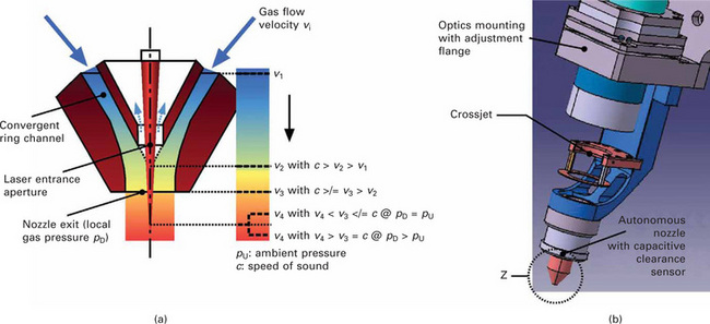
In cutting heads, coaxially to the focused laser beam, an intense cutting gas flow has to provide for effective melt ejection out of the kerf. The laser beam is guided through a high pressure nozzle in such a way that the beam focus together with the gas jet meets the workpiece below the nozzle exit (see Fig. 18.14). A lens in the laser entrance aperture of the nozzle provides for a gas-tight sealing of the nozzle chamber and focuses the laser beam. In addition, the nozzle tip serves as a capacitive clearance sensor, ensuring a constant distance to the sheet surface of about 1 mm by a closed-loop control of the machine axes.
In welding heads, with solid-state and diode lasers also lens optics accomplish focusing, but with CO2 lasers usually mirror optics are used. To create smooth shielding and process gas flow, as required for welding, mainly off-axis nozzles are applied some millimeters from the laser impingement point (see Fig. 18.14). In addition, a compressed air crossjet is arranged between the optics and the process gas nozzle that blows transversally to the laser axis in order to reliably protect the optics from smoke or spatters emitted from the weld zone. Accordingly, in contrast to the gas-tight optics of standard cutting heads, a welding head requires an open flow section below the optics, which is gas dynamically decoupled from the processing zone.
This conflict between the requirements of cutting and welding heads can be resolved with the autonomous nozzle [14] (see Plate XXIV between pages 328 and 329), which has best proved itself already in industrial applications with high-power mirror cutting heads up to 12 kW. Besides various job shops, it has also been installed at the Blohm & Voss shipyard, where it is used in a mirror cutting head for precise cutting of ship panels, which are later welded together with the same laser to produce large ship sections. In this application, a head exchange was still accepted for switching from cutting to welding and vice versa.
In principle, the idea of the autonomous nozzle is rather simple and it seems predestined for solving the conflict described in Fig. 18.14. By shifting the laser entrance aperture in the vicinity of the nozzle exit, a patented flow design enforces a minimum process gas leakage and simultaneously prevents suction of air (see Plate XXIV). That way the nozzle can produce a coaxial process gas flow in a wide pressure range, independent from the focusing optics and without a sealing window. Being ‘autonomous’, it easily permits the integration of a crossjet between itself and the focusing optics. This is necessary because the smooth process gas jet used during welding cannot protect the optics from smoke and spatters. Consequentially, a crossjet with compressed air supply, an alternating check valve for cutting and welding gas, and an appropriate numerical control program to change process parameters suffice to also make a welding head out of the cutting head. The autonomous nozzle with its rotationally symmetrical, slim design and an integrated capacitive clearance sensor represents the key component of a universal processing head for three-dimensional cutting and welding. The combi-head, as sketched in Plate XXIV, can optionally be equipped with lens or mirror optics and is suited for solid-state lasers as well as for CO2 lasers.
The main technical features of a laser combi-head as shown in Plate XXIV can be summarised as follows [14]:
• quick, software-controlled switching between cutting and welding in arbitrary sequences
• one machine, one setting, one tool for cutting (N2 and O2) and welding processes
• constant tool centre point (TCP)
• rotationally symmetrical, coaxial, and slim head design with the autonomous nozzle, integrated capacitive clearance sensor, and effective crossjet
• gas functions decoupled from the optical system
• no principle limits regarding beam power and gas pressure.
18.3.3 Impact of laser brightness
The manufacturing benefits of integrated cutting and welding with a multifunctional laser combi-head are evident. In principle, there are no differences between the capabilities and parameters of standard cutting and welding heads and the combi-head. Nevertheless, some details are worth mentioning in order to avoid needless confusion or scepticism. It is sometimes believed that adaptive optics or motorised nozzles for changing nozzle distance and focal position independently are obligatory during switching between cutting and welding. Of course these are possible options, but with the autonomous nozzle for many applications, it turned out to be appropriate to use an identical focal distance from the nozzle tip for both cutting and welding. That means focal position and nozzle distance relative to the workpiece surface are changed simultaneously, simply by lifting the complete head, when switching from cutting to welding. Fewer optical and electrical elements reduce the complexity of the combi-head to the required minimum and ensure maximum robustness. Of course the head distance as well as gas type and flow rate, laser beam power, and processing speed can be adapted automatically by the machine control being programmed accordingly.
What makes brightness relevant for combined cutting and welding is the enlarged operating window allowed for changing head distance. A ‘slim’ focal zone of a bright enough laser allows for cutting narrow kerfs with a small nozzle stand off and for excellent welding conditions with a larger stand off with the same nozzle, without changing the focal position relative to the nozzle exit [26]. A suitable beam quality and the correct layout of the collimation and focusing optics according to the demands of the combined processes are the crucial boundary conditions to be successful with the above-described concept.
18.3.4 Solutions and applications
Use of the combi-head allows precise cut edges to be produced and reliable welding of the resulting perfectly matched parts, without the need to change tools or employ a seam-tracking sensor [26]. Examples of the use of this technology include tailor-welded blanks (TWB) (Fig. 18.15) and thicker components from structural steel (Fig. 18.16).
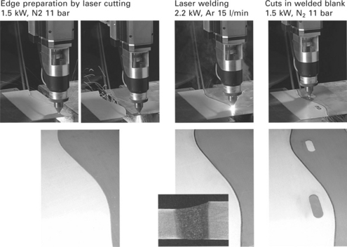
Fig 18.15 Integrated process chain for nonlinear tailored blank production (zinc-coated high-strength steel 1.0 mm/1.2 mm) using integrated laser cutting and welding with identical path concept at a speed of 8 m/min with moderate laser power; bottom pictures show processing results after the different process steps. (Photos: courtesy Fraunhofer ILT and Laserfact.)
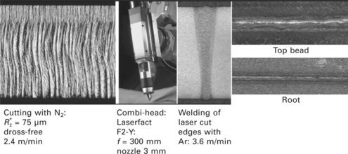
Fig 18.16 Edge preparation (oxide-free cutting with nitrogen) and welding of 8 mm structural steel plates at 8 kW with the combi-head Laserfact F2-Y, fibre-coupled to a disk laser TruDisk 8002 with a 200 μm fibre.
Particularly in the production of nonlinear tailored blanks, lack of precision in the prefabrication of the blanks causes gaps to form between the edges being joined. This can lead to either increased costs during the prefabrication phase, greater demands being made on the accuracy of seam tracking and gap measurement during the welding process, or even the use of filler material. In this context, integrated cutting and welding with the combi-head opens up new possibilities.
Figure 18.15 illustrates how a test series of blanks is prepared with the help of an industrial combi-head from Laserfact GmbH. A 4 kW fibre laser from IPG is connected to the combi-head by a process fibre with a diameter of 100 μm. The combi-head is mounted on a six-axis industrial robot. The sheets are clamped on movable linear slides, used for positioning. First of all, the edges of the blanks out of two differently galvanised car body materials with thicknesses of 1.0 and 1.2 mm are laser cut at 8 m/min and 1.5 kW, resulting in two perfectly matching edges. The edge of the first blank is then positioned against the edge of the second and the two workpieces are welded together at 8 m/min and 2.2 kW, while remaining in their original clamping device. Finally, two elongated holes located exactly to one another are cut out of the blank (see Fig. 18.15).
The integrated production flow was demonstrated to produce very high quality, even in nonlinear cuts and welds. It is particularly worth noting that the welding line can be located without a seam-tracking system, as the precise position for the weld is known to the machine coordinate system from the laser cut that precedes it. The weld line can therefore be identically (re) produced without any difficulties. This is called the ‘identical path concept’ [26].
After welding, drill-holes, contoured cut-outs or edge cuts can be performed on the metal sheets while they remain clamped. This option further enhances manufacturing flexibility and the number of different variants that can economically be produced. These subsequent cut-outs can even be made across the weld itself, resulting in a high precision component.
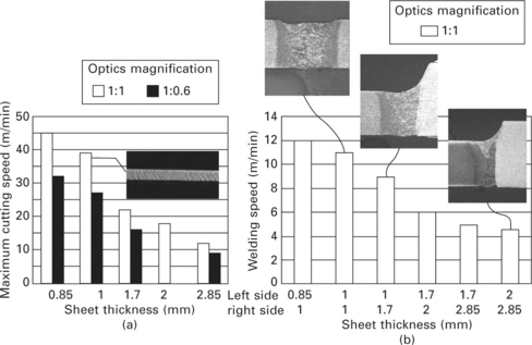
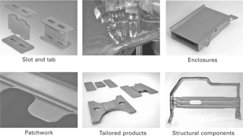
The integrated production of tailored blanks is a particularly cost-effective and flexible solution for the manufacture of small and mid-sized batches and can cope even with ultra high strength steels due to the integrated laser cutting process. Another industrial application of the combi-head is the processing of coils to produce ‘endless’ coil material in coating lines by laser trimming the ends of coils, laser welding them together and subsequent laser cutting of a smooth coil transition at the start and the end of the welded joint track. ThyssenKrupp Steel has been using a laser combi-head for this application in coil production lines in Germany and the United States since 2009. With enough laser power, the combined cutting and welding can also be managed with thicker plate or profile material, as demonstrated in Fig. 18.16. Achievable processing speeds (Fig. 18.17) and the wide spectrum of possible applications (Fig. 18.18) are the big drivers of multifunctional processing with lasers.
18.3.5 Future trends
The increased flexibility gained through combining the processes is particularly brought to bear with the utilisation of robots and fibre-coupled solid-state lasers. Combi-processing is used to manufacture 3D assemblies from 3D raw parts: deep-drawn sheets, blanks, profiles or tubes, etc. For example, the upper and lower shells of closed structures are fixed in a single clamping setup and can be welded together, sections can be cut out, and clips can be welded on in a rapid sequence of processes.
The impact of the features that support 3D performance (high beam quality, an optimised combi-head design and speed adapted laser power modulation) is demonstrated in an automotive application example, namely combi-processing of a B-pillar [26]. Driven by the use of modern high-strength materials in cars, laser trimming and cutting of holes in hot-formed parts is well established, because those materials are difficult to cut mechanically.
With the availability of combi-processing, it is only a small step to integrate the cutting process with welding operations and thus shortening the process chain. At first, several holes are cut into the B-pillar. Secondly, the final dimensions of the outer contour are cut. Next, a reinforcing sheet is welded on the pillar and, finally, holes are cut through the reinforcing sheet and the B-pillar (Fig. 18.19). All operations are performed in one clamping, thus high positional accuracy between the outer contour and the holes, including those in the weld-on part, is guaranteed.
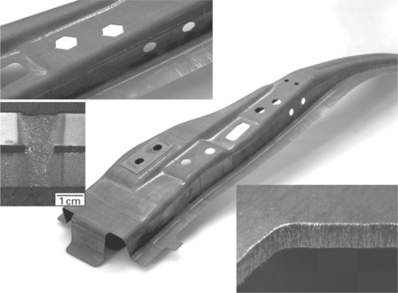
Fig 18.19 Combi-processed B-pillar with details of the welded reinforcing sheet and cut edges in small contour (hole, speed 6 m/min) and big contour (trim-cut, speed 15 m/min). (Photos: courtesy Fraunhofer ILT.)
The processing was done on a gantry robot (RLP16 from Reis) with a Laserfact combi-head F2-X (Fig. 18.20). This head is specially designed for being optimally mountable to the axes-integrated beam path of the gantry robot – without a stressed fibre connection near to the end effector. The laser source was an IPG fibre laser YLR4000 SS with a 100 mm diameter process fibre. The large contours were cut at 15 m/min, the holes at 3–9 m/min, depending on their diameter and the material thickness (thickness of the B-pillar material at least 1.4 mm). During cutting of small radii and accordingly reduced speeds of the TCP, the pulsed mode was automatically activated by properly programmed control characteristics for the speed adapted laser power modulation. The welding speed was 3 m/min for the lap weld through the reinforcement plate (1.3 mm) and the pillar (1.4 mm). The maximum laser power was 2.5 kW. Depending on the details of the cut contour, the overall processing time for cutting and welding a B-pillar as in Fig. 18.19 is in the range of 1 min.
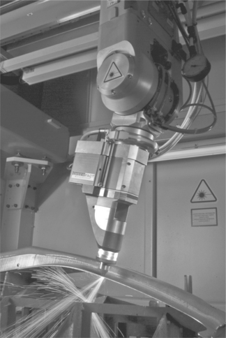
Fig 18.20 Combi-head at work. Cutting process on the B-pillar with a gantry robot. (Photo: courtesy Laserfact.)
Another demonstration of combi-processing capabilities is the possibility of overlap welding a circular seam just before cutting the hole precisely at the edge of the weld seam to produce a gap-free hole, preventing subsequent crevice corrosion (Fig. 18.21). The coordinates of the weld are known in the machine and with an identical path plus an offset, a precise position of the cut relative to the weld is possible thanks to the common TCP for cutting and welding. As both processes can be done right one after the other, there is no additional positioning.
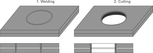
Fig 18.21 Producing a sealed overlap drill hole by laser cutting along a previously laser welded circular lap joint.
The combi-head particularly shows advantages in the following three product groups:
• complex component assemblies requiring multiple quick changes between welding and cutting operations,
• products with a wide range of variants, i.e., customised, optional cut-outs and weld-ons,
• components with a functionality that benefits from the exact positioning and orientation between cut contours and weld joints.
Combination of laser welding and laser cutting with one tool in one system can lead to the following benefits for production when manufacturing sheet component assemblies:
• short, integrated process chains for high productivity,
• high flexibility and cost-efficient production of options and variants,
• savings in handling, positioning and clamping operations,
• savings in machine investment and floor space,
• increased utilisation of the machine,
• easy reconfiguration of the system for new products,
• short tolerance chain improving accuracy of parts and components.
Taking into account the combi-head’s technical features and capabilities, it becomes obvious that investment, organisation and operation costs can be reduced by a factor of two or more in spite of equally improved productivity, time to market and flexibility. The innovative possibilities opened up by multifunctional processing are expanded as product designers and production people jointly take up this concept and combine their expertise and ideas.
18.4 References
[1] Iwase, T., Sakamoto, H., Shibata, K., Hohenberger, B., Dausinger, F. Dual focus technique for high-power Nd:YAG laser welding of aluminium alloys. Proc. SPIE. 2000; 3888:348–358.
[2] Forrest, M. G., Lu, F. Joining new auto body materials. Industrial Laser Solutions, Vol. 22. (March):2007.
[3] Bonss, S., Seifert, M., Barthel, K., Brenner, B., and Beyer, E. (2001) New developments in high power diode laser welding. Proc. 20th International Congress on Applications of Lasers & Electro-Optics, ICALEO. Jacksonville. FL, October. 2001; 15–18:2001.
[4] Petring, D., Seme, B. Oxygen cutting with annular beam. In: Bachmann F., Poprawe R., Loosen P., eds. Diode Lasers. Berlin: Springer; 2007:139–147.
[5] Perrottet, D., Green, S., Richerzhagen, B., Clean dicing of compound semiconductors using water-jet guided laser technology. The 17th Annual SEMI/IEEE Volume. Advanced Seminconductor Manufacturing Conference, 2006, ASMC. 2006; 2006:233–236.
[6] Petring, D., Wolf, N. Flexible laser process and laser system technology for the accurate manufacturing in modular rail vehicle design. ZEVrail Glasers Annalen. 2004; 128:196–201.
[7] Eboo, M., Steen, W. M., Clark, J., Arc-augmented laser welding. Proc. 4th Int. Conf. on Advances in Welding Processes, 9–11 May. 1978:257–265.
[8] Petring, D. Hybrid laser welding. December: Industrial Laser Solutions; 2001. [12–16].
[9] Lembeck, H., Laser-Hybrid-Schweißen im Schiffbau. Proceedings Aachener Kolloquium für Lasertechnik 2002, Aachen, Germany, September. 2002:177–192.
[10] Jasnau, U., Hoffmann, J., Seyffarth, P., Reipa, R., Milbradt, G., Laser-MSG-Hybridschweißen im Schiffbau. Proc. European Automotive Laser Application 2003, Bad Nauheim, Germany. 2003. [January. ].
[11] Graf, T., Staufer, H. Laser-hybrid-welding drives VW improvements. January: Welding Journal; 2003. [42–48].
[12] Petring, D., Fuhrmann, C. Hybrid laser welding: laser and arc in concert, 2003. [The Industrial Laser User, Issue 33, December, 34–36. ].
[13] Petring, D., Fuhrmann, C., Wolf, N., Poprawe, R. Progress in laser-MAG hybrid welding of high strength steels up to 30 mm thickness, Proceedings of 26th International Congress on Applications of Lasers & Electro-Optics ICALEO 2007. FL: Orlando; 2007. [300–307].
[14] Petring, D. One head does it all – new technology allows 3-D laser beam cutting and joining. August: Welding Journal; 2005. [49–51].
[15] Petring, D. Laser cutting and welding with one tool. October: The FABRICATOR; 2005. [40–41].
[16] JP 60 108 191 A publ. Japanese patent application: Working head of laser working device. 1985.
[17] GB 2 163 692 A publ. UK patent application: Laser apparatus. 1986.
[18] Felleisen, R., Kessler, B. Higher productivity by combining CO2- laser beam welding and cutting in one processing head. Proc. of ECLAT ’94, 5th European Conference on Laser Treatment of Materials, Bremen, Germany. 1994:468–474.
[19] Geiger, M., Neubauer, N., Hoffmann, P. Intelligent processing head for CO2 laser material processing. Production Engineering. 1994; 1(2):93–98.
[20] Kaplan, A. F., Zimmermann, J., Schuöcker, D., Combined laser welding, cutting and scribing. Proc. of LANE ’97, Laser Assisted Net Shape Engineering 2, Erlangen, Germany. 1997:757–766.
[21] Appendino, D. Saldatura laser flessibile di Tailored Blanks. Proc. of Expo Laser 2003, Ancona, Italy. 2003.
[22] NN: Cutting and welding with one processing optic. TRUMPF EXPRESS, July, p. 13.
[23] Schneider, F., Wolf, N., Petring, D. Cutting and welding with the ‘Autonomous Nozzle’. Fraunhofer ILT, Aachen, Germany: Annual Report; 2003. [p. 68].
[24] Schneider, F., Petring, D. Cutting and welding with a combined processing head without retooling. Fraunhofer ILT, Aachen, Germany: Annual Report; 2004. [p. 64].
[25] Schneider, F., Petring, D., Poprawe, R., Integrated laser processing – cutting and welding with a combined processing head. Proc. of LIM 2005, 3rd International WLT-Conference on Lasers in Manufacturing, Munich, Germany. 2005:133–135.
[26] Petring, D., Schneider, F. One machine does it all for laser beam welding and cutting. 2009. [Welding Journal, March, 38–41. ].
This chapter is a revised and updated version of Chapter 10 ‘Enhancing laser welding capabilities by hybridisation or combination with other processes’ by Dirk Petring, originally published in Advances in laser materials processing by J. Lawrence, J. Pou, D. K. Y Low and E. Toyserkani, Woodhead Publishing Limited, 2010, ISBN 978-184569-474-6.

