Developments in pulsed and continuous wave laser welding technologies
Abstract:
This chapter first describes the history and current status of the laser welding technology. Then, fundamentals of laser welding, such as keyhole formation and collapse, laser-plasma interaction, weld pool dynamics, porosity formation mechanisms, metal melting and solidification, etc., are elaborated. Finally, new developments in laser welding such as hybrid laser-arc welding, multi-beam laser welding, electromagnetically assisted laser welding, and future challenges and development of laser welding are discussed.
5.1 Introduction
Welding with lasers was first proposed in the early 1960s.1 After that, especially in the last two decades, laser welding has been increasingly applied to various applications in industries like automotive, shipyard, oil, etc., due to its many advantages over traditional welding techniques, such as high energy intensity, deep penetration depth; high precision and good flexibility; less distortion, etc. Much of its success is based on the development and availability of enabling technologies, which include improvements in process understanding, enhancements in laser sources and systems, and continued development and progression in process technology in laser beam welding.2
In laser welding, high power lasers such as CO2 lasers, Nd:YAG lasers, disk lasers and fiber lasers have been used or are under continuous development as a heating source.1 According to the operation mode of these lasers, laser welding can be classified as pulsed laser welding and continuous wave laser welding. For the pulsed laser welding, the typical range of pulse durations is 1–20 msec. At the lower end of this range, pulse frequencies can approach 1 kHz. For the continuous wave mode laser welding, although penetration welding is possible at high average laser powers (> 1 kW), this condition is not always obtainable at low average power. The CO2 laser is the workhorse of industrial laser welding systems because it is simple and reliable with output powers up to 50 kW. It has higher output efficiency compared with other lasers, such as the Nd:YAG laser. The generation of high average power in Nd:YAG laser systems is accomplished by combining several individually pumped laser rods in a single resonator. One of the prime advantages of the Nd:YAG laser over the CO2 laser is its ability to deliver laser radiation through optical fibers, which makes it very attractive in robotic or multiaxis laser welding applications. With fiber-optic coupling, it is also possible to combine the power from two or more lasers.
In recent years, many new developments and applications have occurred in laser welding, which includes the use of new laser source systems and laser welding process technologies.2 In terms of the laser source, diode lasers and diode pumped solid-state lasers have been the subject of innovative developments in the last decade. Most recently high power diode pumped fiber lasers were developed with attractive characteristics for materials processing applications. High-power fiber lasers can be used for deep penetration welding of various materials since its characteristic low wavelength allows its absorption by almost all metals and alloys, and the fiber delivery system provides the necessary flexibility on the positioning of the beam.
The first use of fiber lasers dates back to the early 1960s, when low-power lasers were used in optical amplifiers. The first 100 W fiber laser was produced for materials processing in 2000.3 Multi-kilowatt fiber lasers have now been introduced for materials processing and the maximum power from commercial fiber lasers can reach 100 kW. Multi-kilowatt power levels are achieved by combining the output from several single mode fiber lasers. The technology is under development to produce systems of even higher power. These new lasers have multiple advantages including high efficiency compared to lamp or diode pumped rod lasers; compact design; good beam quality due to the use of small diameter fibers, and thus small beam focus diameter; and a robust setup for mobile applications. The lifetime of the pumping diodes is expected to exceed the lifetime of other diode pumped lasers which leads to low cost.3 In order to understand these new developments and continue to optimize the laser welding process for its current applications and expand its capacity into more applications, it is crucial to have a good understanding of the fundamental physics involved in laser welding. Then, the current developments and future trend in laser welding will be discussed.
5.2 Fundamentals of laser welding
Laser welding involves a lot of complicated physical processes including metal melting and solidification; keyhole formation and collapse; keyhole plasma formation and laser-plasma interaction, which results in very complex transport phenomena in the welding process.4 As is well known, metallurgical structure and mechanical properties of the laser weld are strongly dependent on transport phenomena such as heat transfer, melt flow, and plasma flow in the welding process.5–9 In the following section, major transport phenomena involved in laser welding will be discussed to understand the scientific fundamentals in the laser welding process. Special attention is given to discussions on: laser-induced keyhole plasma formation and energy transport in plasma; recoil pressure and mechanisms contributing to keyhole formation; keyhole collapse and solidification process; porosity formation; and metal melting and solidification process.
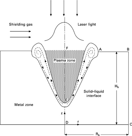
Due to the different nature of heat and mass transfer mechanisms in metal and plasma, different mathematical models have been developed to study the fundamental physics in laser welding. As shown in Fig. 5.1, one has been developed to study the transport phenomenon in the metal region containing base metal. The other is for the study of the keyhole region containing laser-induced plasma. There is a free surface (liquid/vapor interface) separating these two regions. For the metal region, continuum formation is used to calculate the energy and momentum transport.10 For the keyhole plasma region, laser-plasma interaction and the laser energy absorption mechanism are discussed. These two regions are coupled together and the volume-of-fluid (VOF) technique is used to track the interface between these two regions.10
5.2.1 Transport phenomena in metal
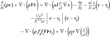
Differential equations governing the conservation of mass, momentum and energy based on continuum formulation are given below.10
where t is the time, ρ is the density, and V is the velocity vector.
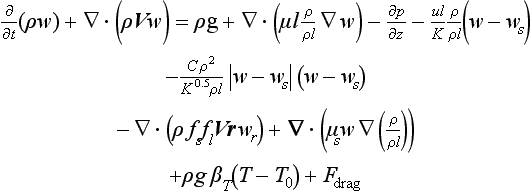
where u, v and w are the velocities in the x-, y- and z-directions, respectively, and Vr is the relative velocity vector between the liquid phase and the solid phase. The subscripts s and l refer to the solid and liquid phases, respectively; Subscript 0 represents the reference conditions; p is the pressure; μ is the viscosity; f is the mass fraction; K, the permeability, is a measure of the ease with which fluid passes through the porous mushy zone; C is the inertial coefficient; βT is the thermal expansion coefficient; g is the gravitational acceleration; and T is the temperature.
where h is the enthalpy, k is the thermal conductivity, and cp is the specific heat. The first two terms on the right-hand side of Eq. [5.5] represent the net Fourier diffusion flux. The third term represents the energy flux associated with the relative phase motion.
The third and fourth terms on the right-hand side of Eqs [5.2]–[5.4] represent the first- and second-order drag forces of the flow in the mushy zone. The fifth term represents an interaction between the solid and the liquid phases due to the relative velocity. The second term on the right-hand side of Eq. [5.5] represents the net Fourier diffusion flux. The third term represents the energy flux associated with the relative phase motion. All these aforementioned terms in this paragraph are zero except in the mushy zone. In addition, the solid phase is assumed to be stationary (VS = 0).
where D is a mass diffusivity and fα is a mass fraction of constitute. Subscripts l and s, represent liquid and solid phase, respectively.
5.2.2 Transport phenomena in laser-induced plasma
The vapor inside the keyhole is modeled as a compressible, inviscid ideal gas. No vapor flow is assumed in the keyhole and the energy equation is given in the following form:11
where hv and ρv represent the enthalpy and density of the plasma; kv and cv represent the thermal conductivity and specific heat of the plasma. The first term on the right-hand side of Eq. [5.7] represents the heat conduction term. The second term represents the radiation heat term and qr stands for the radiation heat flux vector. The fourth term represents energy input from the original laser beam. The last term represents the energy input from multiple reflections of the laser beam inside the keyhole.
5.2.3 Laser-induced recoil pressure and keyhole formation
In the laser welding process, when the laser beam is directed on the surface of the workpiece, it first melts the metal, forming a small molten pool in the workpiece. With the continuous heating from the laser beam, the liquid metal is then heated to high temperatures resulting in large evaporation rates. When the metal vapor escapes from the liquid metal, it exerts a pressure called recoil pressure to the liquid metal surface. This recoil pressure will depress the molten metal downward and then a cavity in the liquid metal known as keyhole will be formed. Many investigators believe that this recoil pressure combined with surface tension force is the main factor determining the shape of the keyhole. So, understanding the recoil pressure formation is critical for understanding the keyhole formation and thus for the control of the laser welding process. As known, the recoil pressure results from the rapid evaporation from a metal surface that has been heated to high temperatures. When the liquid–vapor interface temperature reaches boiling point, evaporation begins to occur. As shown in Fig. 5.2, there is a Knudsen layer adjacent to the liquid metal surface. In the Knudsen layer, the metal vapor escaping from the liquid surface is in a state of thermodynamic non-equilibrium, i.e., the vapor molecules do not have a Maxwellian velocity distribution. This occurs when the equilibrium vapor pressure (i.e., the saturation pressure) corresponding to the surface temperature is large compared to the ambient partial pressure of the vapor. Under these conditions the vapor adjacent to the surface is dominated by recently evaporated material that has not yet experienced the molecular collisions necessary to establish a Maxwellian velocity distribution. The Knudsen layer is estimated to be a few molecular mean free paths thick in order to allow for the molecular collisions to occur that bring the molecules into a state of translational equilibrium at the outer edge of the Knudsen layer.
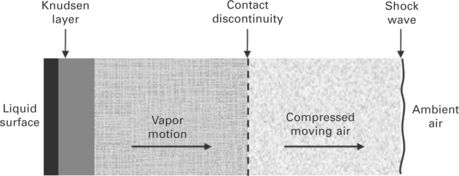
5.2 A schematic of the gas dynamic of vapor and air away from a liquid surface at elevated temperature.
Anisimov12 and Knight13 did the early investigations on the Knudsen layer. A kinetic theory approach14 is used to study the behavior of this layer. The analysis proceeds by constructing an approximate molecular velocity distribution adjacent to the liquid surface. Equations describing the conservation of mass, momentum and energy across the Knudsen layer are developed in terms of this velocity distribution. This gives Eqs [5.8] and [5.9], as given below, for gas temperature, TK, and density, ρK, outside of the Knudsen layer as functions of the liquid surface temperature and the corresponding saturation density, ρsat.
The quantity, m, is closely related to the Mach number at the outer edge of the Knudsen layer, MK, and is defined as ![]() , where γV and RV are the ratio of specific heats and the gas constant for the vapor, respectively. The value of m depends on the gas dynamics of the vapor flow away from the surface. The gas temperature, pressure and density throughout the vapor region (outside of the Knudsen layer) are uniform. The contact discontinuity, that is, the boundary between vapor and air, is an idealization that results due to the neglect of mass diffusion and heat conduction. The velocity and pressure are equal in these regions, uK = uS and PK = PS, where the subscript, S, denotes properties behind the shock wave. Note that, in general, TK ≠ TS and ρK ≠ ρS.
, where γV and RV are the ratio of specific heats and the gas constant for the vapor, respectively. The value of m depends on the gas dynamics of the vapor flow away from the surface. The gas temperature, pressure and density throughout the vapor region (outside of the Knudsen layer) are uniform. The contact discontinuity, that is, the boundary between vapor and air, is an idealization that results due to the neglect of mass diffusion and heat conduction. The velocity and pressure are equal in these regions, uK = uS and PK = PS, where the subscript, S, denotes properties behind the shock wave. Note that, in general, TK ≠ TS and ρK ≠ ρS.
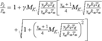
The thermodynamic state and velocity of the air on each side of the shock wave are related by the Rankine-Hugoniot relations, where the most convenient forms to this application are given by Eqs [5.10] and [5.11]. MK is the Mach number in the vapor, ![]()
The saturation pressure, Psat, is obtained from Eq. [5.12], where A, B and C are constants which depend on the material. This is used to obtain the saturation density, ρsat = Psat/(RVTL), assuming an ideal gas.
Eqs [5.8]–[5.12] are solved as a function of TL using an iterative solution method. The vapor is assumed to be iron in the form of a monatomic gas with a molecular weight of 56, and γV = 1.67. Quantities of particular interest are the recoil pressure, Pr, and rate of energy loss due to evaporation, qe, and they are given by:
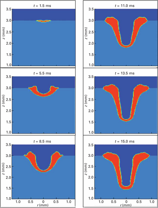
The effect of recoil pressure and surface tension on the keyhole formation can be clearly seen in Plate I (between pages 328 and 329).11 As shown, at the initial stage (t < 1.8 ms), the laser energy is mainly used to heat up the base metal. As the temperature of the base metal increases, a small weld pool starts to appear under the laser beam. When the laser power reaches its peak value (after 1.0 ms), the laser-induced recoil pressure starts to push down the molten metal under the laser beam. Since it takes time to accelerate the molten metal from a static condition and the weld pool is thin at this time, the surface of the weld pool is nearly flat. Only part of the laser energy is absorbed by the metal via Fresnel absorption (to be discussed later) and the rest of the laser energy is reflected away. Heat conduction is the major heat transfer mode at this stage. As the laser light continues to radiate the metal, the temperature of the weld pool surface increases. The large temperature difference along the free surface of the weld pool due to the Gaussian distribution of laser power leads to a high temperature-dependent Marangonishear stress. Since the gradient of surface tension coefficient on temperature change is negative when T is above 2150 K, the temperature-dependent Marangoni shear stress is positive along the weld pool surface, which drives the fluid to flow outwards. In the surface area where temperature is below 2150 K, surface tension coefficient gradient will change to be a positive value. Since the temperature gradient is still negative, the Marangoni shear stress forces the liquid metal to flow inwards. A crater is then formed at some point of the weld pool where the temperature is above 2150 K, as shown in Plate II (between pages 328 and 329). Moreover, higher surface temperature leads to higher recoil pressure, which pushes the liquid metal under laser radiation downwards quickly. Although the liquid–solid interface keeps moving downwards, the liquid region of the weld pool under laser radiation remains only as a thin layer because the strong recoil pressure squeezes the liquid metal to flow outwards. Under the hydrodynamic force and the Marangoni shear force, the squeezed liquid metal flows upwards along the keyhole wall which facilitates the formation of a crater. As the liquid surface moves down and the crater level increases, a keyhole appears in the weld pool at t = 6.0 ms.
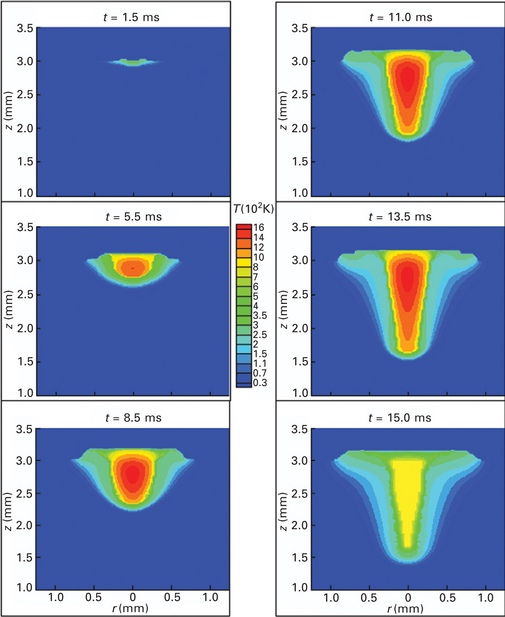
Plate II Keyhole plasma formation and corresponding temperature distributions as shown in Plate I.
5.2.4 Laser-plasma interaction and multiple reflections of laser beam in keyhole
In the laser welding process, the laser beam is reflected several times inside the keyhole by the keyhole wall. Also, each time the laser beam travels inside the keyhole, it interacts with the keyhole plasma. Multiple reflection of the laser beam by the keyhole wall and absorption mechanism of the laser energy by the keyhole plasma (Inverse Bremsstrahlung absorption) and by the keyhole wall (Fresnel absorption) are critical in determining the energy distribution and are discussed below.
Inverse Bremsstrahlung (IB) absorption
As discussed above, with the continuous heating from the laser beam, the metal vapor inside the keyhole can be heated much above its evaporation temperature, resulting in strong ionization. Thus, keyhole plasma is produced. The resulting keyhole plasma can absorb a lot of laser power by the effect of Inverse Bremsstrahlung (IB) absorption, thus affecting the energy transport to the liquid metal. Equations [5.14] and [5.15] define the IB absorption fraction of laser beam energy in plasma by considering multiple reflection effects:15
where, αiB,1 is the absorption fraction in plasma due to the original laser beam; αiB,mr is the absorption fraction due to the reflected laser beam. ![]() are, respectively, the optical thickness of the laser transportation path for the first incident and multiple reflections, and kpl is the plasma absorption coefficient due to Inverse Bremsstrahlung absorption:16
are, respectively, the optical thickness of the laser transportation path for the first incident and multiple reflections, and kpl is the plasma absorption coefficient due to Inverse Bremsstrahlung absorption:16
where Z is the average ionic charge in the plasma, ω is the angular frequency of the laser radiation, ε0 is the dielectric constant, k is the Boltzmann’s constant, ne and ni are particle densities of electrons and ions, h is Planck’s constant, me is the electron mass, Te is the excitation temperature, c is the speed of light, and ![]() is the quantum mechanical Gaunt factor. For the weakly ionized plasma in the keyhole, the Saha equation16 can be used to calculate the densities of plasma species:
is the quantum mechanical Gaunt factor. For the weakly ionized plasma in the keyhole, the Saha equation16 can be used to calculate the densities of plasma species:
Fresnel absorption
As discussed before, part of the laser energy will be absorbed by keyhole plasma and part of the laser energy can reach the keyhole wall directly. So, the energy input (qlaser) for the keyhole wall consists of two parts: Fresnel absorption of the incident intensity directly from the laser beam (Iα,Fr) and Fresnel absorption due to multiple reflections of the beam inside the keyhole (Iα,mr):
where Ilaser is the incoming laser intensity and n is the total number incident light from multiple reflections. We assume the laser beam has in the simplest case a Gaussian-like distribution:
where rf is the beam radius and rf0 is the beam radius at the focal position; I0 is the peak intensity.αFr is the Fresnel absorption coefficient and is defined by the following formula:17
where φ is the angle of incident light with the normal of keyhole surface, and ε is a material-dependent coefficient.
Plate II (between pages 328 and 329) shows a typical keyhole plasma formation process and the effect of keyhole plasma on energy transport in laser welding.11 As shown, once the keyhole comes into being, some metal vapor will be trapped inside. The incoming laser beam interacts with this metal vapor and part of laser energy is absorbed by it. Since the heat capacity of the vapor is rather low, the temperature of the vapor increases very quickly. When the temperature of the metal vapor exceeds around 8,000 K, laser-induced plasma will be formed by the ionization process. The physical properties of plasma are quite different from that of the prior vapor, which absorbs more laser energy through the IB absorption process. Once the keyhole plasma comes into being, it plays two roles in keyhole formation. The coefficient of the IB absorption increases with the increase of plasma temperature11. Hence, once plasma forms, its temperature will increase very quickly. This hot plasma separates the keyhole wall from the cold shielding gas, which reduces the heat loss from the keyhole wall to the surroundings. Moreover, the hot plasma heats up the surrounding keyhole wall via radiation. This facilitates the temperature increase on the keyhole wall when the depth of keyhole is not large. As shown in Plate II (between pages 328 and 329), the temperature on the keyhole wall under laser radiation keeps increasing. Therefore, the recoil pressure becomes stronger accordingly, which helps the depth of keyhole grow very quickly. However, when the plasma temperature is above 10,000 K, the IB absorption coefficient decreases with the increasing plasma temperature. Although the coefficient of the IB absorption decreases with the small increase of plasma temperature, the travel length of laser light increases with the increasing keyhole depth, the overall effect of the plasma absorption becomes more and more remarkable, and it will block a greater percentage of the laser energy from reaching the keyhole bottom wall. Meanwhile, the temperature of plasma only increases a little. The heat radiation from the plasma also increases a little correspondingly.
Thus, the blocking effect on laser light becomes more and more dominant, which eventually will make the plasma become a negative factor for keyhole depth increase at a certain time.
The formation of the keyhole also enhances the laser light absorption through a mechanism called multiple reflections. As shown in Plate I (between pages 328 and 329), the surface of the weld pool is nearly flat at the beginning. Once laser light irradiates the flat surface, only part of the energy is absorbed by the surface via the Fresnel absorption mechanism. A large amount of the laser energy is reflected back. Since the direction of the reflected light is contrary to its incident direction, this part of the laser light will never reach the weld pool surface again. However, once the keyhole is formed, the surface along the keyhole wall is not flat. Part of the reflected light will be incident on the keyhole wall again and again. During each incidence, part of the laser energy is absorbed via the Fresnel absorption mechanism. This brings more laser energy input to the keyhole wall, which leads to higher recoil pressure on the keyhole wall. Moreover, as the keyhole deepens, the possibilities and times of multiple reflections increase. When the reflected laser light travels in the plasma, part of its energy will also be absorbed by the plasma to increase the plasma temperature.
5.2.5 Radiative heat transfer in laser-induced plasma
When an intense laser beam interacts with metal vapor, a significant amount of the laser radiation is absorbed by the ionized particles. The radiation absorption and emission by the vapor plume may strongly couple with the plume hydrodynamics. This coupling, shown on the right-hand side of Eq. [5.7], will affect the plasma laser light absorption and radiation cooling terms. The radiation source term ∇ · (− qr) is defined by
where ka, Ib and Ω denote the Planck mean absorption coefficient, blackbody emission intensity and solid angle, respectively. For the laser-induced plasma inside the keyhole, the scattering effect is not significant compared with the absorbing and emitting effect. So it will not lead to large errors to assume the plasma is an absorbing-emitting medium. The radiation transport equation (RTE) has to be solved for the total directional radiative intensity I:18
where s and r denote a unit vector along the direction of the radiation intensity and the local position vector. The Planck mean absorption coefficient is defined in the following:18
where nt and ne represent the particle density of ions and electrons, Tv is the temperature of the plasma, Z stands for the charge of ions, e is the proton charge and me is the mass of electrons.
5.2.6 Tracking of free surfaces
The algorithm of volume-of-fluid (VOF) is used to track the moving free surface.10 The fluid configuration is defined by a volume of fluid function, F(x,y,z,t), which is used to track the location of the free surface. This function represents the volume of fluid per unit volume and satisfies the following conservation equation:
When averaged over the cells of a computing mesh, the average value of F in a cell is equal to the fractional volume of the cell occupied by the fluid. A unit value of F means a cell full of fluid and a zero value indicates a cell containing no fluid. Cells with F values between zero and one are partially filled with fluid and identified as surface cells.
5.2.7 Melt flow and weld pool dynamics
Figure 5.3 shows the melt flow and weld pool dynamics in a typical laser keyhole welding process.11 As known, in laser keyhole welding, the weld pool is subject to strong recoil pressure and Maragoni shear stress, which introduces complex melt flow in the weld pool. As shown, at the beginning of a laser welding process, since the weld pool is small and also it takes time to accelerate the molten metal, the melt flow is not significant. Once the keyhole is formed, due to the strong push from the laser-induced recoil pressure, some strong velocities appear in the weld pool. On the bottom of the keyhole wall, the strong push from the recoil pressure leaves a very thin layer of liquid there. Although the hydrostatic pressure and surface tension at the bottom of the keyhole become larger and larger as the keyhole deepens, which makes it difficult for the drilling process, the velocity of liquid along the bottom surface does not decrease, as shown in Fig. 5.3. Meanwhile, the hydrostatic pressure at the bottom of the keyhole increases as the keyhole deepens, which makes it more and more difficult for the recoil pressure to pump the liquid upwards. Moreover, the temperature difference along the sidewall of the keyhole decreases as the keyhole depth increases.
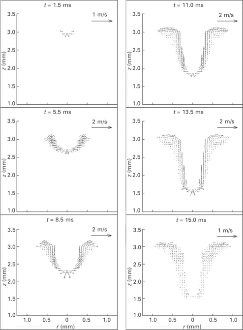
5.3 Weld pool dynamics and corresponding velocity distribution as shown in Plate I.
This decreases the Marangoni shear stress and makes it more difficult for the squeezed liquid metal to flow upwards. As shown in Fig. 5.3, both the downward velocities at the bottom keyhole and the upward velocities along the sidewall of the keyhole are smaller at t = 13.5 ms compared with those at t = 11.0 ms. At this time, since more laser energy is absorbed by the keyhole plasma, especially by that in the upper part of the keyhole, this hot plasma increases the heat input to the keyhole wall. Meanwhile, the multiple reflections also bring more and more energy to the sidewall of the keyhole as the keyhole deepens. As shown in Plate I (between pages 328 and 329), the increased heat input to the sidewall of keyhole causes the liquid–solid interface in the keyhole to move outwards, which enlarges the heat-affected zone in the weld substrate. Hence, the liquid region of the keyhole is getting bigger at t = 15.0 ms compared with that at t = 13.5 ms and the keyhole depth does not increase remarkably at this period. Also, the liquid metal on the bottom of the keyhole is getting thicker. This is because, with more and more laser energy being absorbed by the plasma, the recoil pressure on the bottom of the keyhole is decreasing at t = 15.0 ms, hence more liquid metal is accumulated there.
As also noticed in Fig. 5.3, there is a vortex in the upper part of the weld pool at t = 13.5 ms. The formation of the vortex is the result of the combined action of four driving forces: temperature-dependent Marangoni shear stress, surface tension, hydrodynamic force, and hydrostatic force. On the upper part of the vortex, the liquid is driven from the hot edge to the cold edge by the Marangoni shear stress force when the temperature of liquid is above 2,150 K. As the liquid metal moves to the cold edge, the temperature gradient becomes smaller and smaller which makes the Marangoni shear stress decrease. At the point where the liquid temperature is under 2,150 K, the Marangoni shear stress will change its direction. This change prevents the liquid from moving outwards. At the same time, the surface tension on the cold edge also blocks the liquid to flow outwards. Therefore, the velocity vector along the r-direction becomes smaller and smaller. Meanwhile, the hydrostatic force and surface tension cause the liquid to flow downwards, which makes the velocity along the z-direction become larger and larger. Finally, the liquid metal changes its flow direction to flow downwards at the upper of the cold edge. When this downward-flowing liquid metal meets the liquid–solid interface, it is blocked by this interface and flows along the interface. Meanwhile, the hydrodynamic force of the squeezed liquid from the lower part of the keyhole makes the liquid flow upwards. Thus, the liquid changes its direction to flow upwards at the lower part of the hot edge. As the liquid flows upwards, the hydrodynamic force is counteracted by the hydrostatic force and surface tension, which retards the upward tendency. Meanwhile, the Marangoni shear stress pushes the liquid to flow toward the cold edge. Thus, the liquid flow rotates clockwise on the shoulder of the keyhole and a vortex is formed as shown in the figure. This vortex enhances the heat transfer along the liquid–solid interface and enlarges the liquid region on the shoulder of the keyhole.
5.2.8 Keyhole collapse and porosity formation
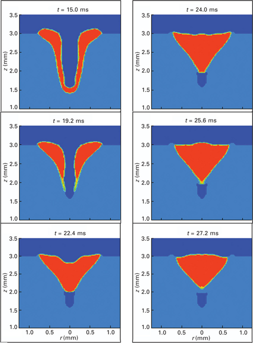
Plate III (between pages 328 and 329) shows a typical keyhole collapse process in laser welding.19 As shown, once the laser is shut off, the hot plasma radiation is the only heat input source for the keyhole wall. However, since there is no heat input to the plasma and the heat capacity of plasma is very small, the temperature of the plasma drops very quickly. Meanwhile, the heat conduction from the keyhole wall to the surrounding metal is very strong due to the high aspect ratio and high temperature gradient. Hence, the temperature of the keyhole wall drops very quickly, especially in the lower part of the keyhole since there is only a thin layer of the metal liquid there. Due to this quick temperature drop, the thin layer of liquid metal on the bottom of the keyhole completely solidifies. At this time, the temperature gradient along the sidewall surface of the keyhole is negative from the bottom to the top and the temperature of the liquid metal is above 2,150 K. Thus, the Marangoni shear stress is still positive, which helps the liquid to flow upwards. Since the temperature of the metal on the bottom surface drops much faster than that on the upper surface, the Marangoni shear stress there decreases quickly. Meanwhile, the hydrodynamic pressure of the squeezed liquid metal also decreases very quickly due to the removal of recoil pressure. The surface tension and hydrostatic pressure then make the liquid metal have a tendency to fill back the keyhole. However, the velocity of liquid metal needs time to change its direction, especially on the lower part of the keyhole wall due to their original high velocities inertia. On the keyhole shoulder, the Marangoni shear stress also decreases quickly with the decreasing temperature gradient. Hence, with the action of hydrostatic pressure and surface tension, the liquid metal on the upper part of the keyhole starts to flow inwards and downwards at t = 15.5 ms. Since there is a certain amount of liquid metal there and the flow friction along the liquid–solid interface is larger for the thin liquid layer, the backfilling velocities of the liquid metal on the upper part will be accelerated more easily than those on the lower part of keyhole. Thus, the keyhole is closed on the top first as shown in the figure. Meanwhile, the liquid metal continues to be accelerated by the hydrostatic force to flow downwards along the keyhole wall and finally the keyhole is refilled at t = 30.0 ms. The liquid region also shrinks as the liquid refills the keyhole, especially at the bottom because of fast conduction heat loss and low heat capacity. Finally, the liquid metal on the bottom completely solidifies. During the keyhole collapse process, the hot liquid metal cannot reach the far end of the top surface due to the disappearance of recoil pressure. Moreover, the velocity of the liquid metal flowing toward the edge decreases during the backfilling process. Thus, the liquid metal at the far end of the top surface cannot fill back and solidifies there, which results in a rough top surface on the final weld, as shown in Plate III (between pages 328 and 329) at t = 30.0 ms.
Compared with conventional welding processes, keyhole mode laser welding is more promising due to its large depth-to-width aspect ratio capability and high welding efficiency. However, in deep penetration laser welds, porosity is frequently observed.20–23 Porosity deteriorates the strength of the welded part. Over the years, research has been conducted to study the porosity formation mechanisms in laser welding. Katayama et al.24 reported that a lot of pores/voids were formed due to the entrainment of shielding gas or metal vapor and/or the dissolution of gas (for example, hydrogen) during the fast solidification process in high power YAG laser welding of A5083 alloy and 304 steel. Seto et al.25 found that the rear side of the molten metal was depressed near the bottom when the keyhole front was inclined in the rear direction at the root. The reflected laser beam can superheat the molten metal near the bottom, resulting in a depression due to the high recoil pressure acting on the molten metal. They concluded that the shape of the keyhole front had a significant influence on porosity formation.
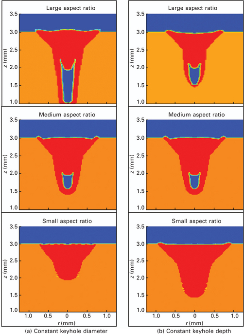
Katayama et al.26 also found that the formation of porosity had a close correlation with the collapse of the keyhole in their studies of the fusion and solidification behavior of a molten puddle during laser spot welding of Type 316 stainless steel. Once the laser beam was terminated, the melt in the upper part of the keyhole flowed downward to fill the keyhole. Some gas seems to have been trapped in the lower part of the keyhole. At the same time, the upper part of the melt rapidly solidified, which prevented the melt from flowing to fill the keyhole. Thus porosity was formed in the weld. Zhou and Tsai.19 found that porosity formation in laser welding is associated with the weld pool dynamics, keyhole collapse, and solidification processes, as shown in Plate III (between pages 328 and 329). More specifically, formation of porosity in pulsed laser welding was found to be due to two competing factors: one is the solidification rate of the molten metal and the other is the backfilling speed of the molten metal during the keyhole collapse process.19 Porosity will be formed in the final weld if the solidification rate of the molten metal exceeds the backfilling speed of liquid metal during the keyhole collapse and solidification processes. As shown in Plate IV (between pages 328 and 329), porosity formation was found to be strongly related with the depth-to-width aspect ratio of the keyhole.19 The larger the ratio, the easier porosity will be formed, and the larger the size of the voids.
5.3 New developments in laser welding
5.3.1 Hybrid laser-arc welding
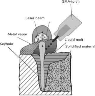
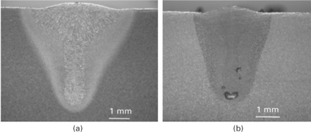
In the last two decades, one of the major developments in laser welding has been the development of hybrid laser-arc welding technique and its applications in many areas in engineering.27,28 As shown in Fig. 5.4, in hybrid laser-arc welding, the laser and the arc are integrated to provide primary and secondary heating sources for the joining process. Due to the synergistic action of the laser beam and welding arc, hybrid welding offers many advantages over laser welding and arc welding alone,29,30 such as higher welding speed, deeper penetration,31 better weld quality with reduced susceptibility to pores and cracks,32–40 good gap bridging ability,41–46 as well as process stability and efficiency, as shown in Fig. 5.5.31
The development of the hybrid laser-arc welding technique can be divided into three stages.27 The concept of hybrid laser welding was first proposed by Steen et al.47–49 in the late 1970s. In their studies, a CO2 laser was combined with a tungsten inert gas (TIG) arc for welding and cutting applications. Their tests showed clear benefits of combining an arc and a laser beam, such as stabilized arc behavior under the influence of laser radiation; a dramatic increase in the speed of welding of thin sheets; and an increase in penetration depth compared with laser welding. Japanese researchers continued Steen’s efforts and developed various methods and corresponding devices for laser-arc welding, cutting, and surface treatment. However, these efforts did not result in the introduction of this joining technique into engineering applications, particularly because laser welding itself was not yet an economic and viable joining technique at that time.50
In the second stage of the development of the hybrid laser welding technique, the observed influencing of the arc column behavior by laser radiation was used to improve the efficiency of arc welding processes, which leads to the laser enhanced arc welding technology.27 A characteristic feature of this technology was that only a low-intensity laser beam was needed, i.e., the required laser power was small compared to the arc power. For TIG welding, Cui, Decker et al.,51–53 demonstrated that a low-energy CO2 laser beam with a power of merely 100 W could facilitate arc ignition; enhance arc stability; improve weld quality; and increase welding speed due to a reduced arc size and higher arc amperages. However, despite such reported improvements of the arc welding process by laser support, there were neither subsequent extensive investigations of this subject nor known industrial applications of the laser-enhanced arc welding technology.
The third stage of hybrid welding technology started in the early 1990s with the development of combined welding processes using a high-power laser beam as the primary and an additional electric arc as the secondary heating source.54–62 At that time, although the continuous wave CO2 laser welding process was already well established in industry, it had some known disadvantages, e.g., high requirements of edge preparation and clamping; high solidification rates leading to material-dependent pores and cracks; as well as the high investment and operating costs for the laser equipment. Additionally, some welding applications of highly practical interest could not be solved satisfactorily by the laser welding process alone, e.g., joining of tailored blanks in automotive engineering; welding of heavy plate under the conditions of the shipbuilding industry; as well as high-speed welding of crack-susceptible materials. In searching for suitable solutions, a hybrid welding technique was developed into a viable joining technique with significant industrial acceptance during the last decade.
According to the combination of various heating sources used, hybrid welding can be generally categorized as: (1) laser-gas tungsten arc (GTA) welding; (2) laser-gas metal arc (GMA) welding; and (3) laser-plasma welding.25 Since laser welding offers deep penetration, primary heating sources commonly used in hybrid welding are CO2, Nd:YAG, and fiber lasers.
The first two types of lasers are well established in practice and used for various hybrid welding process developments. While the fiber laser is still in development for industrial applications, it seems to be a future primary heating source for hybrid welding due to its high beam quality. The secondary heating sources used in hybrid welding are mainly electric arcs. Dedicated processes can be divided into GMA welding with consumable electrodes and GTA welding with non-consumable tungsten electrodes. In GMA welding, the arc is burning between a mechanically supplied wire electrode and the workpiece. The shielding gas used in GMA welding was found to have significant effects on arc shape and metal transfer.63’64 Hence, GMA welding can be subdivided into metal inert-gas (MIG) and metal active-gas (MAG) welding according to the type of shielding gas used. In GTA welding, a chemically inert gas, such as argon or helium, is often used. A special form of this is the plasma arc welding (PAW), which produces a squeezed arc due to a special torch design and results in a more concentrated arc spot.
In hybrid welding, the laser and arc are arranged preferably in a way that they can compensate and benefit from each other during the welding process, which implies the creation of a common interaction zone with changed characteristics in comparison to laser welding and arc welding alone. In contrast to this is the arrangement in which the laser and arc are serving as two separate heating sources during the welding process. Several configurations have been proposed. In a parallel arrangement, there is a distance in either the vertical or horizontal direction along the path between both heating sources. In a serial arrangement, the primary and secondary heating sources are moved along the same welding path with a certain working distance, and the secondary heating source can either lead or follow the primary heating source.27 The first one enables a preheating of the region to be welded. It can increase the efficiency of the laser welding process because the material to be welded is locally preheated and energy losses by heat conduction are reduced. In comparison, the second one often acts like a short-time post-heat treatment of the weld that can change the weld microstructure favorably. It is worth considering that there is an essential difference between parallel and serial process arrangements. In a serial arrangement, additional energy is dissipated within the weld seam region, whereas the parallel arrangement only reduces the heat flow across the weld seam. The option to move the working area temporally enables flexibility in influencing the cooling rates in order to avoid defects.
In recent years, hybrid laser-arc welding has been increasingly used to join aeronautical materials, the benefit mainly originates from the ability of this process to adjust filler metal additions, heat input, and post heat treatment processes. Although some initial successes have been obtained to join aeronautical materials, like stainless steels, titanium, magnesium, and aluminum alloys, in-depth research, rigorous characterization, and cost analysis are still needed. Hybrid welding of these alloys often involves combinations of different filler and base metals, which have to be determined for various hybrid welding conditions in order to obtain optimum weld properties. Detailed characterization of structure and properties for each alloy remains a major task and rigorous studies need to be carried out to understand the correlation between welding conditions and the resulting weldment structure and properties for these important engineering alloys. Hence, the applications of hybrid laser-arc welding technique can be widened in aerospace engineering.
Although hybrid laser-arc welding has been gaining increasing acceptance in recent years, good understanding of the underlying physics remains a challenge. For example, the interaction between the laser and the arc has been observed to enhance arc stability and push the arc towards the laser keyhole, resulting in a deeper penetration. However, the origin of this synergistic interaction between the arc and laser plasma is not well understood. Measuring the distributions of electron temperatures and densities in the plasma can provide a better understanding of the laser-arc interaction.9 Porosity formation is believed to be strongly related to the keyhole collapse process. Hence, better understanding of keyhole stability and dynamics through experimental and theoretical studies would be beneficial. Hybrid welding is known to produce welds with desirable widths and depths, but the maximum gap tolerance and weld penetration for various welding conditions have not been quantified. In the future, advanced mathematical modeling of the heat transfer and fluid flow will enable accurate predictions of weld profile and cooling rates in the welding process, which is critical in understanding the evolution of weld microstructures and residual stress formation in welds. Thus, the hybrid welding process can be optimized to obtain quality welds with no cracking, no brittle phase and less thermal distortion. Better sensing and process control of the hybrid welding process would also be helpful in expanding its applications.
5.3.2 Multiple-beam laser welding
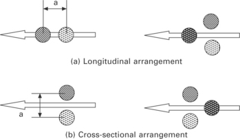
In laser keyhole welding, a number of defects, such as porosity, surfaces holes or pits, undercuts, humping and solidification cracking are frequently observed which deteriorates the quality of the welded parts.20–23 Some researchers65,66 believe these welding defects are related to the keyhole instabilities during the laser welding process. In order to overcome these defects to make high-quality and consistent laser welds, in recent years, a new welding technique combining two or more laser beam sources, called dual-/ multiple-beam laser welding, has been proposed and is under development to become an enabling joining technique.65–72 Studies have demonstrated that this new laser welding technique can provide benefits over conventional single-beam laser welding, such as increasing keyhole stability, slowing down cooling rate, and delaying the humping onset to a higher welding speed. It was reported that dual-beam laser welding can significantly improve weld quality. As shown in Fig. 5.6, two or more laser beams can be integrated in either traverse or longitudinal or mixed traverse and longitudinal arrangement in dual-Imultiple-beam laser welding.
Although many experimental and numerical studies73–89have been conducted in recent years for single-beam laser beam welding processes, the investigations conducted for dual-/multiple-beam welding are limited. Most of the studies conducted to characterize the multi-spot laser welding process65–72are trial-and-error in nature. Xie65,66 found that use of dual-beam laser processing can delay humping onset to higher speeds and slow down cooling rates. He also observed, in his experiments, for dual-beam laser welding of steel, surface quality had been improved with fewer surface defects such as undercut, surface roughness, spatter, and underfill. Weld hardness and centerline cracking susceptibility had also been reduced. For dual-beam laser welding of aluminum, quality improvements were in the form of smooth weld surfaces and fewer weld defects such as porosity, surface holes, and undercut. Through his experimental observations, Xie accredited the improved weld quality to better keyhole stability during the dual-beam laser welding process. Iwase et al.67 have found a larger keyhole during dual beam Nd:YAG laser welding via real-time X-ray observations. An elongated keyhole was found to be the reason that enables the vapor to escape from the keyhole freely and thus results in a stable welding process. Coste et al.68,69 found that deep penetration could be achieved up to 60 mm by combining two or three Nd:YAG lasers up to 12 kW. In the experiments conducted by Nakabayashi et al.,70 a deep penetration up to 20 mm with a welding speed of 1 m/min could be achieved by combining a system of a 6 kW Nd:YAG laser and a 10 kW chemical oxygen-iodine laser. Gref et al.71 experimentally studied the dual-beam laser welding process and concluded that the increased penetration depth is due to the improved energy coupling and process efficiency in the dual-beam welding process. They also pointed out that this efficiency is dependent on the configurations of two laser beam sources.
Although these experimental studies can provide some useful information on the dual-beam laser welding process, they cannot reveal the underlying physics of the process. For example, as shown in the experimental studies of Fabbro90 and Coste et al.,68,69 the shape of the weld pool in dual-beam welding is different from that observed for a single-beam welding. However, this difference cannot be well explained without the knowledge of weld pool dynamics during the welding process. Mathematical models have been proposed to understand the transport phenomena in this new welding process. Unfortunately, these studies are very limited. Chen and Kannatey-Asibu91 studied the heat transfer during a conduction-mode dual beam laser welding process. Hou92 and Capello et al.93 simulated a welding process involving two laser beams as a system in which one beam served as a minor heat source and the other was a major heat source. The fluid flow was not considered in their models and the beam distance was much larger than the beam size. Hu and Tsai94 simulated a stationary 3D dual-beam laser welding process; however, the keyhole plasma was not considered in the model.
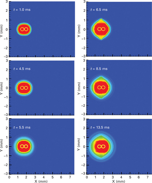
Recently, Zhou et al.73,74 extend their modeling work in a 3D moving single-beam laser welding process to investigate the heat transfer and fluid flow in the weld pool, the evolutions of two keyholes and their interaction in a 3D dual-beam laser welding process. As shown in Plate V (between pages 328 and 329), they found that the interaction of two keyholes caused the strong fluid flow in the direction perpendicular to the connection line of the two laser beam centers, leading to the oval-circle-oval shape change of the weld pool in the dual-beam welding process, as observed in some experiments.90 Their study also clearly showed the meltdown and disappearance process of the liquid metal in the middle of the beam centers, which indicates that the process is greatly dependent on the distance between the two beam centers. Also, it was found that a large keyhole with a big weld pool in the rear of the keyhole was very helpful in improving the keyhole stability and delaying the cooling process and, hence, suppressing the humping.
5.3.3 Pulse control in laser welding for porosity prevention
Based on the studies of porosity formation mechanisms, in pulsed laser welding, controlling the laser pulse duration and power density has been proposed to delay the solidification process and increase the backfilling time laser welding, thus to prevent/eliminate porosity formation in laser welds.
Plate VI (between pages 328 and 329) shows the effect of pulse control on keyhole collapse and metal solidification in a medium depth-to-width ratio keyhole laser welding process.19 As shown, when the main laser power is removed, the keyhole begins to collapse. However, with the pulse control, the laser is not completely shut down. Instead, the laser is still kept on for a while at a reduced power level. This reduced laser power helps to continue to heat the keyhole surface, which allows liquid metal at the bottom of the keyhole to remain as liquid for a while. As the liquid metal from the shoulder of the keyhole flows toward the center, it prevents part of the laser light from reaching the bottom surface of the keyhole, which leads to a temperature decrease on this part of the keyhole wall. However, the multiple reflections on the keyhole wall reflect some laser energy to the keyhole wall where laser light cannot radiate directly. This helps to delay the solidification process along the keyhole wall. When the keyhole is almost completely closed from the top, only a very small portion of the laser light can reach the bottom of the keyhole. However, the temperature on the bottom of the keyhole wall is still hot enough to allow the metal to stay liquid. At this time, most of the laser energy is used to heat the liquid metal on the top, which facilitates the liquid metal on the top to flow downward, as the downward momentum of the liquid metal is strong. Hence, within a short period of time, the downward flowing liquid metal almost completely fills up the keyhole and no pores will be found in the final welds. Although some gas is enclosed, the gas is surrounded by liquid metal, which can continue to flow into the gas region. During the backfilling process, the hydrostatic pressure continues to accelerate the melt flow, which facilitates the backfilling process. The downward flowing liquid metal makes the gas region smaller and smaller. In addition, since the gas is a mixture of shielding gas and metal vapor, some of it will be dissolved in the liquid metal during the compression process and eventually the gas region will disappear in the metal liquid, which is observed by Katayama and Matsunawa.22
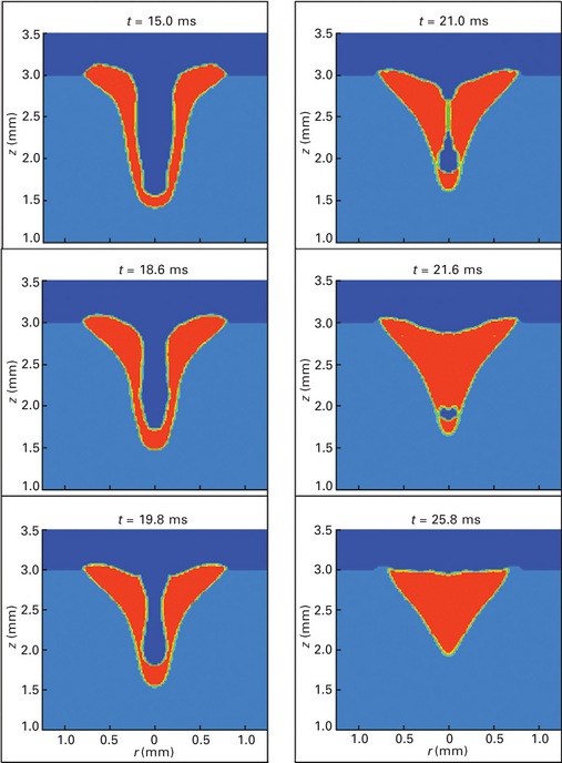
Plate VI Keyhole collapse and porosity elimination in a medium depth-to-width ratio keyhole laser welding with pulse control.
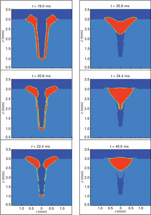
The effectiveness of pulse control has also been investigated on a large depth-to-width ratio keyhole laser welding process. As shown in Plate VII (between pages 328 and 329) due to the additional heat input after the removal of the main laser power, the hot plasma tends to keep the liquid metal on the bottom of the keyhole and delay the solidification process of the liquid metal on the side of the keyhole. However, since the keyhole aspect ratio is larger in this case, more liquid metal is located on the shoulder, which leaves a larger crater on the top of the keyhole. Meanwhile, the reduced laser energy can keep the temperature of the liquid metal on the top high, which facilitates the melt flow there. Hence, after the removal of the main laser power, with the action of surface tension force and hydrostatic pressure, this large crater will drive the hot liquid metal on the top to move inward more quickly to close the keyhole and shorten the time for keyhole closure. When the liquid metal from the shoulder of the keyhole approaches the keyhole center, the amount of laser beam energy entering the keyhole becomes smaller and smaller. Although the multiple reflections can still bring some laser light to heat the keyhole wall where the laser light cannot radiate directly, the total area is relatively large compared with that in a medium aspect ratio keyhole, the heat input per unit area is reduced for a high aspect ratio keyhole. This facilitates the solidification process on the keyhole wall and bottom. As shown, since the keyhole collapsed and closed on the top very quickly, laser light cannot enter the keyhole after the close of the keyhole top and the liquid metal on the bottom of the keyhole quickly solidifies. Although, with the action of hydrostatic pressure, the liquid metal on the upper and middle part of the keyhole flows downward to fill the keyhole, due to the fast solidification rate, the bottom part of the downward flowing liquid metal completely solidifies before it can reach the keyhole bottom. After that, no liquid metal can reach the bottom of the keyhole and a pore/ void is still found at the root of the keyhole. However, there is no pore or void found in the upper part of the keyhole.
5.3.4 Laser welding with electromagnetic force assistance
As discussed above, controlling the pulse shape of the laser irradiation was proposed to delay the solidification process, thus to reduce/eliminate the porosity formation in laser welding.19 This method prolongs the solidification rate and has been demonstrated to be effective in preventing/eliminating porosity for a medium depth-to-width ratio keyhole laser welding process. However, it failed for a keyhole with large depth-to-width ratio. In recent years, a new method is proposed aiming to control the backfilling melt flow during the keyhole collapse process, thus to reduce/eliminate the porosity formation in laser welding.95 This has been achieved by increasing the backfilling speed of the molten metal via the application of an electromagnetic force (Lorentz force) in laser welding. Electromagnetic force has been found to be able to affect melting and solidification processes.96–98 It has been used in arc welding to change flow conditions.99–102 In arc welding, when an electric current flows through the workpiece, it interacts with a self-introduced magnetic field, generating an electromagnetic force. This electromagnetic force can change the momentum of the melt flow and avoid weld slag or droplet detachment under the effect of gravitation when welding in a ‘wall position’.99,100 In gas metal arc welding, temperature and velocity evolutions, weld pool geometry and thermal cycles were also observed to be strongly influenced by electromagnetic force.101,102 Recently, experimental studies have been conducted to investigate the usage of electromagnetic force in laser welding.103,104Electromagnetic force was found to be able to affect the melt flow and weld pool dynamics in laser welding to achieve good quality welds.
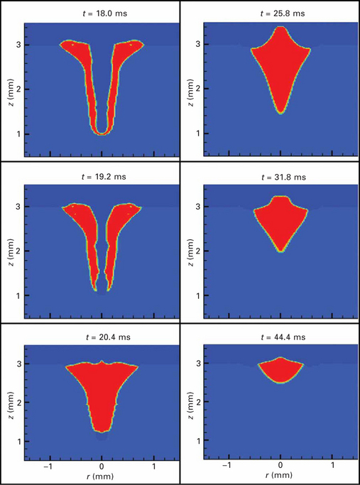
Plate VIII (between pages 328 and 329) shows the effectiveness of using electromagnetic forces on the prevention of porosity formation in laser welding.95 As shown, an external current of 30 A and a constant magnetic flux Bθ = 300 mT are applied as soon as the laser irradiation is shut off and they last for 5 ms. As shown, after the laser power is shut off, the recoil pressure is gone and the liquid metal near the top of the keyhole has a tendency to flow downward to fill the keyhole under the action of gravity and surface tension. As the electromagnetic force is downward and inward, it enhances the gravitational force and surface tension and shortens the time for the liquid metal to backfill the keyhole. As shown in Fig. 5.7, between t = 15.0 ms and 15.6 ms, the downward and inward velocities of the melt flow in the keyhole change more quickly than those without electromagnetic force. This is especially true for the liquid metal near the shoulder of the keyhole; the inward electromagnetic force ‘sweeps’ the molten metal surrounding the top of the keyhole into the keyhole. Thus, the keyhole is filled earlier with the applied electromagnetic force. As shown, the liquid–solid interface (i.e., solidification front) moves inward and upward from the keyhole in the metal after the laser irradiation is terminated. As the electromagnetic force is greater near the top of the keyhole and much less liquid metal exists near the bottom of the keyhole than that on the shoulder, the effect of electromagnetic force on the liquid metal near the bottom is not as remarkable as on that near the top of the keyhole. Hence, the application of electromagnetic force has little influence on the solidification rate of the liquid metal near the bottom of the keyhole. However, the downward velocity of liquid metal continues to be accelerated by electromagnetic force and the bottom of the keyhole at t = 20.4 ms is filled before complete solidification. Hence, there is no pore/ void formed in the final weld.
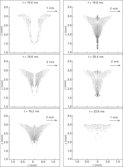
5.7 The corresponding velocity evolutions in weld pool as shown in Plate VIII.
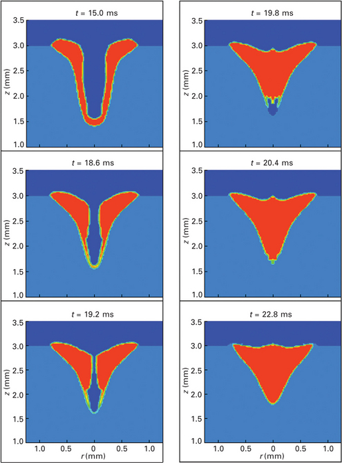
Plate VIII Effect of external electromagnetic force on keyhole collapse and porosity prevention in a medium depth-to-width ratio keyhole laser welding process.
As discussed above, since the formation of porosity in laser welding is strongly related to the depth-to-width ratio of the keyhole,19 the larger the ratio, the more likely the porosity is easy to form. In order to prevent the porosity at the root of the keyhole in a large depth-to-width ratio laser keyhole welding process, the backfilling speed of the liquid metal must be accelerated faster than that in the medium ratio keyhole laser welding process. The effects of the strength of electromagnetic force and its duration on melt flow and porosity formation will be discussed in the following. In the following discussions, the electric current used in these study cases are all at 30 A, while the magnitude and duration of the external magnetic flux vary. Based on the relative magnitude of the magnetic flux, in the following discussions, small, medium, and large electromagnetic force will be used.
As shown in Plate IX (between pages 328 and 329), when a small electromagnetic force is applied, the liquid metal on the top flows inwards and downwards to quickly refill the keyhole after the laser beam is shut off. In this case, the keyhole is deeper, which means it requires a longer time for the liquid metal from the top to reach the bottom of the keyhole. Since the magnitude of the electromagnetic force is relatively small, the liquid metal could not be accelerated fast enough to reach the bottom of the keyhole before its complete solidification. As shown, the bottom of the backfilling liquid metal solidifies at the depth of about 1.6 mm. After that, although there is still some liquid metal on the top, it was blocked by the solidified metal and could not flow farther to reach the bottom of the keyhole. Hence, a pore/ void was found at the root of the keyhole, though the size of the pore/void is smaller than that in laser welding without using electromagnetic force.
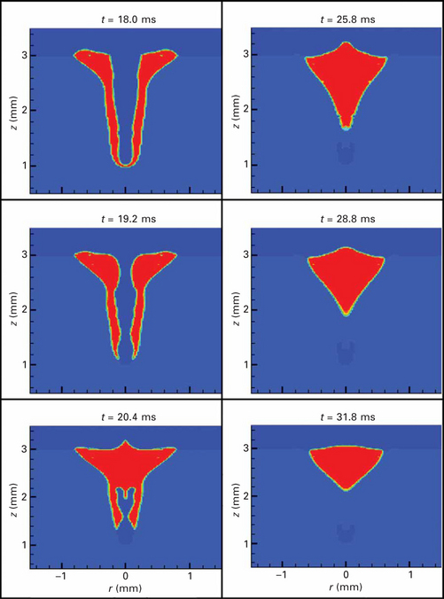
Plate IX Effect of applying a small electromagnetic force on porosity prevention in a large depth-to-width ratio keyhole laser welding process.
A medium magnetic force is then applied with the magnetic flux Bθ increased to 300 mT and the duration of the magnetic field is 5.0 ms. Since the magnitude of the applied electromagnetic force is higher, the backfilling speed of the liquid metal from the top is faster. Due to the strong downward momentum induced by the downward electromagnetic force, the liquid metal on the top quickly flows downwards and reaches the bottom of the keyhole before complete solidification. Then, the keyhole was completely filled up by the liquid metal and the pore/void at the root of the keyhole was eliminated. A small extrusion was found in the center of the weld pool. This is due to the strong inward push of the liquid metal by the electromagnetic force. However, under the action of the hydrostatic force and surface tension, this squeezed liquid metal is able to flow back to the edge of the keyhole before complete solidification. Plate X (between pages 328 and 329) shows the effect of using a large electromagnetic force on porosity prevention. As shown, the magnetic flux Bθ is now increased to an even higher level at 400 mT. Since the magnitude of electromagnetic force is greater at t = 19.2 ms, the downward velocity of the liquid metal is greater. This strong electromagnetic force pushes the liquid metal from the top to flow downwards to fill up the keyhole much faster than those in the previous two cases. As shown, the liquid metal from the top almost completely fills up the keyhole in a very short time period. Hence, the pore/void at the bottom of the keyhole caused by rapid solidification after the shut-off of the laser power is eliminated. Although this large electromagnetic force can help prevent porosity formation at the root of the keyhole more easily, it can cause some other welding defects. As shown in Fig. 5.8, the inward velocity of the liquid metal becomes very strong due to the strong inward push from this large electromagnetic force that squeezes the liquid metal to move upwards. Even though the electromagnetic force is turned off at t = 21.0 ms, since the upward momentum of the liquid metal is so strong, it takes a relatively longer time for the hydrostatic force and surface tension to even the liquid metal. At this time, since the solidification proceeds quite quickly, the liquid metal flowing from the center toward the edge quickly solidifies. Undercuts at the edge of the final weld are clearly found as well as an extrusion in the center of the final weld. Hence, laser welding with electromagnetic force assistance must be optimized to achieve quality welds.
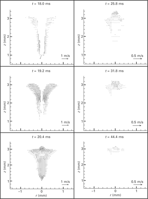
5.8 The corresponding velocity distributions in weld pool as shown in Plate X.
5.4 Future trends
Thanks to the improved understanding of the process, developments in laser source and process technology, the use of laser welding in industries has experienced tremendous growth over the last decade.2 This will continuously be the trend to further develop and advance the laser welding technology in the future. Developments in laser source include the introduction of higherpower Nd:YAG lasers, utilizing diode pumped rods or disks, and fiber lasers, both providing the capability for fiber optic beam delivery. The use of higher power lasers with fiber optic beam delivery allows these systems to be easily integrated into manufacturing systems and provide dependable processing conditions. These systems will continue to gain attractiveness for a wide range of applications, with the potential for reduced operating costs and greater process capability. However, the application of these innovative sources will be related to advancements in process technology. A critical examination of the emerging laser process technology for welding must include the hybrid laser-arc welding processes, which are seeing considerable interest worldwide and are currently being evaluated for various applications within heavy industry and manufacturing.2
The benefit of the hybrid laser-arc process is the synergistic effect of improved processing rates and joint accommodation over either of the processes viewed separately. However, more studies need to be done to better understand the underlying physics in the process, such as keyhole plasma and laser plasma interaction. Other process technologies, such as the integration of dual or multiple laser beams in welding, are being developed to further improve the robustness of laser beam welding for industry. The most effective means of developing and implementing these advanced process techniques involves the use of improved process understanding refined through direct experimental observations and accurate theoretical simulations. Developments in mathematical modeling and numerical simulation techniques have provided and will continue to offer unprecedented opportunities to study the transient nature of the laser welding process. Accurate modeling of important phenomena in the welding process like laser-matter interaction, keyhole formation and dynamics, plasma formation, energy transport in plasma and metal; and their resultant effect on the weld quality will broaden the applications of laser welding in wider industries including shipbuilding, electronics, biology, automotive, oil and gas, and medicine. In the near future, laser welding will be continuously developed to become an enabling joining technology for assembling a broad range of materials like aluminum and magnesium alloys, plastics, biomaterials, dissimilar materials, etc., at both macro and micro scale.
5.5 References
1. Duley, W. Laser Welding. Chichester: John Wiley & Sons; 1999.
2. Martukanitz, R. A critical review of laser beam welding. Proceedings of SPIE. 2005; 5706:11–24.
3. Quintino, L., Costa, A., Miranda, R., Yapp, D., Kumar, V., Kong, C. J. Welding with high power fiber lasers – a preliminary study. Materials & Design. 2007; 28:1231–1237.
4. Zhou, J., Tsai, H. L. Modeling of transport phenomena in hybrid laser–MIG keyhole welding. International Journal of Heat and Mass Transfer. 2008; 51:4353–4366.
5. Page, C. J., Devermann, T., Biffin, J., Blundell, N. Plasma augmented laser welding and its applications. Science and Technology of Welding & Joining. 2002; 7(1):1–10.
6. Joo, S. M., Kim, Y. P., Ro, C. S., Bang, H. S., Park, J. U. Basic experiments by hybrid welding to steels for shipbuilding. Adv. Nondestr. Eval.. 2004; 270–273:2383–2388.
7. Graf, T., Staufer, H. Laser–hybrid welding drives VW improvements. Welding Journal. 2003; 82:42–48.
8. Ono, M., Shinbo, Y., Yoshitake, A., Ohmura, M., Welding properties of thin steel sheets by laser–arc hybrid welding: laser–focused arc welding. Proc. 1st Int. Symp. on ‘High–power laser microprocessing’, Osaka, Japan. 2002:369–374.
9. Song, G., Liu, L. M., Chi, M. S., Wang, J. F. Investigations of laser–TIG hybrid welding of magnesium alloys. Materials Science Forum. 2005; 488–489:371–375.
10. Chiang, K. C., Tsai, H. L. Shrinkage–induced fluid flow and domain change in two–dimensional alloy solidification. Int. J. Heat and Mass Transfer. 1992; 35:1763–1769.
11. Zhou, J., Tsai, H. L., Wang, P. C. Transport phenomena and keyhole dynamics during pulsed laser welding. ASME Journal of Heat Transfer. 2006; 128(7):680–690.
12. Anisimov, S. I. ‘Vaporization of metal absorbing laser radiation’, Soviet Physics. JETP. 1968; 27(1):182–183.
13. Knight, C. J. Theoretical modeling of rapid surface vaporization with back pressure. AIAA J. 1979; 17(5):519–523.
14. Kanouff, M. P., Kassinos, A., Noble, D. R., and Schunk, P. R., ‘Laser spot weld modeling using an ALE finite element method’, Sandia National Laboratories Report.
15. Kaplan, A. A model of deep penetration laser welding based in calculation of the keyhole profile. J. Phys. D: Appl. Phys.. 1994; 27:1805–1814.
16. Duley, W. Laser Welding. Chichester: John Wiley & Sons; 1999.
17. Ducharme, R., Williams, K., Kapadia, P., Dowden, J., Steen, B., Glowacki, M. The laser welding of thin metal sheets: an integrated keyhole and weld pool model with supporting experiments. J. Phys. D: Appl. Phys.. 1994; 27:1619–1627.
18. Ho, J. R., Grigoropoulos, C. P., Humphrey, J. A. C. Gas dynamics and radiation heat transfer in the vapor plume produced by pulsed laser irradiation of aluminum. J. Appl. Phys.. 1996; 79:7205–7215.
19. Zhou, J., Tsai, H. L. Porosity formation and prevention in pulsed laser welding. ASME Journal of Heat Transfer. 2007; 129:1014–1024.
20. Ishide, T., Tsubota, S., Nayama, M., Shimokusu, Y., Nagashima, T., Okimura, K. 10 kW class YAG laser application for heavy components. Osaka. SPIE High–Power Lasers in Manufacturing. 1999; 3888:543–550.
21. Katayama, S., Seto, N., Kim, J., Matsunawa, A., Formation mechanism and reduction method of porosity in laser Welding of stainless steel Sec. G,. Proceedings of ICALEO. 1997:83–92.
22. Katayama, S., Matsunawa, A. Formation mechanism and prevention of defects in laser welding of aluminum alloys. Proceedings of CISFFEL. 1998; 6:215–222.
23. Katayama, S., Seto, N., Kim, J., Matsunawa, A., Formation mechanism and suppression procedure of porosity in high power laser welding of aluminum alloys Sec. C. Proceedings of ICALEO. 1998:24–33.
24. Katayama, S., Seto, N., Mizutani, M., Matsunawa, A., Formation mechanism of porosity in high power YAG laser welding Sec. C. Proceedings of ICALEO. 2000:16–25.
25. Seto, N., Katayama, S., Matsunawa, A., A high–speed simultaneous observation of plasma and keyhole behavior during high power CO2 laser welding Sec. E,. Proceedings of ICALEO. 1999:17–19.
26. Katayama, S., Kohsaka, S., Mizutani, M., Nishizawa, K., Matsunawa, A. Pulse shape optimization for defect prevention in pulsed laser welding of stainless steels. Proceedings of ICALEO. 1993; 487–497.
27. Tusek, J., Suban, M. Hybrid welding with arc and laser beam. Science and Technology of Welding and Joining. 1999; 4(5):308–311.
28. Mahrle, A., Beyer, E. Hybrid laser beam welding – classification, characteristics, and applications. Journal of Laser Applications. 2006; 18(3):169–180.
29. Casalino, G. Statistical analysis of MIG–laser CO2 hybrid welding of Al–Mg alloy. J. Mater. Process. Technol.. 2007; 191:106–110.
30. Hu, B., Richardson, I. M. Microstructure and mechanical properties of AA7075(T6) hybrid laser/GMA welds. Material Science Engineering A. 2007; 459:94–100.
31. Feng, Z. L. Processes and Mechanisms of Welding Residual Stress and Distortion. Cambridge: Woodhead Publishing; 2005.
32. Metzbower, E. A., Denney, P. E., Moon, D. W., Feng, C. R., Lambrakos, S. G. Thermal analysis and microharness mapping in hybrid laser welds in a structural steel. Materials Science Forum. 2003; 426–432:4147–4152.
33. Ribic, B., Palmer, T. A., Debroy, T. Problems and issues in laser–arc hybrid welding. International Materials Reviews. 2009; 54(4):223–244.
34. Song, G., Liu, L. M., Wang, P. C. Overlap welding of magnesium AZ318 sheets using laser–arc hybrid process. Material Science and Engineering A. 2006; 429:312–319.
35. Nonn, A., Dahl, W., Bleck, W. Numerical modelling of damage behaviour of laser–hybrid welds. Engineering Fracture Mechanics. 2008; 75:3251–3263.
36. Pinto, H., Pyzalla, A., Hackl, H., Bruckner, J. A comparative study of microstructure and residual stresses of CMT-, MIG- and laser-hybrid welds. Materials Science Forum. 2006; 524–525:627–632.
37. Zhang, J. X., Xue, Y., Gong, S. L. Residual welding stresses in laser beam and tungsten inert gas weldments of titanium alloy. Science and Technology of Welding & Joining. 2005; 10:643–646.
38. Liu, L. M., Song, G., Wang, J. F. Investigations of laser–TIG hybrid welding of magnesium alloys. Materials Science Forum. 2005; 488–489:361–364.
39. Liu, L. M., Song, G., Liang, G. L., Wang, J. F. Pore formation during hybrid laser tungsten inert gas arc welding of magnesium alloy AZ31B – mechanism and remedy. Material Science and Engineering A. 2005; 390:76–80.
40. Katayama, S., Uchiumi, S., Mizutani, M., Wang, J., Fujii, K. Penetration and porosity prevention mechanism in YAG laser–MIG hybrid welding. Welding International. 2007; 21:25–31.
41. Fellman, A., Kujanpaa, V. The effect of shielding gas composition on welding performance and weld properties in hybrid CO2 laser–gas metal arc welding of carbon manganese steel. Journal of Laser Applications. 2006; 18:12–20.
42. Kim, T., Suga, Y., Koike, T. Welding of thin steel plates by hybrid welding process combined TIG arc with YAG laser. JSME International Journal Series A. 2003; 46A:202–207.
43. Kim, Y. P., Alam, N., Bang, H. S. Observation of hybrid (cw Nd:YAG laser + MIG) welding phenomenon in AA5083 butt joints with different gap conditions. Science and Technology of Welding & Joining. 2006; 11(3):295–307.
44. Murakami, K., Mitooka, Y., Hino, M., Iogawa, H., Ono, H., Katayama, S. YAG laser–TIG hybrid welding of 800 MPa–class high tensile strength steel. J. Japn. Inst. Met.. 2006; 70:134–137.
45. Qin, G. L., Lei, Z., Lin, S. Y. Effects of Nd:YAG laser + pulsed MAG arc hybrid welding parameters on its weld shape. Science and Technology of Welding & Joining. 2007; 12(2):79–86.
46. Swanson, P. T., Page, C. J., Read, E., Wu, H. Z. Plasma augmented laser welding of 6 mm steel plate. Science and Technology of Welding & Joining. 2007; 12(2):153–160.
47. Steen, W. M. Arc–augmented laser processing of materials. J. Appl. Phys.. 1980; 51:5636–5641.
48. Eboo, M., Steen, W. M., Clarke, J., Arc–augmented laser welding. Proc. 4th Int. Conf., Harrogate, UK. Advances in Welding Processes. 1978:257–265.
49. Steen, W. M., Eboo, M. Arc augmented laser welding. Metal Construction. 1979; 11:332–335.
50. Bagger, C., Olson, F. O. Review of laser hybrid welding. Journal of Laser Applications. 2005; 17(1):2–14.
51. Cui, H., Decker, I., Ruge, J., Wechselwirkungen zwischen WIGSchweißlichtbogen und fokussiertem Laserstrahl. Proc. of the Conference Laser’89, Springer, Berlin. 1989:577–581.
52. Finke, B. R., Stern, F., Decker, I. Auswirkungen eines unterstützenden Laserstrahls auf den WIG–Schweißprozess. DVS-Ber.. 1991; 135:149–152.
53. Cui, H., Decker, I., Pursch, H., Ruge, J., Wendelstorf, J., Wohlfahrt, H. Laserinduziertes Fokussieren des WIG-Lichtbogens. DVS-Ber.. 1992; 146:139–143.
54. Dilthey, U., Lüder, F., Wieschemann, A. Expanded capabilities in the welding of aluminium alloys with the laser–MIG hybrid process. Aluminium. 1999; 75:64–75.
55. Graf, T., Staufer, H., Laser hybrid process at Volkswagen. International Institute of Welding. 1999. [IIW–Doc. XII–1730–02].
56. Jokinen, T., Vihervä, T., Riikonen, H., Kujanpaä, V. Welding of ship structural steel A36 using a Nd:YAG laser and gas metal arc welding. Journal of Laser Applications. 2000; 12:185–188.
57. Höfemann, M., Fersini, M., Szinyur, J., Haferkamp, H., Cordini, P. Laser-GMA-hybrid welding of zinc-coated steel for hydroforming applications. Proc. 1st Int. WLT-Conf. on Lasers in Manufacturing, Munich, Germany. 2001:466–472.
58. Dilthey, U., Keller, H., Prospects in laser GMA hybrid welding of steel. Proc. 1st Int. WLT–Conf. on Lasers in Manufacturing, Munich, Germany. 2001:453–465.
59. Waltz, C., Seefeld, T., Sepold, G., Laser–GMA welding and its influence on bead geometry and process stability. Proc. 1st Int. WLT–Conf. on Lasers in Manufacturing, Munich, Germany. 2001:444–452.
60. Shibata, K., Sakamoto, H., Iwase, T., Laser-MIG hybrid welding of aluminium alloys. Proc. 1st Int. WLT-Conf. on Lasers in Manufacturing, Munich, Germany. 2001:436–443.
61. Jokinen, T., Jernström, P., Karhu, M., Vanttaja, I., Kujanpää, V., Optimisation of parameters in hybrid welding of aluminium alloy Proc. SPIE 4831. Proc. 1st Int. Symp. on High Power Laser Macroprocessing. 2003:307–312.
62. Ishide, T., Tsubota, S., Watanabe, M., Latest MIG, TIG Arc–YAG laser hybrid welding systems for various welding products Proc. SPIE 4831. Proc. 1st Int. Symp. on High Power Laser Macroprocessing. 2003:347–352.
63. Hyatt, C. V., Magee, K. H., Porter, J. F., Merchant, V. E., Matthews, J. R. Laser-assisted gas metal arc welding of 25–mm–thick HY–80 plate. Miami, FL: Welding Journal Symposium; 2001. [163 s–172 s].
64. Fellman, A., Jernstrøm, P., Kujanpä, V., The effect of shielding gas composition in hybrid welding of carbon steel. Proceedings 9th NOLAMP, Conference on Laser Materials Processing in the Nordic Countries, Trondheim, Norway. 2003:103–112.
65. Xie, J. Weld morphology and thermal modeling in dual–beam laser welding. Welding Journal. 2002; 283–290.
66. Dual beam laser welding. Welding Journal. 223s–230s, 2002.
67. Iwase, T., Shibata, K., Sakamoto, H., Dausinger, F., Hohenberger, B., Muller, M., Matsunawa, A., Seto, N. ICALEO 2000, Section C, pp. 26–34. Real time X-ray observation of dual focus beam welding of aluminum alloys. 2000.
68. Coste, F., Janin, F., Jones, L., Fabbro, V. Laser welding using Nd:Yag lasers up to 12 kW application to high thickness welding. ICALEO. 2002; 131–137.
69. Coste, F., Janin, F., Hamadou, M., Fabbro, R. Deep penetration laser welding with Nd:Yag lasers combination up to 11 kW laser power. LAMP. 2002; 46–53.
70. Nakabayashi, T., Wani, F., Okado, H., Hayakawa, A., Suzuki, S., Yasuda, K. ICALEO 2001, Section A. Laser welding characteristics with high power combing beam. 2001. [22–26].
71. Gref, W., Hohenberger, N., Dausinger, F., Hugel, H. Energy coupling and process efficiency in double–focus welding with Nd:YAG. ICALEO. 2002; 202–206.
72. Grupp, M, Seefeld, T, Sepold, G. Laser beam welding of aluminum alloys with diode pumped Nd:YAG lasers. ICALEO. 2001; 115–122.
73. Zhou, J. Modeling of three–dimensional laser welding process. University of Missouri–Rolla; 2003. [PhD dissertation].
74. Zhou, J., Zhang, W. H., Tsai, H. L., Marin, S. P., Wang, P. C., Menassa, R., Modeling the transport phenomena during hybrid laser-MIG welding process. IMECE’03, Washington, DC, November 16– 2003; 21:.
75. Semak, V. V., Hopkins, J. A., McCay, M. H., McCay, T. D. ICALEO 1994, 641–650. A concept for a hydrodynamic model of keyhole formation and support during laser welding. 1994.
76. Semak, V. V., Hopkins, J. A., McCay, M. H., McCay, T. D. ICALEO 1994 17–20. Dynamics of penetration depth during laser welding. 1994.
77. Klemens, P. G. Heat balance and flow conditions for electron beam and laser welding. J. Appl. Phys.. 1976; 47:2165–2174.
78. Allmen, M., Blatter, A. Laser-Beam Interaction with Material, 2. Berlin, Heidelberg: Springer–Verlag, 1995.
79. Solana, P., Kapadia, P., Dowden, J. ICALEO 1998, Sec. F 142–147. Surface depression and ablation for a weld pool in material processing: a mathematical model. 1998.
80. Clucas, A., Ducharme, R., Kapadia, P., Dowden, J., Steen, W. ICALEO 1998, Sec. F 123–131. A mathematical model of laser keyhole welding using a pressure and energy balance at the keyhole walls. 1998.
81. Matsunawa, A., Kim, J., Seto, N., Mizutani, M., Katayama, S. Dynamic of keyhole and molten pool in laser welding. J. Laser Appl.. 1998; 10:247–254.
82. Chen, M. M., Bos, J. A., Melt flow in deep penetration welding Sec. F. ICALEO 1998 187–196. 1998.
83. Ducharme, R., Williams, K., Kapadia, P., Dowden, J., Steen, B., Glowacki, M. The laser welding of thin metal sheets: an integrated keyhole and weld pool model with supporting experiments. J. Phys. D: Appl. Phys.. 1994; 27:1619–1627.
84. Sudnik, R., Rada, D., Breitschwerdt, S., Erofeew, W. Numerical simulation of weld pool geometry in laser beam welding. J. Phys. D: Appl. Phys.. 2000; 33:662–671.
85. Kapadia, P., Dowden, J., Ducharme, R. ICALEO 1996, Sec. B, 106–114. A mathematical model of ablation in the keyhole and droplet formation in the plume in deep penetration laser welding. 1996.
86. Farson, D. F., Kim, K. R. ICALEO 1998, Sec. F 197–206. Simulation of laser evaporation and plume. 1998.
87. Miyamoto, I., Ohmura, E., Maede, T. ICALEO 1997, Sec. G 210–218. Dynamic behavior of plume and keyhole in CO2 laser welding. 1997.
88. Solana, P., Negro, G. A study of the effect of multiple reflections on the shape of the keyhole in the laser processing of material. J. Phys. D: Appl. Phys.. 1997; 30:3216–3222.
89. Metzbower, E. A., Absorption in the keyhole Sec. G. ICALEO 1997 16–25. 1997.
90. Fabbro, R., ‘Basic processes in deep penetration laser welding’, ICALEO 2002, 182–187.
91. Chen, T. C., Kannatey-Asibu, E., Jr. Convection pattern and weld pool shape during conduction–mode dual beam laser welding. Proceedings of 24th North American Manufacturing Research Conference, Ann Arbor, MI. 1994:259–264.
92. Hou, C. A. IASTE, Pittsburgh, PA 430–433. Finite element simulation of dual-beam laser welding using ANSYS. 1994.
93. Capello, E., Chiarello, P., Piccione, E., Previtali, B., Analysis of high power CO2 dual beam laser welding. Advanced manufacturing systems and technology No. 437. Courses and Lectures – International Center for Mechanical Sciences. 2002.
94. Hu, J., and Tsai, H. L., ‘Fluid flow and weld pool dynamics in dual–beam laser keyhole welding’, Proceeding of IMECE’03, 353–360.
95. Zhou, J., Tsai, H. L. Effects of electromagnetic force on melt flow and porosity prevention in pulsed laser keyhole welding. International Journal of Heat and Mass Transfer. 2007; 50:2217–2235.
96. Sampath, R., Zabaras, N. A joint variable method for the thermal design of eutectic directional solidification processes in an open–boat configuration. Numer. Heat Transfer Part A: Appl.. 2001; 32(6):655–683.
97. Goncalves, E., Faghri, M., Asako, Y., Charmchi, M. Numerical solution of melting processes for unfixed phase–change material in the presence of electromagnetically simulated low gravity. Numer. Heat Transfer Part A: Appl.. 2004; 46(4):343–365.
98. Goncalves, E., Faghri, M., Asako, Y., Charmchi, M. Numerical solution of melting in side–heated rectangular enclosure under electromagnetically simulated low gravity. Numer. Heat Transfer Part A: Appl.. 2005; 47(4):315–332.
99. Manabe, Y., Wada, H., Kondou, H., Hiromoto, Y., Kobayashi, Y., Development of new GTAW process by magnetic control on molten pool. International Institute of Welding, IIW–XII. 1997:1484–1497.
100. Shelenkov, G. M. Special features of the formation of joints in the arc welding of titanium with electromagnetic stirring. Weld. Production. 1997; 3:24–25.
101. Kou, S., Wang, Y. H. Computer simulation of convection in moving arc weld pools. Metall. Trans.. 1986; 17A:2271–2277.
102. Kim, W. H., Fang, H. G., Na, S. J. Effect of various driving forces on heat and mass transfer in arc welding. Numer. Heat Transfer Part A: Appl.. 1997; 32(6):633–652.
103. Kern, M., Berger, P., Hugel, H. Magneto–fluid dynamic control of seam quality in CO2 laser beam welding. Weld. J.. 2000; 79(3):72s–78s.
104. Lindenau, D., Ambrosy, G., Berger, P., Hugel, H. Effects of magnetically supported laser beam welding of aluminum alloys. ICALEO, Sec. A. 2001; 308–318.

