Applications of laser welding in the railway industry
Abstract:
With so many advantages, such as lightweight, antirust, low cost of maintenance and simple manufacturing process, the production of high-level stainless steel railway vehicles has become the development strategy of European, American and other developed nations. High-quality surface state and structure strength can be achieved by the partial penetration lap laser welding of the side panel structure. Laser welding will be the new technology for the manufacture of railway vehicles. The laser welding process, influence of laser welding parameters on the surface and strength, the heat source model of lap laser welding, methods of quality control, and future trends in laser welding are discussed in this chapter.
22.1 Introduction: the role of laser welding in railway engineering
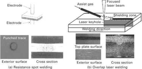
Stainless steel railway vehicles have many advantages such as lightweight body structure, high anti-corrosion, safety features, good environmental performance, etc. SUS301L is one of the most widely applied materials in the stainless steel vehicle structure on unpainted outside panels [1]. Because of its low thermal conductivity and large linear expansion coefficient, stainless steel is usually assembled with resistance spot welding (RSW). But due to the punched power and thermal input of resistance of the spot welding electrode, there will be a visible indentation 1 cm in diameter left on the surface of the stainless steel vehicle body, influencing the appearance quality and airtightness. It is necessary and urgent to find a new method to resolve these issues.
Recently, high power density welding processes have been increasingly used in industrial manufacturing, because of their enormous advantages, such as minor shape distortions, reduction of size of heat-affected zone (HAZ), and faster welding speed associated with high penetration [2]. Some studies [3,4] have investigated the possibility of applying laser technology to replace resistance spot welding for stiffener assembly on rail vehicle side panels. Japanese Kawasaki Heavy Industries have studied the method of lap laser welding of SUS304 stainless steel with no visible indentation on the outside surface, which was reported in Ref. [3]. The author also pointed out the problems discussed above and summarized the resistance spot welding joint as ‘point’ connections, and the laser welding joint as ‘line’ connections. Some experiments [5,6] indicated that the welding speed should match the laser power, namely high welding speed matching high laser power, to get a joint with no visible indentation on the surface. Various studies have indicated that the welding speed could be up to 5 m/min, which was too high for ordinary lasers [3,4].
In addition, laser welding technology will be applied to Siemens magnetic levitation train in Germany, DMU IC4 level high-speed train in Denmark, ETR500 high-speed commuter trains in Italy, and so on.
22.2 Laser welding technology for stainless steel railway vehicles
The disk laser is a brilliant combination of a solid-state laser and a diode laser. The diode laser provides a high degree of pumping efficiency and the solid-state laser, as a disk laser, provides the high beam quality [7]. The optimized combination of high laser power plus excellent beam quality is kept constant across the entire power range. YAG laser beam welding with a continuous wave is a high energy density and low heat input process. The result is a small HAZ, which cools very rapidly with very little distortion, and a high depth-to-width ratio for the fusion zone [8].
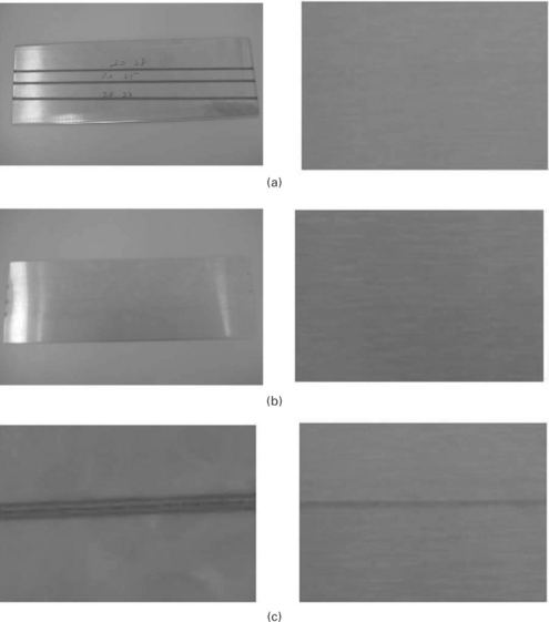
SUS301L is a kind of austenitic stainless steel with reliable structural strength. Because of its light weight and environment protection, SUS301L is widely applied in the stainless steel vehicle structure as the outside panel with no painting [9]. Due to deformation caused by the welding heat, the stainless steel is assembled with resistance spot welding with small thermal importation. But because of the punched power and thermal input of resistance of spot welding electrodes, there will be a 1 cm in diameter left indentation on the outside surface of the stainless steel vehicle body (Fig. 22.1(a)). This influences the appearance of public transport vehicles, and should not be ignored.
To laser weld SUS301L stainless steel to get an overlap joint with no welded traces on the outside surface (shown in Fig. 22.1(b)) and higher tensile strength than that of resistance spot welding is a new area of research and will be applied in railway vehicle manufacturing.
Ordinarily, laser beam welding involves many variables: laser power, welding speed, defocusing distance and type of shielding gas, any of which may have an important effect on heat flows and fluid flows in the weld pool. In turn, this will affect penetration depth, shape and microstructure of the weld fusion zone. Both the shape and microstructure of the fusion zone will have a considerable influence on the properties of the joints and the quality of the exterior surface.
22.2.1 Influence of laser welding parameters
Influence of laser power
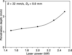
The influence of laser power was investigated, keeping both welding speed and defocusing distance constant at 22 mm/s and zero, respectively. The penetration depth increased sharply with increasing laser power from 1.5 to 2.5 kW as shown in Fig. 22.2.
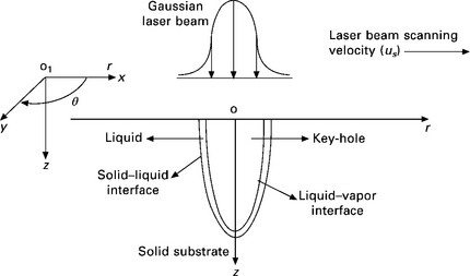
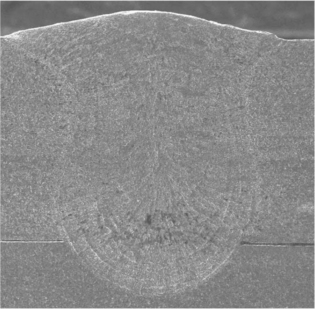
Figure 22.3 shows an example of a cross section of overlap weld joint using laser power of 2.0 kW. The microstructure of the cross section is shown with an inverted parabola shape, as the intensity of the laser beam has a Gaussian-like distribution (Fig. 22.4). The fusion zone is symmetrical about the axis of the laser beam. No welding cracks or pores (porosity) were found in any of the welds, and this may be partly due to the good crack resistance of the base metal and the welding conditions provided.
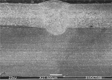
22.3 The microstructure of the cross section of overlap joint with the parameters P = 2.0 kW, v = 22 mm/s, Dd = 0 mm.
Mazumder and Steen [10] investigated a typical keyhole welding process model and the cylindrical coordinate system (r, θ, z) used in the model which is shown in Fig. 22.4. According to this model, the results also indicate that the development of the weld pool is essentially symmetrical about the axis of the laser beam. Laser power has less of an influence on both weld profile and HAZ width in comparison with its effect on penetration depth. This is in agreement with other researchers’ work, where they pointed out that changing laser power between 3 and 5 kW [11] did not result in any significant change in the size or shape of the weld.
When the laser power is lower than 2 kW and the penetration depth is below 1.4 mm, there are no welded traces on the exterior, but on the contrary distinct welded traces appear on the surface.
Influence of welding speed
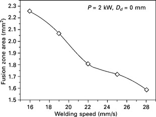
The influence of welding speed was investigated at the optimum laser power (2 kW) and zero defocusing distance. Figure 22.5 shows the relationship between welding speed and fusion zone area. The fusion zone area is defined as half of the product of depth and width of the fusion zone. The fusion zone area decreased sharply from 2.26 to 1.59 mm2 with the increase in welding speed from 16 to 28 mm/s.
The dependence of the fusion zone area on welding speed was confirmed at a different laser power (2.3 kW). A lower welding speed resulted in a considerable increase in the fusion zone area and consequently an increase in shear tensile strength of the overlap joint leading to unacceptable surface quality as shown in Fig. 22.6. When the weld speed is higher than 22 mm/s, there is no welded trace on the exterior surface. The shear tensile strength of the overlap joint at a speed of 25 mm/s is lower than that of the joint at a speed of 22 mm/s.
Influence of heat input
The influence of heat input as a function of laser power was clarified to be HI = P/S. The above results have shown that the laser power and welding speed should be optimized in order to minimize heat input and to obtain a satisfactory weld with reliable quality. This reflects one of the most notable features of laser welding compared with other welding processes, namely low heat input.
Turning to the macrographs shown in Figs 22.3 and 22.7, incomplete penetration and no welded trace on the exterior surface with higher shear tensile strength than that of RSW fusion zone profile could be obtained using either P = 2 kW, S = 22 mm/s (Fig. 22.7) or P = 2.3 kW, S = 25 mm/s (Fig. 22.11). However, P = 2 kW, S = 22 mm/s resulted in a smaller welded trace on the exterior surface. In laser welding, if the laser power is too high, the spatter will increase to pollute the focus lens, increasing the risk of lens explosion [12]. When achieving the same result, the lower laser power should be selected.
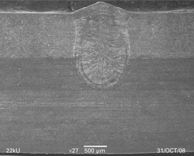
22.7 The microstructure of the cross section of overlap joint with the parameters P = 2.3 kW, v = 25 mm/s, Dd = 0 mm.
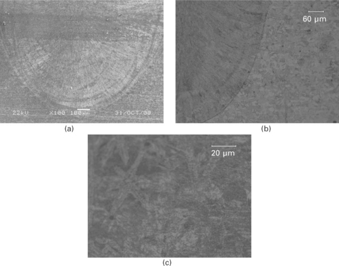
22.9 Microstructure of the overlap laser welding joint: (a) The microstructure of laser welding with parameters P = 2.0 kW, v = 22 mm/s, Dd = 0 mm; (b) the junction of weld seam and basement material with parameters P = 2.0 kW, v = 22 mm/s, Dd = 0 mm; (c) the equiaxes dendrites in the seam center with the parameters P = 2.0 kW, v = 22 mm/s, Dd = 0 mm.
Effect of defocusing distance
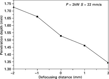
Defocusing distance is the distance between the specimen surface and the optical focal point. In order to study its influence on both penetration depth and surface quality, a lap joint was made by changing the defocusing distance between − 2 and 2 mm. Laser power (2 kW) and welding speed (22 mm/s) were selected to obtain incomplete penetration.
The relationship of the defocusing distance and the penetration of the overlap joint is shown in Fig. 22.8. The penetration depth is considerably decreased by changing the defocused distance from − 2 mm to 2 mm. In laser welding, when the focus is below the upper surface, the laser power density of the interior is higher than the surface, and the energy transfers deeper into the material, making it possible to weld thick materials with deep penetration. For thin materials, a positive focal position is usually used [13].
22.2.2 Features of laser welding joints in stainless steel railway vehicles
Microstructure of laser beam welds
In laser welding, the material is molten for a very short period and solidifies quickly, resulting in the difference between the microstructure of the laser welding and that of conventional welding methods. Molten metal first crystallized in the solid–liquid interface then grows up rapidly to the interior of the molten zone. The crystallized form in the fusion line extends to the center of the weld seam and finally combines there, and almost no HAZ can be seen as demonstrated in Fig. 22.9(a). No cracking or porosity was observed.
A clear dividing line marking the boundary of the fusion zone can be seen in the microstructure of the transition from the base material to the fusion zone (Fig. 22.9(b)). With the great degree of subcooling existing in the solid–liquid interface, the crystal of the fusion line grows upwards into columnar dentrites with rapid crystallization speed and distributed in parallel perpendicular to the fusion line. In the weld seam center, the gradient of temperature is smaller than that of its surroundings and the unfused suspended particle becomes the solidification surface of non-spontaneous nucleation, growing up freely from the cooling conditions into equiaxed dendrites (Fig. 22.9(c)). The equiaxed grains of the center were fine and shaped during the re-crystallization of the welding heat circulation.
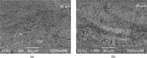
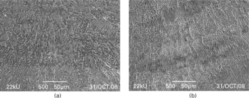
Microstructures of type SUS301L steel weld metals made using two different welding speeds, 19 and 22 mm/s, with the same laser power, 2 kW, are shown in Fig. 22.10(a) and (b), respectively. The noticeable feature is the highly directional nature of the microstructure around the axis of the laser beam. This is due to solidification of the weld metal at high cooling rate compared with that of conventional GTA welding [14].
It can also be noticed that the higher the welding speed, the finer the dendritic structure (Fig. 22.10(b)). This is attributed to an increase in both solidification and cooling rates due to low heat input resulting from high welding speed. Concerning the effect of laser power, the higher the laser power, the coarser is the dendritic structure due to decreasing cooling rate. However, the effect of laser power was relatively smaller than that of welding speed.
Mechanical properties
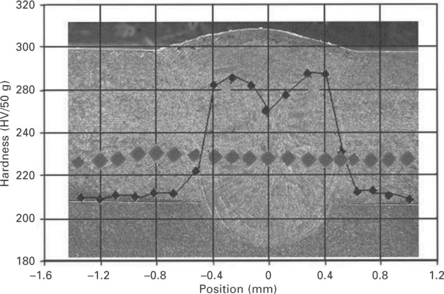
Shear tensile test results of all type 301 L laser lap welds with incomplete penetration showed that failure took place in the weld metal. Vickers hardness measurements with a 50 g loading force were carried out on the laser welding seams produced with different parameters. Figure 22.11 shows a cross section of a laser lap welded joint with the diagram of hardness. As expected, the hardness of the weld seam is higher than that of the base material. But the hardness of the weld seam center is lower than that of the part between the center and the fusion line.
The cooling rate of the weld seam center is more moderate than that of its surrounding part, and equiaxed dendrites appear in the center in the form of polygonal ferrite (PF) (as shown in Fig. 22.12(a)). In the zone between the fusion line and the weld seam center, the cooling rate is rapid and columnar dentrites appear there in the form of acicular ferrite (AF) (as shown in Fig. 22.12(b)). Between the two adjacent acicular ferrite (AF), there is martensite (M-A constituent as the main element). The cementite or martensite and the acicular ferrite (AF) have higher hardness than polygonal ferrite (PF), explaining the lower hardness in the weld seam center.
22.3 Heat source model of lap laser welding of stainless steel vehicles
22.3.1 Model and mesh
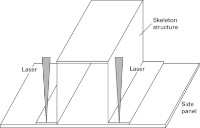
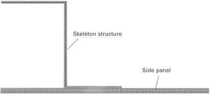
The physical model of a stainless steel vehicle side panel is shown in Fig. 22.13. According to the features of the side structure, the side part is symmetrical. So half of the physical model is taken as the finite element model in the simulation, as shown in Fig. 22.14. Since the laser energy density is high, the mesh near the weld is smaller, and in order to reduce the computational cost, the mesh size increases gradually relatively far away from the seam.
22.3.2 Boundary conditions
The initial temperature of the material is 20 °C. Taking into account the laser heating, the welding surface convection and radiation heat transfer [15] are shown by:
where Ts is surface temperature, Text is the ambient temperature, h is the convective heat transfer, σ is the Stefan-Boltzmann constant, and ε is the thermal radiation coefficient [16].
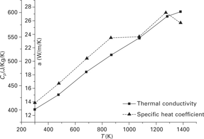
SUS301L is much used in stainless steel car body material. Thermal conductivity and the specific heat coefficient of SUS301L are shown in Fig. 22.15 and other parameters are listed in Table 22.1.
22.3.3 Selecting a heat source model
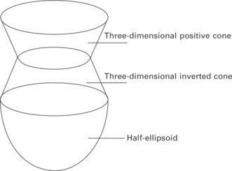
Figure 22.16 shows the microstructure of the weld of partial lap laser welding of stainless steel. According to the shape of the weld, the heat source model is selected. The combination of three-dimensional positive cone + three-dimensional inverted cone + half-ellipsoid heat source model is shown in Fig. 22.17 The upper and central parts of the heat source model are two three-dimensional cones. The lower part is ellipsoid heat source. The three-dimensional cone heat model is actually a series of flat plate Gaussian heat sources superimposed along the thickness. After calculation, the energy distribution rate of the three heat source models is 0.25:0.3:0.45.
The three-dimensional cone heat equations are shown below [17]:
In these equations, ze, zi are z coordinate positions where the heat source is working on the surface of the workpiece, and re, ri are the radii of the heat source distribution [18]. All the parameters are determined based on experience and the test results.
The ellipsoid heat source formula is given by:
where, ah, bh and ch, respectively, are the half axle lengths in the y, x and z directions, respectively.
22.3.4 Weld shapes under different parameters
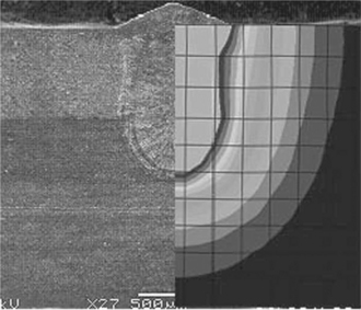
Figure 22.18 shows the comparison of molten pools between simulation and experiment. It can be seen in the figure that the simulated pool shape is similar to a vase shape, and the trend of the fusion line is in good agreement with the experimental results.
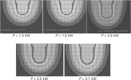
Figure 22.19 shows the simulated pool shapes for different laser powers with the welding speed S = 22 mm/s and defocus Dd = 0 mm unchanged. The laser powers are 1.3, 1.5, 2.0, 2.5 and 2.7 kW. According to the experiment results in Ref. [19], the simulated vase-shaped pool is consistent with the experimental results. As the laser power increases, so too does the weld penetration. By comparing the simulation and experimental results, when the laser power is higher than 2.5 kW, the weld penetration is more than 1.5 mm, and there are welded traces on the outer surface. When the laser power is less than 1.5 kW, the joint strength is too low to meet production requirements. Therefore, the range of power options for stainless steel vehicles is 1.5–2.5 kW.
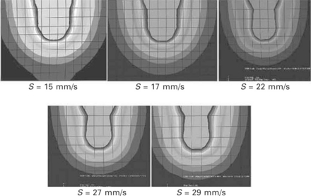
Figure 22.20 shows the simulated pool shapes for different welding speeds with the laser power P = 2.0 kW and defocus Dd = 0 mm unchanged. The welding speeds are 15, 17, 22, 27 and 29 mm/s. As the welding speed is increased, the weld penetration decreases. By comparing the simulation and experimental results, when the welding speed is less than 17 mm/s, the weld marks on the outer surface are obvious. When the welding speed is higher than 27 mm/s, the joint strength is too low to meet production requirements. Therefore, the range of welding speed options for stainless steel vehicles is 17–27 mm/s.
22.4 Quality control of laser welding joints in stainless steel vehicles
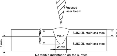
As an alternative to spot welding for the vehicle body, laser partial penetration welding of two stainless steel sheets is used. In laser partial-penetration lap welding, the laser beam is focused on the surface of the sample and the other parameters are controlled to guarantee partial-penetration welds without welded traces on the exterior surface. Figure 22.21 shows the joint arrangement for laser welding. By changing the welding parameters, such as laser power and welding speed, different widths and penetrations should be achieved. In order to understand the laser weld defects, the metal structure, convex surface and pores of the laser partial-penetration lap weld are observed, and these defects on the fatigue strength should be explored. The extent of laser weld penetration has an important impact on the fatigue strength. Considering the impact, non-destructive inspection methods are necessary to evaluate the extent of penetration.
22.4.1 Quality requests
The side wall structure of the railway vehicle is produced using a single-sided spot welding, which is an ideal way to ensure a good flatness of the outer surface of the side wall. Compared to arc welding, using resistance spot welding can reduce the body’s welding deformation. But due to the large number of weld spots, local deformation is induced. According to the JISZ3140-1989 [20] spot welding test, the strength of the laser welding joint should be bigger than that of the resistance spot welding joint. The amount of deformation should be less than 2 mm/m, and there should be no trace of the weld discoloration.
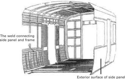
Figures 22.21 and 22.22 show the mode of laser welding of railway vehicles and the structure of the side panel, respectively.
22.4.2 Ultrasonic inspection
In order to confirm the state of penetration of the laser weld, a separate and wedge-shaped high-frequency probe with oscillator front-end should be used. The ultrasonic flaw detection was carried out inside the laser weld. The results showed that a high-frequency wave detection probe could easily identify and confirm the weld, and the scanning was over a large area. Currently, the quality test of the laser welding of railway vehicles relies only on joint-destructive testing, and there is no quality assessment of laser weld non-destructive testing to evaluate weld quality control standards and methods. So it is urgent to explore the use of ultrasonic probes to detect joint penetration and the state of penetration of the laser welding joint and it is necessary to increase development of non-destructive testing devices.
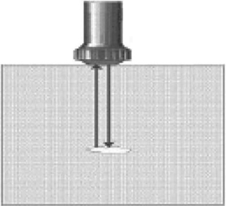
Figure 22.23 shows the working principle of the ultrasonic probe.
22.5 Future trends
Use of laser welding of austenitic stainless steel, aluminum alloy and low alloy high strength steel for the manufacture of railway vehicles is growing. Increasing the application of laser welding technology to railway vehicles will play an important role in increasing the competitive environment in the future marketplace, and this technology has significant commercial value.
The application of laser welding technology to railway vehicles has the following four prospects:
1. Laser welding technology has been applied to high-speed train bodies in Japan. In addition, laser welding technology will be applied on Siemens magnetic levitation train in Germany, DMU IC4 level high-speed train in Denmark, ETR500 high-speed commuter trains in Italy, and so on.
2. The manufacturing standard of high-speed stainless steel bodies has seen a substantial increase, and there is a possibility for it to replace aluminum. It is necessary to develop the manufacturing technology.
3. The trends in advanced body structure design are for the overall load-bearing structures to have no frame, a car shell roof and floor, and both sides made of laminated sheet, which sandwich a light structure. This kind of structure can be achieved by laser welding technology, and also reflects the structure of the advanced design concept.
4. When the overall body is produced by laser welding technology replacing resistance spot welding, the fatigue strength can be increased by 15% and the vehicle’s rigidity and strength are greatly improved, leading to a decrease in weight.
22.6 Sources of further information and advice
Laser welding technology of stainless steel vehicle car body
For the high-quality requirements of unpainted stainless steel body surface, although resistance spot welding can significantly improve the deformation of the surface state, there is still solid joint deformation at the surface. Major domestic and foreign companies that manufacture stainless steel rail passenger cars in recent years have begun to use laser welding to solve these problems. High-quality surface state and structural strength can be achieved by the partial penetration lap laser welding of the side panel structure.
Laser-MAG hybrid welding method for side body applications
The beam side body is currently welded by MAG welding methods, mostly using one-sided welding and surface rendering. MAG welding methods present the disadvantage that it is not easy to ensure adequate penetration. With a large welding current, welding speed is very low, resulting in thick deposited metal. Figure 22.24 shows that Laser-MAG hybrid welding can achieve a deeper penetration.
Laser welding of aluminum sheets
Currently, one of the main welding problems has been welding distortion of aluminum sheets. Especially in thin-walled aluminum Maglev car projects, welding of long seams is needed for 1 mm and 2 mm thick aluminum alloy sheets. The traditional method is MIG welding and the welding quality cannot meet the requirements of welding deformation. Laser welding and hybrid welding should be developed as new welding technologies to counter such problems in the future.
22.7 References
[1] Xue, K. The selection of material of city railway car body. Shanghai, China: Reaching of Railway Communication; 2003.
[2] Wang, J. Development and hope of laser welding technology. Shanghai, China: Laser Technology; 2001.
[3] Yamadori, Kawasaki Heavy Industries Technical Report, 2006.
[4] Dilthey, U., Wieschemann, A. Prospects by combining and coupling laser beam and arc welding processes. Welding in the World. 2000; 44(3):37–46.
[5] Samanta, S., Kumar, M., et al. Influence of welding speed on microstructure and oxidation behaviour of laser welded austenitic stainless steels. Iron and Steel Institute of Japan. 2006; 46(1):100–105.
[6] El-Batahgy, A. M, Effect of laser welding parameters on fusion zone shape and solidification structure of austenitic stainless steels. J Mater Lett. 1997; 32:155–163.
[7] Maren, G. In-laminate laser soldering–a gentle method to assemble and interconnect silicon solar cells to modules, 21st European Photovoltaic Solar Energy Conference. Germany: Dresden; 2006.
[8] Wang, H. Laser welding of 8 mm thick stainless steel plates. Chinese Journal of Lasers. 2003; 5:463–466.
[9] Arata, Y. Challenge of laser advanced material processing, Proceedings Conference on Laser Advanced Material Processing (LAMP’87). May: Osaka; 1987.
[10] Solana, P., Ocana, J. Mathematical model for penetration laser welding as a free boundary problem. J Phys D: Appl Phys. 1997; 30(9):1300–1313.
[11] Solana, P., Ocana, J. Mathematical model for penetration laser welding as a free boundary problem. J Phys D: Appl Phys. 1997; 30(9):1300–1313.
[12] Postacioglu, N., Kapadia, P., Dowden, J. Theoretical model of thermocapillary flows in laser welding. J Phys D: Appl Phys. 1991; 24(1):15–20.
[13] Upadhyaya, B. N, A highly efficient 5 kW peak power Nd:YAG laser with time-shared fiber optic beam delivery. Optics & Laser Technology. 2008; 40:337–342.
[14] Choo, R. T. C. Szekely J and David S A, On the calculation of the free surface temperature of gas-tungsten-arc weld pools from first principles: Part II modeling the weld pool and comparison with experiments. Metallurgical Transaction B. 1992; 23(6):371–384.
[15] Huzeng, R., Zhou, J. Application of ABAQUS simulation of laser welding temperature field. Laser Technology. 2007; 31(3):326–329.
[16] Tailor, G. A., Hushes, M., Pericleous, K., The application of three dimension finite vohme method to the modeling of welding phenomena 852–859,Sahm R., ed. Modeling of Casting, Welding and Advanced Solidification Process IX. Aachen: Shaker, 2002.
[17] Hu, Q. Finite element analysis of keyhole plasma arc welding temperature field. Jinan: Shandong University; 2007.
[18] Charg, W. S., Na, S. J. A study on the prediction of the laser weld shape with vary heat source equations and the thermal distortion of a small structure in micro-joining. Journal of Materials Processing Technology. 2002; 120(1):208–214.
[19] Wang, H., Wang, C. The investigation of partial penetration lap laser welding applied on stainless steel railway vehicles. Advanced Materials Research. 2010; 97–101:3832–3835.

