Laser welding of glass
Abstract:
Laser welding of glass enables monolithic joint structure providing excellent mechanical strength, high temperature stability and space selectivity in comparison with existing joining procedures without pre- and post-heating. For welding of glass, CW CO2 lasers and ultrashort pulse lasers (USPL) can be used. While CO2 laser welding can be used for welding glass with a small coefficient of thermal expansion (CTE) based on linear absorption process similar to metal welding, USPL is applicable to any glass without restriction of CTE based on nonlinear absorption. This chapter discusses laser-matter interaction, welding characteristics and applications of laser welding of glass.
11.1 Introduction
Glass can be welded without pre- and post-heating by two different approaches using continuous wave (CW) laser and ultrashort pulse laser (USPL) to which glass is opaque and transparent, respectively. In the former approach, the laser energy is absorbed at the surface of the glass plate by a linear process following the same principles as the laser welding of metal discussed in the other chapters. Some applications of glass welding by CW laser are described here, which include observations on keyhole-welding, spot welding for optical assembly and welding of optical fibers to a substrate.
In the latter approach, USPL is absorbed within bulk glass by a nonlinear process due to multiphoton ionization followed by avalanche ionization, enabling internal melting of glass plate without giving any damage at the surface of the glass plate. The internal melting by USPL has been attracting much attention due to its unique absorption process and thereby an innovative welding technique for glass has been realized by the recent advancement of USPL technologies. Interaction between USPL and bulk glass during welding is still under investigation, since USPL with average power high enough for glass welding became commercially available only within the last five years. So, interaction between USPL and glass is discussed in some detail, and overlap-welding technology is introduced.
This chapter contains fundamentals and applications of CW-laser and USPL laser welding techniques to glass, which is followed by a conclusion and future trends.
11.2 Features of glass welding
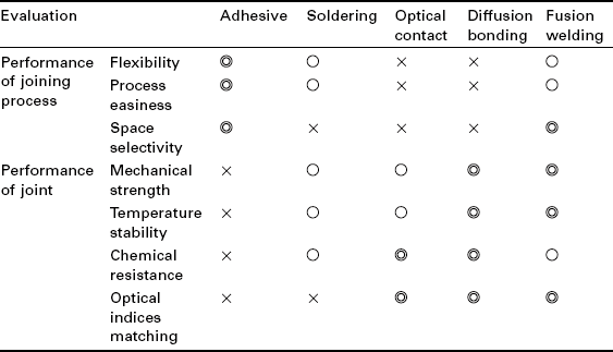
There exist a variety of procedures for joining glass pieces other than fusion welding discussed in this chapter. They include adhesive bonding [1], soldering [2], optical contact [3] and direct bonding (diffusion bonding) [4]. Different joint performances are required depending on the application field. Table 11.1 compares joining procedures of glass in terms of the process performance (flexibility, process easiness and space selectivity) and the joint performance (mechanical strength, temperature stability, chemical resistance and optical indices matching). In the applications to mechanical structures, for instance, mechanical strength and temperature stability will be important. For joining optical components like optical fibers, for instance, the mechanical strength and the efficiency of the transmission of the optical signal can be major concerns.
While adhesive is most widely used in different industrial fields due to excellent joining performance such as flexibility in positioning and filling the space between the glass pieces, it has major disadvantages in terms of joint performance such as mechanical strength, temperature stability and chemical resistance. In soldering, solder glass, whose melting temperature is lower than that of the glass piece, is inserted at the interface of the glass pieces, and the solder glass is selectively melted by heating in furnace or laser irradiation. These two joining procedures provide a joint performance lower than that of the glass pieces themselves for mechanical construction, and also have disadvantages of absorption and back reflection of the optical signal at the joint due to mismatch of the refractive indices for optical applications.
The optical contact has disadvantages in that very high surface flatness (λ/20) and surface roughness are needed, and the strength of the optical contact is approximately two orders lower than that of the base material [5] since the joining is based on van der Waals interaction [6]. Although the joint strength of diffusion bonding is as high as that of the base material, this process is not practical, since the joining is based on diffusion of atoms near the joint interface, which requires not only high flatness and surface roughness of the glass pieces, but very long heating time at high temperature and high pressure. Optical contact and diffusion also do not have space selectivity of the joining area.
Fusion welding is based on local melting to provide excellent performance in terms of joining process and weld joint. While traditional glassblowing can be used for joining glass components, there is a desire for development of more precise procedures with automation, especially for the miniature part of the process. Advantages of glass welding include the monolithic joint structure with excellent spatial resolution of the joining area and its simple joining procedure in contrast to diffusion bonding. The monolithic joint structure provides advantages including not only thermal and chemical stability and mechanical strength comparable to glass itself, but no transmission and reflection loss at the weld joint due to no discontinuity in the refractive indices in the applications to joining transmission optics.
Glass can be welded using two contrastive lasers, CW-laser [7] and USPL [8–10], to which glass is opaque and transparent, respectively. In the former case, CW (or normal pulse) CO2 laser (λ = 10.6 mm) is used where the laser energy is absorbed following the same principles as those of well-established laser welding technology of metal in the sense that the laser energy is absorbed at the surface of the material to be welded through linear absorption.
In the latter case, USPL with infrared wavelength (typically λ = 1.06 mm) is used, and the laser energy is absorbed only in the high intensity region in the focus volume through nonlinear absorption by multiphoton ionization followed by avalanche ionization without any absorbent. Since the laser energy is absorbed only in the focus volume and no laser energy is absorbed at the locations apart from the focus, the molten pool is embedded in the solid bulk glass. In overlap welding with USPL, the interface of the glass plates is selectively melted without giving any damage at the top and the bottom surfaces of the glass plates.
In laser welding of glass, prevention of cracks is one of the most important tasks, since local laser heating produces a steep temperature gradient so that cracks can be easily produced due to brittleness of glass at room temperature in contrast to metal. While tensile and compressive stress are developed by the local heating, cracks normally develop when the tensile stress exceeds the material strength, since the tensile strength of material is generally much smaller than the compressive strength.
11.3 Glass welding by continuous wave (CW) lasers
11.3.1 Fundamentals of CW laser welding
Welding modes
Glass is opaque to radiation in wavelength ranges of λ < 250 nm and λ > 3500 nme. One of the most useful lasers in these wavelength regions is the CO2 laser with a wavelength of λ = 10.6 mm. The Fresnel reflection at this wavelength is approximately 14%, and 86% is absorbed at the surface of the glass.
There are two types of glass welding using CO2 laser: thermal conduction and deep penetration (keyhole welding) depending on the laser intensity as in the case of laser welding of metal, as schematically shown in Fig. 11.1 [11]. When the power density of the laser beam is not high enough to heat the surface above the boiling temperature of the glass, the interior of the bulk glass is heated by thermal conduction from the surface (Fig. 11.1a), providing thermal conduction welding. Thermal conduction welding is useful in welding micro parts or thin sheets of glass, since the distance of thermal diffusion is limited due to low thermal diffusivity of glass. In thermal conduction welding, a rather large spot of laser beam is used at slow welding speeds. An application demonstrating hermetic sealing of a thin pressure-bearing quartz diaphragm to a thicker frame has been reported [12].
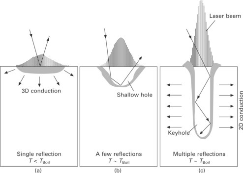
11.1 Schematic illustration showing different welding modes: (a) thermal conduction welding; (b) intermediate between thermal conduction and keyhole welding; (c) typical keyhole welding.
When the power density of the laser beam is high enough to heat the glass surface above the boiling temperature, the molten glass surface is depressed by the recoil pressure of the evaporation, and a shallow hole is produced. The keyhole grows deeper, when the laser beam is refocused to the bottom of the hole by the reflection at the wall of the hole (Fig. 11.1b). As the power density increases, the depth of the hole becomes deeper to produce a deep keyhole. Then the inside bulk glass is directly heated by the laser beam guided in the keyhole through multi-reflections (Fig. 11.1c).
Residual stress in melting containing free surface
It is not simple to evaluate the exact stress field in welding, and it has to be numerically simulated based on three-dimensional elasto-plastic analyses. However, the stress developed in fusion welding of glass can be qualitatively estimated by a simple three-bar model consisting of a center bar A and sidebars B as shown in Fig. 11.2. In this one-dimensional model, it is assumed that the three vertical bars are connected to rigid horizontal bars at their ends, and the laser energy is absorbed in A. In the early stage of the heating period (Fig. 11.2a: Phase I), compressive stress and tensile stress are elastically developed in A and B, respectively, since thermal expansion of A is constrained by B. When A is melted (or yielded), the resultant stress field depends on whether or not the molten region can be plastically deformed. In the case of CO2 laser welding of glass, the molten region can be plastically deformed. Then the stress in A and B is completely released when A is melted, since the melted region contains free surface and hence the plastic deformation of the molten region can occur freely. Thus the lengths of A and B return to the original values on melting without producing any stress (Fig. 11.2b: Phase II).
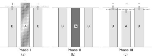
11.2 Three-bar model in CO2 laser welding of glass, assuming laser energy is absorbed in A. (a) Heating period (elastic deformation). (b) Melting (stress is released). (c) Cooling periods. + and – represent tensile and compressive stress, respectively.
In the cooling period after the solidification of the molten region, the shrinkage of A is constrained by B (Fig. 11.2c: Phase III). Therefore the tensile and compressive stresses are left in A and B, respectively, when A is cooled down to room temperature. Cracks are developed in A if the tensile stress (called shrinkage stress) exceeds the mechanical strength of the glass, since glass is brittle at room temperature. The residual tensile stress in A increases with increasing thermal expansion coefficient of the glass. Therefore in CO2 laser welding of glass, crack-free welding is possible only in glass having a small thermal expansion coefficient like fused silica, as cracks are easily developed by the shrinkage stress. The shrinkage stress also increases with increasing absorbed laser energy. If the absorbed laser energy is not large enough to melt (or yield) A, no residual stress is left in Phase III, since no plastic deformation occurs and hence the shrinkage stress is compensated by the compressive stress produced in Phase I. The formation mechanism of the residual stress in glass welding is basically the same as metal welding. However, cracks can normally be prevented in metal welding, since metal has ductility even at room temperature in contrast to glass.
In the three-bar model, it is implicitly assumed that cracks due to the tensile stress in B in Phase I can be suppressed. This assumption is justified by the direct observation of glass welding by CO2 laser as will be shown later. No cracks are observed during CO2 laser welding of glass as will be shown below (see Figs 11.3-11.6). In the following sections, some applications of CO2 laser welding of glass are introduced.
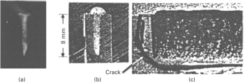
11.3 Keyhole welding in soda-lime glass using electron beam (150 kV-0.5 mA; 40 mm/s). (a) Keyhole observed during welding. (b) Cross-section of weld bead. (c) Side view of weld bead, Cracks are developed after long delay at room temperature [7].
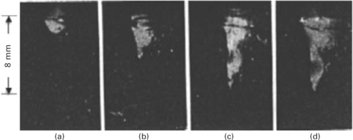
11.4 CO2 laser welding of soda-lime glass at laser power of (a) 50 W, (b) 70 W, (c) 100 W and (d) 120 W at welding speed of v = 70 mm/s. Focus point was located 2 mm above the surface [7].
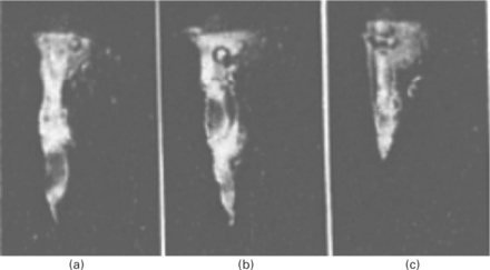
11.5 CO2 laser welding of soda-lime glass at 150 W at welding speed of (a) 10 mm/s, (b) 60 mm/s and (c) 100 mm/s [7].
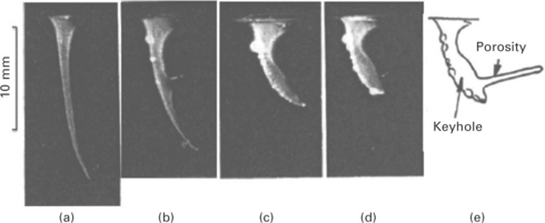
11.6 CO2 laser welding of 96% silicate Vycol glass at 90 W at welding speeds of (a) 10 mm/s, (b) 20 mm/s, (c) 30 mm/s, and (d) 40 mm/s. (e) Schematics at 40 mm/s [7].
11.3.2 Applications of CO2 laser welding
Observation of keyhole welding process
Keyhole welding is widely used for joining metal using a high power density source such as a laser beam and electron beam due to the advantage that thick sections can be welded in a single path with reduced heat-affected zone. The keyhole welding process, however, is not fully understood, since the dynamic behavior of the keyhole and the molten material is very complicated. Thus the keyhole welding process has been investigated experimentally by X-ray transmission imaging [13]. The X-ray transmission images, however, are not clear enough to investigate the dynamic behavior of the keyhole precisely.
It was found that a keyhole can be produced by focusing CO2 laser in glass, where the surface tension force is balanced with the recoil pressure of the evaporation at the keyhole wall [7]. When the glass sample moves forward, the keyhole is maintained stably by burying the backside of the keyhole with molten glass continuously in a similar way to the keyhole welding of metal. This means that the dynamic behavior of the keyhole welding process can be directly observed in glass with much higher spatial and temporal resolution than the X-ray transmission images in metal welding. This technique also provides a useful measure to investigate the effects of thermal properties such as viscosity and thermal conductivity on welding phenomena.
Figure 11.3(a) shows the side view of the keyhole welding in soda-lime glass by electron beam in vacuum. Interestingly, no influence of charge-up of electrons is found. High-speed photographs clearly show that as the glass sample moves forward at a constant speed, the backside of the keyhole is continuously buried by the molten glass to maintain a stable keyhole. The electron beam reaches directly the bottom of the vertical keyhole unlike the case of CO2 laser welding of glass as will be described below. The cross-section of the molten zone is similar to that of keyhole welding of metal as shown in Fig. 11.3(b). This suggests that glass is a useful material for observing the dynamic behavior of the keyhole and the molten material.
It is noted that no cracks are developed during welding in spite of the steep temperature gradient developed during localized heating. This is considered to be because the heat-affected region gains ductility to prevent cracks in Phase I. However, cracks are always developed when the welded sample is cooled down to room temperature, sometimes after a very long delay as shown in Fig. 11.3(c). This indicates that the cracks are caused by shrinkage stress in Phase III, and that crack-free keyhole welding of sodalime glass is not possible because of the large thermal expansion coefficient of soda-lime glass, α = 94 × 10- 7/°C (T = 0 − 300 °C). Crack-free welding is limited to glass having a thermal expansion coefficient one order smaller than soda-lime glass like fused silica or Vycol glass using beam sources to which glass is opaque as shown below.
Figure 11.4 shows the laser welding of soda-lime glass observed at different laser powers at a welding speed of 70 mm/s. In this experiment, a multimode CO2 laser beam with a rather large focus diameter of 0.3 mm was used to make the observation easier, and the high-speed photographs were taken without lighting. A shallow keyhole is observed at 50 W (Fig. 11.4a). It grows quickly at 70 W by refocusing the reflected laser beam at the wall to the bottom of the keyhole. The inclination angle of the front wall of the keyhole in CO2 laser welding is larger than that in electron welding, suggesting that CO2 laser energy is absorbed by the multiple reflections at the keyhole wall. No humping and closure of the keyhole entrance were observed. The flow velocity of the molten glass was considerably slower than that of metal due to the larger viscosity of the molten glass than that of metal. This suggests that the instabilities of welding such as humping bead and closure of the keyhole entrance in metal welding are related to larger flow velocity of the molten metal. However, the dynamics of the keyhole process observed in glass is basically the same as that of metal.
Figure 11.5 shows the keyhole observed at different welding speeds at a laser power of 150 W. As the translation speed increases, the keyhole becomes shorter, and the front wall of the keyhole is somewhat bent as the bottom of the keyhole is approached.
Figure 11.6 shows the photographs observed in 96% silicate glass (Corning Vycol) at 90 W at different welding speeds. The keyhole is considerably thinner and longer than that of soda-lime glass. The thickness of the molten layer surrounding the keyhole appears to be much thinner (almost invisible near the bottom of the keyhole), since the viscosity of the molten glass in this material is much larger than that of soda-lime glass.
At a welding speed of 10 mm/s, a thin and long keyhole with large bending is produced indicating that at least three to four reflections are needed for the laser beam to reach the bottom of the keyhole. It is interesting to note that the keyhole swings back and forth near the bottom at a frequency of several tens Hz like a snake motion. Several inflection points are observed and the keyhole is bent even in the opposite direction with respect to the welding motion due to larger recoil pressure of evaporation at the reflecting points as shown in Fig. 11.7. This suggests that the laser intensity at the keyhole wall is not uniform. Such a stable keyhole cannot be produced in soda-lime glass, because the stability of the keyhole is prevented by the flow of the liquid glass.
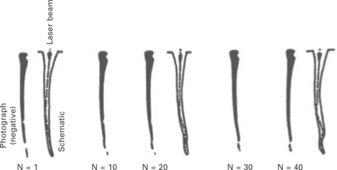
11.7 High-speed photographs of keyhole in Vycol glass (150 W, 10 mm/s, 1000 f/s). The keyhole swings back and forth in a snake-like motion. Beam propagation in the keyhole is drawn in schematics (N: frame number) [7].
At welding speeds faster than 20 mm/s, the inclination of the keyhole at the front wall becomes larger with accompanying increased diameter of the keyhole, and a long porosity is produced at the back of the keyhole, suggesting the burial by the molten glass at the backside of the keyhole is only partially successful since the flow velocity of the molten glass cannot keep up with the welding speed. Such a porosity is not observed in sodalime glass, suggesting higher welding speeds require larger fluidity of molten glass for obtaining sound keyhole welding.
It is known that the molten material is driven downward along the front wall of the keyhole by the recoil pressure of evaporation. If the melt flow stagnates due to larger viscosity of the molten material, the front wall has to be inclined so that the incident laser beam is absorbed at a larger incident angle to increase the evaporation recoil pressure. Figure 11.6 clearly shows that the inclination angle becomes larger with larger viscosity of the melt in Vycol. In laser welding of metal, bending of keyhole is much smaller, because the molten metal flows down quickly along the front wall due to smaller viscosity.
It is noted that no cracks were found in Vycol after cooling to room temperature unlike the case of soda-lime glass. This suggests that the CO2 laser can be used for welding of Vycol. This is because the thermal expansion coefficient of this material is as small as 7.6 X 10- 7/°C, at least one order smaller than that of soda-lime glass, so that the shrinkage stress developed in Phase III can be suppressed below the tensile strength of the material.
Spot welding for optical assembly
A spot welding technique using a CO2 laser was developed to join thick glass plates of fused silica with a small deformation, and was applied to assembly of the rooftop structure consisting of thick glass plates with a thickness of 10 mm [14]. Laser welding was adopted because it allows joining of glass pieces with an extremely high level of angle accuracy, while providing high stiffness and excellent stability over a large temperature range. This procedure was developed as a first step toward the fabrication of complete corner cubes.
A side of the glass piece with dimensions of 50 mm × 50 mm × 10 mm was set in contact with the second piece of 50 mm × 70 mm × 10 mm. The first piece was joined at a location 10 mm apart from the edge of the second piece to allow the formation of the welded spots located far enough from the edges of the glass pieces. For welding the thick glass plates, holes (diameter = 1.5 mm, depth = 9.2 mm, leaving a 800 μm layer) are drilled by an ultrasonic drill into the second glass piece to make the junction accessible, as shown in Fig. 11.8. The glass piece is deformed by the drilling process at the surface to form small bumps with a height less than 60 nm and a diameter of 2 mm. The glass pieces to be welded were pressed together by a mechanical holder. A Gaussian beam was focused into the bottom of the drilled hole to provide a focused waist of 300 μm. Average powers ranging between 20 and 70 W were irradiated at different exposure programs consisting of preheating by linearly increasing power, slowly decaying laser power for thermal relaxation and laser process duration. Total durations of the laser exposition recipes ranged from 110 to 900 s.
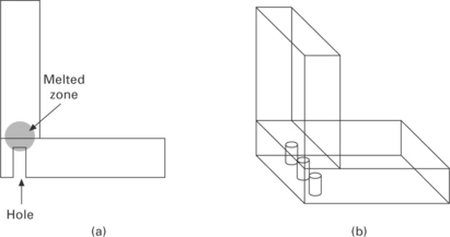
11.8 Spot welding of thick plates by CO2 laser: (a) side view; (b) perspective view. [14]
It is interesting to note that the glass pieces are pulled against each other by the shrinkage of the molten material during the cooling process, so that two glass pieces are brought into visual optical contact. The laser-welded rooftop assembly was coated with gold in a sputtering system after laser welding. This results in an interesting feature of the assembly that the junction between the two pieces cannot be distinguished when viewed from the gold-coated side (Fig. 11.9). This is because the upper glass piece had no chamfer at the interface between the principal face and the contact face. This excellent optical quality junction can be an advantage for some applications.
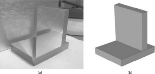
11.9 Bare gold-coated laser-welded rooftop. (a) Photograph. The junction between two glass pieces cannot be seen on the photograph. (b) Drawing of the photograph. [14]
The tensile strength of the weld spot was measured. The results show that the joint strength ranges from 10 kg to 30 kg per spot, which corresponds to approximately as large as 50–150 MPa, assuming the diameter of the spot welding is 1.5 mm. This indicates two welded spots were sufficient to provide a strong junction between the substrates.
The beam deviation error of the rooftop by the spot welding was measured with the Mark GPIxps interferometer from Zygo having an accuracy of ± 0.05 arc second. The result indicates the angle deviation from 90° was 1.87 arc second. Considering that the width of the junction area between the two pieces of the assemblies is 10 mm, deviation of 1.87 arc second corresponds to 90 nm height error along 10 mm length. The measured deviation error indicates the welding process is very promising for the fabrication of high accuracy assembly.
The results of the wave front deformation errors also show the spot welding technique is very promising in keeping the quality of the initial optical faces. Melting and shrinking associated with the welding process provided negligible effect on the surface of the optical piece thanks to the distance separating the surface and the melted zones and the limited power range that minimized the side of the melted zone. One of the main advantages of laser welding is its stability over wide temperature ranges due to its monolithic structure. High temperature stability was verified by measuring the reflected wave front and angle over a temperature range between − 60 °C and + 40 °C. These tests indicated that the wave front distortion stayed below λ/10 and its value varied less than 0.04 X. In the same temperature range, the variations of the assembly angle were all within a 0.7 arc second interval, showing the spot welding of thick glass plates is promising.
Welding of optical fiber for fiber optical rotary joints (FORJ)
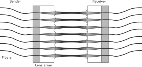
An interesting application of glass welding in the optical field is found in fiber optical rotary joints (FORJ), which are used for transmission at high data rates, for instance, between rotating radar antennas or medical sensors and stationary systems for analysis and further processing of the data. To establish an optical connection between the rotating and stationary fiber bundle, the optical fibers have to be attached to an array of collimator lenses, and the beam is focused onto the fiber core again and coupled into it on the opposite side, as schematically shown in Fig. 11.10.
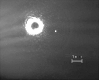
The existing procedure for connecting fibers to collimator lenses in the production process of FORJ is adhesive bonding. This procedure, however, has disadvantages in that the laser energy absorbed in the adhesive can heat up the adhesive to reduce the mechanical stability. The temperature rise also changes the refractive index of the adhesive, resulting in an increase in the back reflection. As an alternative to adhesive bonding, a CO2 laser welding technique has been developed. For heating the glass fiber at the end face and the glass substrate uniformly, a ring-shaped laser beam is ideal to heat the whole circumference of the glass fiber. In order to convert the Gaussian beam into the ring beam, the Schwarzschild objective was used, which consists of two spherical mirrors having concave and convex geometries. A laser welding system was designed to allow a minimum fiber pitch of approximately 1 mm [15].
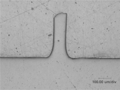
The laser-irradiated region thus obtained is shown in Fig. 11.11, and the laser welding is of thermal conduction mode. Figure 11.12 shows the cross section of the weld joint, indicating the optical fiber is excellently welded to the substrate with a good concave weld seam. The mechanical strength evaluated by a pulling test of the welded optical fiber was as high as 326 MPa, which is significantly higher than the value of existing adhesive joining, 33 MPa [16].
11.11 Profile of collimated beam provided by Schwarzschild objective [15]
11.12 Cross section of optical fiber welded to glass substrate [15].
Back reflection is an important factor for characterizing the quality of the optical data transmission system. The back reflection can be specified as an attenuation value (return loss). A return loss of around − 40 dB is the best achievable value for adhesive joints [17]. The measured mean value of the weld joint is − 49.4 dB with a deviation of 0.6 dB, which is in the range of the measurement accuracy. So there is an enhancement of the return loss of nearly 10 dB, corresponding to an absolute improvement of a factor of 10.
11.4 Glass welding by ultrashort pulse lasers (USPL)
11.4.1 Fundamentals of USPL welding of glass
Nonlinear absorption process
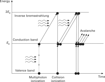
Ultrashort pulse laser (USPL) is a useful energy source for internal modification of glass due to its unique absorption process. When glass is irradiated by infrared CW laser with normal intensity, no laser energy is absorbed in the glass, since the band gap energy Eg is larger than the photon energy. When infrared USPL is tightly focused into bulk glass, the laser energy is absorbed into glass by a nonlinear absorption mechanism by multiphoton ionization to promote a valence electron to the conduction band as is schematically shown in Fig. 11.13 [18, 19]. Then the free electron gains kinetic energy by absorbing the laser energy by Inverse Bremsstrahlung. When the kinetic energy of a free electron exceeds the conduction band minimum by more than Eg, the electron can then collisionally ionize another electron from the valence band (avalanche ionization). While the breakdown process is dominated by the multiphoton ionization in the early period of the laser pulse, the avalanche ionization starts to govern the breakdown dynamics to produce more free electrons thereafter.
Recent rapid advancement of USPL technology [20] has enabled attractive applications of internal modification of glass such as refractive index change [21], nano-grating [22], selective etching [23], three-dimensional memory [24] and fusion welding [5, 8, 10, 25]. In particular, the advent of USPL with high-pulse repetition rates has made it possible to achieve internal modification at high throughput thanks to cumulative heating arising when the interval between laser pulses is less than the time required for the absorbed laser energy to diffuse out of the laser-irradiated region [10, 26].
The laser energy absorbed by free electrons is transferred to lattice (atoms) to elevate the temperature of the glass after the laser pulse. Then the temperature field is developed in bulk glass by thermal diffusion to produce a molten region. The thermal conduction theory can be utilized to simulate the temperature distribution or the melt dimensions in the glass, assuming the intensity distribution of the absorbed laser energy is known [10].
Melting structure of glass
Since avalanche ionization requires seed electrons, which can be provided by multiphoton ionization, the laser-absorption region is limited only to the focus volume, enabling localized internal melting of bulk glass, if the focus is located inside the bulk glass. The glass molten pool can actually be observed by focusing USPL at the rear surface of the glass plate. Figure 11.14 shows a SEM photograph of the molten pools with a size of 3–4 mm produced by single laser pulses of 10 ps pulse duration [9].
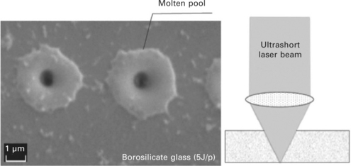
11.14 Local melting of glass plate (Schott D263) at the bottom surface using USPL (τp = 10 ps, λ = 1.064 μm) [9].
Figure 11.15 shows a cross section of overlap welding of borosilicate glass plates (Corning 0211) [27]. Two advantages are found in the figure in comparison with CO2 laser welding. First, selective melting is possible only at the interface of glass plates without any damage at the top and bottom surfaces of the glass plates. Second, crack-free overlap welding is possible with most commercially available glass materials even though their thermal expansion coefficient is 10 times larger than fused silica. The cross section of the weld joint consists of a teardrop-shaped inner region and an elliptical outer region as seen in Fig. 11.15(b). The glass plates are joined together within the outer region, indicating the glass is melted in the outer region. Since glass does not show a clear melting point, the characteristic temperature of the outer structure (Tout) is defined as the forming temperature of the glass, of which viscosity is η = 104 dPas. The inner structure corresponds to the region where the laser beam is absorbed as discussed later [10].
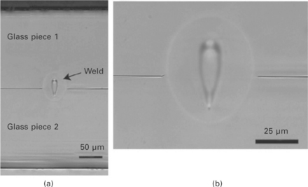
11.15 Example of overlapped welding of borosilicate glass (Corning 0211) using USPL (τp = 360 fs, λ = 1.045 mm, f = 1 MHz): (a) cross section of overlap welding; (b) magnified picture [27].
The stress field developed in USPL welding of glass is different from that in CO2 laser welding. Although no difference is found between USPL and CO2 laser in Phase I, the plastic deformation with the internal melting is prevented by surrounding solid glass in Phase II, since the molten region produced by USPL is embedded in the solid bulk glass. The embedded molten region is considered to behave like an elastic body, so that no residual stress is produced in Phase III. This is because the stresses in A and B induced during Phases II and III are elastic, although detailed study is needed to understand the exact mechanism.
Thermal conduction model for analyzing laser absorption
A simulation model has been developed to correlate between the intensity distribution of the average absorbed laser power and the temperature distribution in a glass sample by Miyamoto et al. [10], assuming the thermal properties are independent of temperature, for simplicity. The steady temperature distribution is given by:
where w(z) is average absorbed laser power at z, l is the length of the absorption region, K is the thermal conductivity, α is thermal diffusivity given by K/cρ (c = specific heat and ρ = density), T0 = room temperature and s2 = x2 + y2 + (z − z’ )2. In this model, it is assumed that a line heat source with continuous heat delivery [28] of w (z) appears in an infinite solid moving at a constant speed of v along the x-axis, and w(z) is given by w(z) = Q(z)f, where Q(z) is pulse energy absorbed at location of z and f is pulse repetition rate. Despite the actual laser beam having finite spot size with pulsed energy delivery, the simple line heat source model with continuous heat delivery can be used to calculate the temperature at the contour of the molten zone, because the temperature rise at locations apart from the heat source is spatially and temporally averaged. Using the simulation model given by Eq. [11.1], one can determine w (z) and its extent l by fitting the simulated isothermal line of the characteristic temperature to the experimental outer structure (melt region) [10].
Figure 11.16 shows the experimental cross section of borosilicate glass and the simulated isothermal lines of the inner and outer regions, assuming that w(z) is given by a simple quadratic function. Excellent agreement is found between the simulated isothermal lines and the experimental contours of the outer structure of Tout = 1,051 °C, which is the forming temperature of the material (Schott D263). The intensity distribution w(z) is also plotted in the figure. The length l agrees with the vertical length of the tear-drop-shaped inner structure. This means that the inner structure is defined as the region where the laser energy is absorbed.
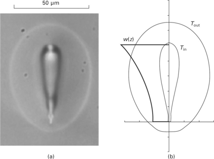
11.16 (a) Cross section of modified zone of borosilicate glass (Schott D263) using USPL (τp = 10 ps, λ = 1.06 μm, f = 500 kHz) at 20 mm/s. (b) Simulated isothermal lines at Tout = 1051 °C and Tin = 3600 °C [10].
Nonlinear absorptivity
Figure 11.17(a) shows the cross sections of borosilicate glass at different pulse energies obtained at a constant welding speed of 20 mm/s. The geometrical focus was determined at the bottom tip of the inner structure from the modified region at lowest limit of internal melting assuming the self-focusing [29] is negligible. The inner structure, which corresponds to the laser-absorbed region [10], extends toward the incoming laser side as the pulse energy increases. The outer region (molten region) also extends in accordance with the extension of the inner structure. Figure 11.17(b) shows the cross sections at different pulse repetition rates at a constant pulse energy of 3.8 μJ. The inner structure also increases as the pulse repetition rate increases. The nonlinear absorptivity ACal is given by [10]:
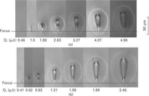
11.17 Cross section of modified zone of borosilicate glass (Schott 263) using USPL (tp = 10 ps, I = 1.06 mm, v = 20 mm/s) at pulse repetition rate of (a) 200 kHz and (b) 500 kHz.
where f is pulse repetition rate and Q0 is pulse energy. Nonlinear absorptivity can also be determined experimentally by measuring the transmitted pulse energy below the glass plate (see the inset of Fig. 11.18). Since the reflection and scattering of the laser beam by the plasma induced in bulk glass is negligible [30], the nonlinear absorptivity A is given by [9, 10]:
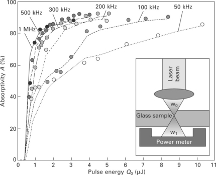
11.18 Nonlinear absorptivity of USPL (τp = 10 ps) at different pulse energies and pulse repetition rates. Data points and solid lines show simulated and experimental values, respectively [10].
where Q0 is incident pulse energy, Qt is transmitted pulse energy and R is Fresnel reflectivity of the glass plate.
Figure 11.18 shows the simulated and the experimental nonlinear absorptivity at different pulse energies and pulse repetition rates, showing excellent agreement between the simulated and the experimental values. The simulation model can predict the nonlinear absorptivity with an uncertainty less than ± 3%. The nonlinear absorptivity increases with increasing pulse energy, since the multiphoton ionization rate increases with increasing pulse energy. The nonlinear absorptivity also increases with increasing pulse repetition rate at constant pulse energy. This can be attributed to the heat accumulation effect; the density of the thermally excited free electrons to the conduction band increases due to the heat accumulation, and contributes as seed electrons for avalanche ionization [10], as shown below.
Figure 11.19 shows the simulated absorption region l plotted vs. the average absorbed power Wab (= Qabf : Qab = absorbed pulse energy) for pulse durations of 10 ps and 400 fs. The length of the laser absorption region l increases monotonically with increasing Wab independently of the pulse repetition rate, the pulse energy and the duration of the laser pulse.
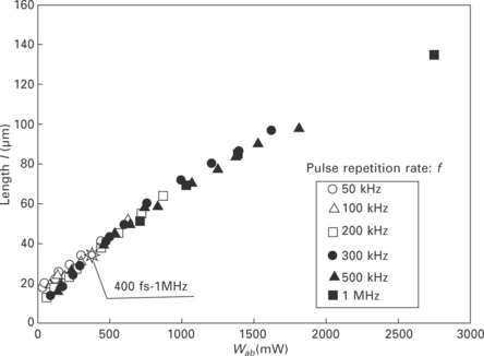
11.19 Length of laser absorbed region I vs. Wab (= ACalfQ0) at different energies Q0 and repetition rates of laser pulse f at τp = 10 ps. Data for τp = 400 fs are also plotted [10].
11.4.2 Overlap welding of glass plates
Mechanical strength of internally melted zone
Overlap welding technology has been developed with Foturan glass (Schott), which is widely used for three-dimensional structuring of components and is finding increasing use in devices ranging in application from the medical to the development of miniaturized satellites [31–33]. Prior to evaluating the mechanical strength of the overlap weld joint, single glass samples of Foturan glass were internally melted using USPL, and the mechanical strength of the molten zone was tested. The laser-irradiated samples were lapped and polished parallel to the melt line to expose the maximum width of the melt line to the surface. Then the samples were cut perpendicularly to the melt line, and the mechanical strength was determined with a three-point bending test by applying the maximum stress at the molten region.
Figure 11.20 shows the mechanical strength determined at different pulse repetition rates f and translation speeds v. The strength of the virgin material is in the region of 115–200 MPa (average value: 152 MPa), and the average value of all the internally melted samples (60 data points in total) is approximately 145 MPa, which is equivalent to the virgin or base material, showing no reduction in the mechanical strength due to internal melting. This is because no shrinkage stress is left at room temperature as mentioned above. However, the strength of the internally melted single plate is approximately 30 MPa lower than that of the base material at the lowest pulse repetition rate of f = 0.2 MHz, suggesting that some slight damage is produced when the peak intensity of USPL is too high. There is a tendency for the strength to increase with increasing v and f, reaching values equivalent to or even higher than that of the base material.
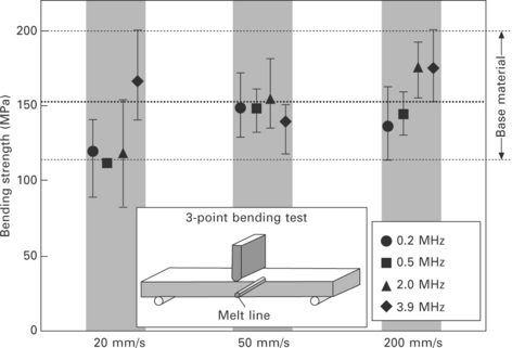
11.20 Mechanical strength of internally melted single Foturan sample determined by a three-point bending test at different f and v at a constant average laser power of 2.5 W. [5]
The bending strength data of the internally melted single sample is replotted as a function of the averaged absorbed laser power Wab in Fig. 11.21. The shaded zone in the figure highlights the region where the measured data distributes. While the mechanical strength is lower than the base material for larger Wab values, there is a net positive effect on the mechanical strength with decreasing Wab. As Wab decreases, the mechanical strength increases such that in the region Wab < 1.0 W there is the possibility of strengthening the material beyond the strength of the base material. Similar results with the internally melted single plate of fused silica with 10 ps are also reported [34]. These results are in accordance with the results using fs laser pulses, showing the strengthening of bulk glass by the irradiation of USPL that were evaluated by different testing procedures including the four-point bending test [35], the double torsion test [36] and nano-indentation [37, 38].
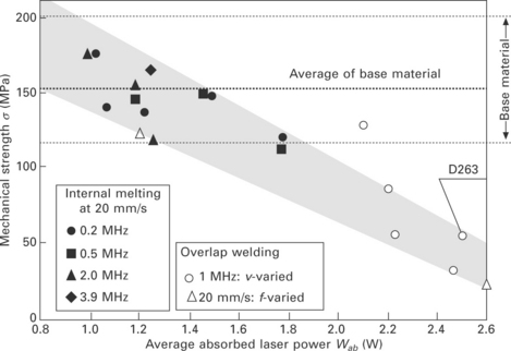
11.21 Mechanical strength of internally melted Foturan (single glass sample) and overlap-welded joint plotted in Foturan glass vs. average absorbed laser power Wab. The result of overlap welding of D263 is also plotted [5].
Laser welding system
Figure 11.22 shows the laser welding system of glass using USPL. Optical contact is strongly recommended to prevent the molten glass from flowing out of the laser-irradiated region. The optical contact is marked by a lack of reflections from the joining surfaces, since the gap between the plates is small enough to excite evanescent waves by an impinging light wave at the surface of the first glass part, almost without attenuation, a propagating wave inside the other part [39]. The optical contact is available by facing the commercially available float glass plates together, if the glass surfaces are carefully cleaned.
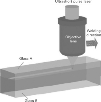
11.22 Schematic illustration of overlap welding of glass plates with optical contact. USPL is tightly focused by an objective lens for optical microscopy.
For focusing USPL tightly into bulk glass to realize nonlinear absorption, an objective lens for the microscope can be used. No absorbent is needed in spite of the fact that the glass is transparent to the laser wavelength, since the laser energy is absorbed by nonlinear absorption. The welding can be carried out at room temperature without pre- and post-heating. The focus location should be adjusted a little below the interface of the glass plates in order to make the widest molten region at the interface, since the absorption region extends upward as the average absorbed power Wab increases, as shown in Figs 11.17 and 11.19.
USPL welding of glass has a lot of advantages, which include
• welding is possible in a clean room due to no fume emission
• crack-free welding is possible independently of thermal expansion coefficient
• only the interface is selectively melted without absorbent
• high throughput welding is possible
• high mechanical strength of the weld joint is available with hermeticity.
Overlap welding
Figure 11.23 shows the peeled-off sample of overlap welding [9]. The fractured face does not show the original flat face but has an irregular appearance, suggesting that the two plates were strongly joined with vacuum tightness.
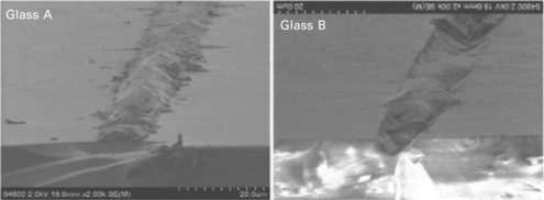
11.23 SEM photograph of the peeled-off weld joint in overlap welding of D263 [9].
Figure 11.24 shows the cross section of multi-path welding with a separation of 15 mm for borosilicate glass [34]. No cracks were developed with overlaying the beads, showing excellent versatility of the USPL welding of glass and the possibility to increase the joint strength without restriction of the overlay number.
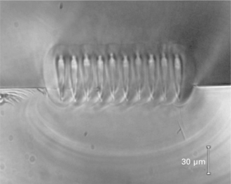
11.24 Multipath overlap welding of borosilicate glass of D263. The weld paths are overlapped with a separation of 15 mm (τp = 10 ps, f = 640 kHz, v = 20 mm/s) [34].
The mechanical strength of the overlap weld joint was evaluated by a shear test. In evaluating shear strength, the effect of the optical contact force FOC has to be taken into account [5], since the attractive force caused by van der Waals interactions works at the interface [6]. Figure 11.25 shows the shear force FOC required to break the optical contact between commercially available float glass plates without welding plotted as a function of optical contact area SOC. The optical contact force per unit area σOC (= FOC/SOC) is approximately 1.5 MPa at L = 1 mm, and tends to decrease with increasing SOC.
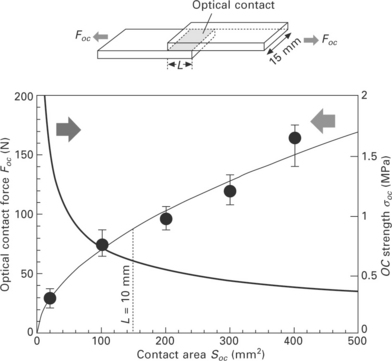
11.25 Shear force to break optical contact FOC plotted vs. contact area SOC. The optical contact force σOC is also plotted [5].
Overlap welding was performed with L = 10 mm corresponding to FOC ≈ 88 N (σOC ≈ 0.6 MPa), which is strong enough to keep optical contact in handling the sample for the welding operation [5]. While σOC ≈ 0.6 MPa is approximately two orders smaller than the strength of the glass, L = 10 mm is also two orders larger than the typical width of the weld bead. Therefore the strength of the weld joint σW was determined by subtracting the optical contact force FOC from the rupture load FRUP, and then dividing by the cross-sectional area of the weld bead SW as is given by the following equation [5, 39]:
Overlap welding was performed at different pulse repetition rates and translation speeds. Figure 11.26(a) shows the rupture load FRUP and the welded area SW plotted as a function of translation speed v at a constant pulse repetition rate of f = 1 MHz. Figure 11.26(b) shows FRUP and SW plotted as a function of pulse repetition rate at a constant translation speed of v = 20 mm/s. It is noticeable that the rupture strength FRUP is increasing in spite of the fact that the width of the weld bead decreases as the translation speed v or pulse repetition rate f increases.
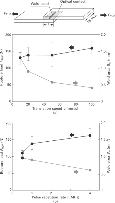
11.26 Effect of (a) translation speed at f = 1 MHz and (b) pulse repetition rate at v = 20 mm/s on the rupture strength and weld area of the overlap-weld samples. (L = 10 mm, length of weld path = 8 ~ 9 mm) [5].
The weld joint strength oW was calculated by Eq. [11.4] using the data plotted in Fig. 11.26, and is plotted vs. average absorbed laser power Wab in Fig. 11.21. Although some data scattering is found, most data points of the overlap weld joint fall in the zone that highlights the data from the internal melt single plate studies, suggesting that higher joint strength can also be obtained at reduced Wab.
11.5 Conclusion and future trends
Although glass is widely used in a variety of industrial fields due to its excellent physical and chemical properties, the welding technology of glass has not been used widely in industry, and the assembly of glass parts is actually dependent on technologies other than welding at the moment. This is because only CO2 lasers have been used for long time, and crack-free welding is available only in glass having low thermal expansion coefficient such as fused silica or Vycol due to cracks caused by the shrinkage stress.
It is expected that such a situation will be changed dramatically by the recently developed novel welding technology of glass using ultrashort pulse laser (USPL). This welding technology has been attracting much attention, because of many of the advantages discussed above. Among these, most importantly cracks can be prevented, and hence most commercially available glass can be welded without pre- and post-heating independently of the thermal expansion coefficient. It is expected USPL welding technology will become popular in glass-made products in a variety of micro applications such as electronics packaging, MEMS and micro optics in different industrial fields, as is the case for laser welding technologies for metal. Fundamental research work is, however, still needed in parallel to developing industrial applications of USPL welding of glass, since the laser-matter interaction during the welding process has not yet been fully understood.
11.6 References
[1] Tong, L., Speit, J. K., Fernlund, G., Recent Advances in Structural Joints, Dordrecht: Kluwer Academic Publishers, 27–66. 2003.
[2] Chaminade, C., Olowinsky, A., Kind, H. Laser-based glass soldering for MEMS packaging. Proc. 26th Int Congress on Application of Lasers and Electro-Optics (ICALEO). 2007; 143–148.
[3] Kachkin, S. S., Lisitsyn, Yu. V. Optical-contact bonding strength of glass components. Sov. J. Opt. Technol. 1989; 47:159–161.
[4] Shimbo, M., Fukukawa, K., Fukuda, K., Tanzawa, K. Silicon-to-silicon direct bonding method. J. Appl. Phys. 1986; 60:2987–2989.
[5] Miyamoto, I., Cvecek, K., Okamoto, Y., Schmidt, M., Helvajian, H. Characteristics of laser absorption and welding in FOTURAN glass by ultrashort laser pulses. Optics Express. 2011; 19:22961–22973.
[6] Greco, V., Marchesini, F., Molesini, G. Optical contact and van der Waals interactions: the role of the surface topography in determining the bonding strength of thick plates. J. Opt. A: Pure Appl. Opt.. 2001; 3:85–88.
[7] Arata, Y., Maruo, H., Miyamoto, I., Takeuchi, S. Dynamic behavior of laser welding and cutting. Proc. Symp. Electron and Ion Beam Science and Technology 7th Int. Conf.. 1976; 111–128.
[8] Tamaki, T., Watanabe, W., Nishii, J., Itoh, K. Welding of transparent materials using femtosecond laser pulses. Jpn. J. Appl. Phys.. 2005; 44:L687–L689.
[9] Miyamoto, I., Horn, A., Gottmann, J. Local melting of glass material and its application to direct fusion welding by ps-laser pulses. J. Laser Micro/Nanoeng.. 2007; 2:7–14.
[10] Miyamoto, I., Cvecek, K., Schmidt, M. Evaluation of nonlinear absorptivity in internal modification of bulk glass by ultrashort laser pulses. Optics Express. 2011; 19:10714–10727.
[11] Miyamoto, I., Knorovsky, G. A. Laser microwelding. In: Zhou Y. N., ed. Microjoining andNanojoining. Cambridge: Woodhead Publishing, 2008.
[12] MacCallum, D. O., Knorovsky, G. A., Reed, S. T. CO2 laser welding fused silica. Proc. 24th Int. Congress on Application of Lasers and Electro-Optics (ICALEO). 2005; 687–695.
[13] Arata, Y. Challenge to laser advanced materials processing. Proc. 2nd-LAMP. 1987; 3–12.
[14] Levesque, M., Labrnche, B., Forest, R., Savard, E., Deshaies, S., Cournoyer, A. Welding of glass pieces. Proc. 6th Int. Conf. on Photonic Technologies (LANE). 2010; 139–144.
[15] Schaefer, L., Schmidt, M. Welding of glass fibers onto large-scale substrates with high mechanical stability and optical quality. Proc. 6th Int. Conf. on Photonic Technologies (LANE). 2010; 145–152.
[16] DELO Technical Information: DELO-PHOTOBOND®GB310 (09. 12, Reversion 24). Available from: http://www. delo. de/fileadmin/datasheet/DELO-PHOTOBOND_GB310_(TIDB-GB). pdf (accessed 4 January 2013).
[17] Du, D., Liu, X., Korn, G., Squier, J., Mourou, G. Laser-induced breakdown by impact ionization in SiO2 with pulse widths from 7 ns to 150 fs. Appl. Phys. Lett.. 1994; 64:3071–3073.
[18] Stuart, B. C., Feit, M. D., Herman, S., Rubenchik, A. M., Shore, B. W., Perry, M. D. Nanosecond-to-femtosecond laser-induced breakdown in dielectrics. Phys. Rev. B. 1996; 53:1749–1761.
[19] Vogel, A., Venugopala, V. Mechanisms of pulsed laser ablation of biological tissues pulsed. Chemical Review. 2003; 103:577–644.
[20] Russbueldt, P., Mans, T., Rotarius, G., Weitenberg, J., Hoffmann, H. H., Poprawe, R. 400 W Yb:YAG Innoslab fs-amplifier. Optics Express. 2009; 17:12230–12245.
[21] Davis, K. M., Miura, K., Sugimoto, N., Hirao, K. Writing waveguides in glass with a femtosecond laser. Opt. Lett.. 1996; 21:1729–1731.
[22] Hnatovsky, C., Taylor, R. S., Rajeev, P. P., Simova, E., Bhadwaj, V. R., Rayner, D. M., Corkum, P. B. Pulsed duration dependence of femtosecond-laser-fabricated nanogratings in fused silica. Appl. Phys. Lett.. 2005; 87:014104.
[23] Hnatovsky, C., Taylor, R. S., Simova, E., Bhardwaj, V. R., Rayner, D. M., Corkum, P. B. Photoionization selective etching in femtosecond laser-assisted microfluidic channel fabrication in fused silica. Optics Letts.. 2006; 30:1867–1869.
[24] Watanabe, M., Sun, H., Juodkazis, S., Takahashi, T., Matsuo, S., Suzuki, Y., Nishii, J., Misawa, H. Three-dimensional optical data storage in vitreous silica. Jpn. J. Appl. Phys., 37 (Part 2, No. 12B). 1998; L1527–L1530.
[25] Miyamoto, I., Horn, A., Gottmann, J., Wortmann, D., Yoshino, F. Fusion welding of glass using femtosecond laser pulses with high-repetition rates. J. Laser Micro/ Nanoengineering. 2007; 2:57–63.
[26] Schaffer, C. B., Garcia, J. F., Mazur, E. Bulk heating of transparent materials using a high-repetition-rate femtosecond laser. Appl. Phys. A. 2003; 351–354.
[27] Bovastek, J., Arai, A., Schaffer, C. B. Three-dimensional micromachining inside transparent materials using femtosecond laser pulses: new applications. Proc. CLEO/Europe – EQEC2005. 2005.
[28] Carslaw, H. S., Jaeger, J. C. Conduction of Heat in Solids. Oxford: Clarendon Press, 1959.
[29] Tzortzakis, S., Sudrie, L., Franco, M., Prade, B., Mysyrowicz, A., Couairon, A., Berge, L. Self-guided propagation of ultrashort IR laser pulses in fused silica. Phys. Rev. Lett.. 2001; 87:213902.
[30] Nahen, K., Vogel, A. Plasma formation in water by picosecond and nanosecond Nd:YAG laser pulses – Part II: transmission, scattering, and reflection. J. Sel. Top. Quant. Electron.. 1996; 2:861–871.
[31] Fisette, B., Meunier, M. Three-dimensional microfabrication inside photosensitive glasses by femtosecond laser. JLMN-J. Laser Micro/Nanoeng.. 2006; 1:7–11.
[32] Cheng, Y., Sugioka, K., Masuda, M., Toyoda, K., Kawachi, M., Shihoyama, K., Midorikawa, K. 3D microstructuring inside Foturan glass by femtosecond laser. RIKEN Review. 2003; 50:101–106.
[33] Helvajian, H., Fuqua, P. D., Hansen, W. W., Janson, S. Nanosatellites and MEMS fabrication by laser microprocessing. Proc. 1st Int. Symp. on Laser Precision Microfabrication, LPM2000. 2000.
[34] Miyamoto, I., Horn, A., Gottmann, J., Wortmann, D., Mingareev, I., Yoshino, F., Schmidt, M., Bechtold, P., Okamoto, Y., Uno, Y., Herrmann, T. Novel fusion welding technology of glass using ultrashort pulse lasers. Proceedings of the Int. Cong. Appl. Laser and Electro Optics (ICALEO). 2008.
[35] Hirao, K., Shimotsuma, Y., Qiu, J., Miura, K. Femtosecond laser induced phenomena in gasses and photonic device application. Mater. Res. Soc. Symp. Proc.. 2005; 13–23.
[36] Borrelli, N., Helfinstine, J., Price, J., Schroeder, J., Atreltsov, A., Westbrook, J. Glass strengthening with an ultrafast laser. Proceedings of the Int. Cong. Appl. Laser and Electro Optics (ICALEO). 2008; 185–189.
[37] Bellouard, Y., Colomb, T., Depeursinge, C., Dugan, M., Said, A. A., Bado, P. Nanoindentation and birefringence measurements on fused silica specimen exposed to low-energy femtosecond pulses. Opt. Express. 2006; 14:8360–8366.
[38] Kongsuwan, P., Wang, H., Vukelic, S., Yao, Y. L. Characterization of morphology and mechanical properties of glass interior irradiated by femtosecond laser. J. Manuf. Sci. Eng.. 2010; 132:041009.
[39] Cvecek, K., Miyamoto, I., Strauss, J., Wolf, M., Frick, T., Schmidt, M. Sample preparation method for glass welding by ultrashort laser pulses yields higher seam strength. Appl. Opt.. 2011; 50:1941–1944.

