Laser welding of plastics
Abstract
Lasers may be used for rapid and reproducible welding of plastics. The principles of plastics welding and direct and transmission laser welding for plastics are described. The equipment variations and process parameter effects are discussed and guidance for practical application of the technique is provided. Typical application areas are summarised.
10.1 Introduction
Welding of plastics is of practical importance in many automotive, medical and electronic packaging applications. There have also been developments in textile joining, and in joining dissimilar materials (e.g. plastics to metals or ceramics). The laser provides a heat source that is very controllable in terms of the amount of energy applied and the location or size of the applied heat. These properties are becoming ever more important for small and large devices alike where complex joint lines and products with thermally sensitive parts are made. Welds produced by lasers in plastics can be used for wide area laminating or can have a resolution of less than 100 microns enabling precise patterns, smaller scale and increased complexity in the joints made. In this chapter the principles of welding plastics and the use of lasers for this are introduced, and the methods available to the manufacturer of plastics components are described in detail.
10.2 History
Laser welding of plastics was first reported in the early 1970s (Silvers and Wachtell, 1970), when film materials were welded using a CO2 laser. This was a ‘direct’ laser welding process, where the laser heated the films directly without the laser being transmitted through the upper part of the joint. The distinction between direct and transmission laser welding of plastics is described in more detail below. In 1985 the first transmission laser welding process was demonstrated and patented by Toyota in Japan (Toyota, 1985) using carbon black additive to modify the absorption properties of the lower plastic. This was carried out using a near infrared Nd:YAG laser. Transmission laser welding of plastics is now carried out using diode and fibre lasers. Amongst the first mass production applications using a diode laser was a motor vehicle key fob, which was announced in 1997 (Puetz et al., 1997). Further developments since then have included procedures using different laser wavelengths to modify the interaction and heating effect in the plastics. In this way it is possible to apply direct laser welding to thicker materials. Additionally, there have been developments of alternative absorbers, with minimal visible appearance unlike carbon black (Jones and Wise, 1998; Jones et al., 1999). This has allowed application to parts and fabrics with almost any colour combination. Most recently, the use of high and low intensity parts of the beam has been applied to modify the absorption of the beam in the plastic and allow parts to be melted locally and internally only where the beam intensity is high enough (Roesner et al., 2008).
10.3 Theory of welding plastics
10.3.1 Plastic materials and thermal effects
Thermoplastics may be divided into two groups, amorphous and semicrystalline, each with its own set of properties. Amorphous thermoplastics have no order beyond that on the level of the repeat units, which make up the long chain macromolecule. The linear chains exist often in random positions and orientations in the bulk polymer and are separated by a distance proportional to their dynamic state, which is governed by temperature.
If a linear thermoplastic has very regular chemistry within repeat units (stereoregular) and little or no chain branching, then it may exist in crystalline form (Stevens, 1953). Crystalline synthetic thermoplastics are invariably partly crystalline and partly amorphous and so the term crystalline polymer always implies partial crystallinity or semicrystalline (McCrum et al., 1988).
For every amorphous thermoplastic homopolymer (one exhibiting no crystallinity) there exists a narrow temperature region in which it changes from a viscous or rubbery condition at temperatures above this region, to a hard and relatively brittle one (sometimes called glassy) below it (Wool, 1995). This temperature region is called the glass transition temperature Tg (Fig. 10.1) and is usually obtained from a volume versus temperature plot of observations taken on cooling (McCrum et al., 1988). Since movement of whole polymer chain segments is a necessary prerequisite of welding, amorphous thermoplastics need to be above Tg before welding can take place.
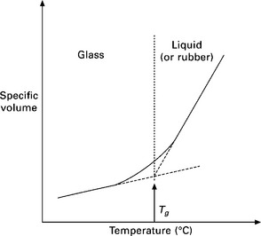
10.1 A typical graph of specific volume versus temperature for an amorphous thermoplastic (from Wise, 1999).
Semicrystalline thermoplastics are composed of crystalline regions and amorphous regions. For flow to occur in these polymers, their temperature must be above the crystalline melting point Tm, as shown in Fig. 10.2, which is the temperature at which all of the crystalline regions have disappeared (Stevens, 1953). Semicrystalline thermoplastics will generally have a Tg associated with the amorphous regions and Tm associated with the crystalline regions, with Tm > Tg. Viscous flow will generally only occur above Tm.
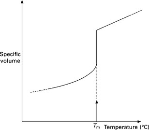
10.2 A typical graph of specific volume versus temperature for a semicrystalline thermoplastic (from Wise, 1999).
Thermal welding of thermoplastics relies on the temperature at the interface being above Tg for amorphous thermoplastics or above Tm for semicrystalline thermoplastics. Above Tm or Tg, there is increased chain mobility of the thermoplastic in the region of the weld. It is this increased mobility of the chains, which allows them to diffuse across the joint interface and entangle with chains on the other side of the interface. This is the mechanism for generation of strength at the joint and the formation of a weld between surfaces of similar thermoplastics.
10.3.2 Strength development at a joint: diffusion by reptation
A weld in a thermoplastic is generally formed when two pieces above their glass transition temperature or melting point are brought together for a period of time at temperature under sufficient pressure to ensure intimate contact at the joint interface. Based on this simple argument, early theories on welding were based around diffusion (Voyutskii, 1963). Molecular chains are said to diffuse across the interface and strength develops at the joint due to bridging by these chains (Fig. 10.3). Equations have been developed to account for the strength development as a function of time based on diffusion theory (Vasenin, 1961). The term ‘tack’ has been used to describe the build-up of mechanical strength at joints between similar and dissimilar materials. Tack at joints in similar materials is also sometimes called autohesion and was studied extensively by Voyutskii.

10.3 Scheme for polymer chains crossing an interface by diffusion leading to coalescence of two surfaces (from Voyutskii, 1963).
The main results of Vasenin’s derivation are that autohesion force for separation (F) has the following dependencies:
Or in combination, the force to separate two polymer surfaces is:
where t = time of contact, M = molecular weight, T = temp.
Following the work by Voyutskii and Vasenin, the next most significant advance in the theory of the welding of thermoplastics came from the development of reptation theory, which is important in explaining the development of weld strength.
The word reptation was originally coined by de Gennes (1971), from the Latin reptare (to creep), to describe the motion of polymer chains under certain circumstances. He first considered the snake-like movements of a linear polymer chain inside a strongly crosslinked polymeric gel. The gel provided a regular array of fixed obstacles through which the chain could not pass.
Instead the linear chain had to wriggle between the obstacles. The reason for this approach was that theories for the motion of polymer molecules in their molten state could not be made to agree with the experimental observations of viscosity and self-diffusion. De Gennes therefore simplified the problem to one linear chain moving in a crosslinked gel.
Amongst others, Wool developed the reptation theory into a model for welding. Wool’s theory for the welding of polymers has evolved since the late 1970s (Wool and O’Connor, 1980) and one incarnation involves dividing the welding operation into five stages (Wool and O’Connor, 1981):
Using the five identified stages of welding, Wool next defined a welding function W, such that the mechanical energy G required to separate two welded polymeric parts, was given by:
where W is a function of t = contact time, T = temperature, P = contact pressure and M = molecular weight. The general conclusions of the theory include:
10.4 Effect of main welding parameters
From reptation theory and experimental observations, the inferences summarised in Table 10.1 can be drawn in relation to the effects of the main welding parameters.
Table 10.1
Effect of plastics welding processing parameters
| High | Low | |
| Temperature | Fast weld Thermal degradation | Slow or no weld |
| Pressure | Chain diffusion inhibited | Insufficient surface wetting |
| Weld time | Oxidative degradation, flash | Insufficient diffusion, weak weld |
| Molecular weight | Very long weld times and high pressures required Slow diffusion weak parent materials and welds | Rapid weld times and low pressures required |
10.5 Modelling of plastics welding
Molecular simulation of plastics welding has been studied using a Monte Carlo model at the mesoscale, i.e. with detail of polymer chain motion, but not with atomic scale detail (Haire and Windle, 2001). The models described the polymer chain interdiffusion and could predict completion times for welds when surfaces were brought into contact at a temperature greater than Tg. The models were successful for linear amorphous polymers and there is suggestion that the theory can be extended to semicrystalline and/or branched polymers. More complex is the extension to all the commercial welding processes which can involve flow of the material and non-isothermal heating conditions in combination with chain interdiffusion. Figure 10.4 shows the output from a mesocale model of polymer welding after different periods of heating following contact of the two pieces.
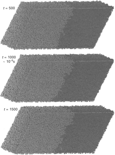
10.4 Simulation of polymer welding showing chain interdiffusion at a joint. (Haire and Windle, 2001).
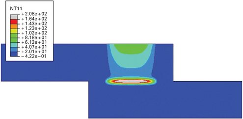
Thermal modelling of plastics welding (i.e. using heat flow considerations rather than chain interdiffusion) is applied most easily when the process is predominantly one of diffusion at the surfaces and has minimal melt flow, which complicates the heat flow calculations. Transmission laser welding is one such process. A finite element thermal model for transmission laser welding has been developed (Jones and Olden, 2000) and used to simulate the welding of thermoplastic polymers. Cooling rate curves generated experimentally and using finite element analysis have shown good agreement as have the weld dimensions measured and calculated.
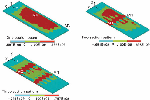
The model takes details of the materials’ radiation absorption coefficient, thickness, reflectivity, melting point, density, heat capacity and thermal conductivity. It also takes details of the laser source, including the laser beam profile, laser power and welding speed. Through analysis of the heat flow, it is possible to generate the thermal history for all points in the joint during the welding cycle. Thus it can provide the weld dimensions, the peak temperature and, with details of the materials’ mechanical properties, the residual stress remaining after welding can be estimated. Plate XI (between pages 328 and 329) shows a typical output from a finite element thermal model.
10.6 Introduction to plastics welding processes
Before considering the plastics laser welding methods, it is useful to review the other plastics welding methods available: techniques for thermally welding polymers can be broadly divided into three groups: those where heat is generated by mechanical movement of components to be joined; those where heat is generated by an external source and this source heats the joint by thermal conduction; and those using electromagnetism directly (Wise, 1999).
10.6.1 Techniques in which heat is generated by mechanical movement
When two surfaces are brought into contact and rubbed together under pressure, there is generally a temperature increase at the interface. The thermal welding of thermoplastics may most efficiently be accomplished by the generation of heat at the joint interface and for this reason welding techniques employing mechanical movement have found many commercial applications. The rate of temperature increase at the interface is generally related to the speed of the mechanical movement such that the greater the speed, the more rapid the temperature increase. High heating rates generally imply high welding rates and for this reason techniques where heat is generated by mechanical movement are often exploited in mass production. If the amplitude of vibration is small and correspondingly the frequency is high, then the methods become applicable to parts with small dimensions. Ultrasonic welding provides such conditions and is the only method in this group to be considered for microjoining applications.
10.6.2 Techniques employing a mechanical heat source
Thermoplastics generally have low coefficients of thermal conductivity particularly when compared to metals. This means that if heat can be applied to the joint area prior to joining, the temperature gradient normal to the surface may be high. However, in joining small parts, the loss of heat from the surface may be too rapid for the joint to be completed before cooling. Therefore methods where heating is carried out with the parts separated are normally only applied to large components. The only methods applicable to microjoining are hot bar or impulse welding, where the heat is applied externally to the parts as they are pressed together, and hot gas welding where a narrow gas stream may be used to provide a precise heating position to heat two small parts simultaneously.
10.6.3 Techniques which employ electromagnetism directly
The welding techniques which directly employ electric or magnetic fields are listed above. Although most thermoplastics exhibit dielectric (non-electrically-conducting) properties, they generally produce some response when excited by an electric or magnetic field at a certain frequency.
Heat is generated at the joint line by an electric or magnetic field or both. In some cases, the field heats the thermoplastic directly, e.g. dielectric (high frequency) welding, and in other cases the field heats a different material at the joint which in turn heats the thermoplastic, e.g. resistive implant welding.
Of these methods, only laser welding has found application for joints at small scale. This is as a result of the precise control available on the position and amount of energy applied by the process at the joint.
10.7 Polymer combinations that can be welded
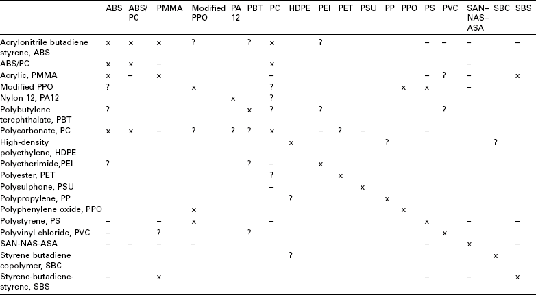
Only certain combinations of plastics are melt compatible and can be welded together. Generally the materials must have good miscibility, similar melting points and similar melt viscosities. Laser welding can provide a little more flexibility than other methods because the procedure can be completed rapidly without melting a large volume of material. Under these conditions, it becomes more feasible to combine materials with different melt properties. The combinations that can be welded are shown in Table 10.2.
10.8 Laser welding of plastics: process description
10.8.1 Introduction
The technique, suitable for joining both sheet film and moulded thermoplastics and textiles, uses a laser beam to melt the plastic in the joint region. Two general forms of laser welding exist: direct laser welding and transmission laser welding.
In direct laser welding, the materials are heated from the outer surface possibly to a depth of a few millimetres. Normally, no specific radiation absorber is added to the plastics. Laser sources from 2.0 to 10.6 μm wavelength are used. At 10.6 μm (CO2 laser) radiation is strongly absorbed by plastic surfaces, allowing high-speed joints to be made in thin films (Jones and Taylor, 1994; Coelho et al., 2000). At 2.0 μm, where the absorption is less strong, a fibre laser might be used to make welds in sheet a few millimetres thick. Direct laser welding is not widely applied for joining plastics. Alternatively, a beam with a large convergence angle can be used to make a weld where the beam intensity is high enough to melt material, and otherwise leave the material unaffected (Roesner et al., 2008).
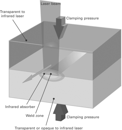
Transmission laser welding is widely used, and the bulk of the following discussion refers to this technique. Laser sources from 0.8 to 1.1 μm wavelength such as diode, Nd:YAG and fibre lasers are applied. The radiation at this wavelength is less readily absorbed by natural plastics without absorbing additives. Laser absorbing additives are put into the lower part or applied as a thin surface coating at the joint, so the parts can be positioned together before welding and the laser beam passes through the upper part to heat the joint at the absorbing surface of the lower part (Fig. 10.5). The absorber in or on the lower plastic is typically carbon or an infrared absorber with minimal visible colour (Clearweld) (Jones and Wise, 1998). These and other variations allow a wide range of part colours and appearances to be welded. Transmission laser welding is capable of welding thicker parts than direct welding, and since the heat-affected zone is confined to the joint region, no marking of the outer surfaces occurs.
10.8.2 Equipment and variations
10.8.3 Laser types for transmission laser welding
The main types of NIR laser used for through-transmission laser welding, and selected properties, are listed in Table 10.3. Additional details of each type of laser are given below.
Nd:YAG lasers
Nd:YAG lasers are widely used in industry for materials processing. Highpower systems are bulky, but lower power systems are relatively compact. Water-cooling is usually required. The beam is transferred from the laser to the workpiece via an optical fibre. It is feasible to combine the beam from more than one laser to produce higher powers if required. The high beam quality allows a relatively small spot size to be produced if required for precision welding. Focused spot sizes of less than 50 mm are available for sources with power greater than 10 W if required.
Diode lasers
Diode lasers produce radiation at a wavelength of 808 nm (InGaAlAs) or 940 nm (InGaAs). Water-cooling is usually required. Their relatively low beam quality means that they cannot be used to produce spot size as small as Nd:YAG or fibre lasers. However, this is rarely a problem for plastics laser welding, where the relatively low purchase and running costs have attracted a great deal of interest. The beam may be delivered by an optical fibre, but the diode laser is sufficiently small and light that it is often feasible to use a direct system, in which the diode is included with a lens system in a single unit, typically ~ 150 × 150 × 300 mm. This unit can be readily mounted on a gantry system or robot arm to manipulate the beam.
Fibre lasers
Rare-earth-doped fibre lasers typically supply a single wavelength in the range 1,000–2,100 nm. In the field of materials processing, much interest has focused on wavelengths around 1,100 nm to provide a direct replacement for Nd:YAG lasers, with equivalent beam quality, but greater efficiency. Systems are relatively compact and can be air-cooled. In the field of plastics welding, the use of fibre lasers has been demonstrated for a range of applications, including precision welding, films, textiles and larger moulded parts.
10.8.4 Manipulation equipment
The beam or workpiece manipulation equipment for laser welding will take one of the following forms as illustrated in Fig. 10.6 and described in more detail below.
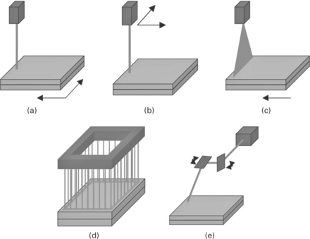
10.6 Welding methods (from Warwick and Gordon 2006): (a) moving workpiece; (b) moving laser; (c) curtain laser; (d) simultaneous welding; (e) scanning laser.
Moving part
With the laser fixed, the part can be manipulated to form a continuous weld. This can be achieved, for example, with rollers, or a single- or two-axis moving table. This type of system is relatively simple to set up and program. It would not normally be used if three-dimensional welds are required.
Moving laser
The optical system for a fibre delivered laser, or the laser head for a direct diode laser, can be mounted on a variety of robotic systems. These range from simple two-axis gantry systems to multiple-axis robotic arms. The laser is then manipulated around the part to be welded, potentially allowing complex, three-dimensional welds to be produced. To facilitate automatic production, it is feasible to combine a moving laser with a moving part, for example by using a rotating table to present different faces of a component to a laser mounted on a robot arm. The resolution is limited by the size of the laser beam which could be as small as 10 microns.
Curtain laser
The laser energy is spread into a line and then passed over the component, either by moving the laser or by moving the part. A mask is typically used to ensure that only the relevant areas of the component are exposed to the radiation. This is particularly suited to small components with a complex weld geometry. The process would usually be used only to produce two-dimensional welds. The welds are completed very quickly with a single sweep of a line source, but the resolution is limited to around 100 microns.
Simultaneous welding
If a large number of identical welds is required, then an array of diode lasers can be assembled in the shape of the weld. This is then used to irradiate the whole joint simultaneously, with a typical cycle time of 1–3 s. This approach is well suited to automated assembly. The equipment used is frequently based on ultrasonic welding equipment, and this process is typically used in place of ultrasonic welding where a good cosmetic appearance is required or for components that are sensitive to vibration. Two- and three-dimensional welds can be produced. The entire joint is welded at the same time, allowing more collapse of the polymer at the joint, and therefore allowing wider part tolerances.
Scanning laser
The laser radiation is manipulated by a pair of orthogonal rotating mirrors over an area that may range from 50 mm × 50 mm up to approximately 1000 mm × 1000 mm. In general, a larger working area implies a longer working distance and a larger spot size. It is possible to co-ordinate an assembly of a number of scanning systems to give a larger working area. In general, only two-dimensional welds can be produced.
Repeatedly scanning the laser at high speed over the same path can be used to give quasi-simultaneous welding. As for simultaneous welding, this welds the entire joint area at the same time, allowing more collapse of the material in the joint and potentially allowing wider tolerances.
10.8.5 Clamping systems
A wide variety of clamping systems have been used for through-transmission laser welding. They are mostly variants of the two systems illustrated in Fig. 10.7.
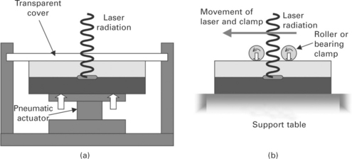
10.7 Clamping systems for through-transmission laser welding (from Warwick and Gordon, 2006): (a) fixed clamp; (b) moving clamp.
Variants of the fixed clamp include systems using mechanical fastenings, rather than an actuator, to apply a load. In the simplest variant, if the part design allows it, a bolt can be passed through the workpiece to apply the load. The transparent cover must be rigid enough to provide the clamping pressure. Thick acrylic or plain plate glass can be used. Borosilicate glass is less vulnerable to thermal shocks during welding, but more expensive. For welding of high-temperature polymers, quartz glass may be used. In all cases, it is important to ensure that suitable safety precautions are taken to avoid the risk of injury if the transparent cover breaks while it is under load.
The moving clamp can use bearings, rollers, or a simple sliding shoe to apply a clamping load. Because the load is applied only at the point where the joint is irradiated, clamping loads may be much lower when a moving clamp is used. There is therefore less risk of distorting the workpiece, and equipment can be less bulky. This is particularly advantageous for large components, where application of a suitable clamping pressure to a large area can require large loads.
10.8.6 Monitoring and control methods
Although several commercial imaging techniques, such as infrared, ultraviolet, ultrasonic and visible light imaging are available (Jones and Rudlin, 2006) for viewing welding phenomena in metals and plastics, the transmission laser welding process poses a unique challenge, whereby the weld interface is typically behind two layers of polymer sheet: the pressure transmitter sheet, typically made from poly(methyl methacrylate) (PMMA), and the top layer of the part to be welded. Any top face monitored image of the weld region must therefore pass through these two layers. In addition, methods using IR absorbing coatings are designed to have minimal visible impact, making some monitoring methods difficult to use. Low colour IR absorbers can also be used in the resin of the lower part in a similar way to the normal use of carbon black absorber. Monitoring methods needed for this case are different again compared to use of IR coatings.
Visible light imaging is appropriate when transparent and translucent materials are used as the top layer. It is a low-cost option that uses off-the-shelf equipment. However, this method would be unsuitable when visibly opaque materials are used as the top layer.
Thermographic techniques remotely measure the radiation emitted from a hot surface by virtue of its temperature. The temperature of the surface can be calculated from the spectrum and intensity of the radiation emitted. The strength of the signal available is the product of the spectral radiance and the material’s emissivity at a given wavelength. Emissivity values range from 1.0 for lampblack down to 0.02 for polished silver. Thermography is used effectively for monitoring laser welding in real time, providing a temperature measurement. This technique is regularly used to control the laser power to keep the process within a pre-defined range of temperatures and can indicate when and where problems have occurred if the temperature goes outside the acceptable range.
Infrared imaging is carried out in the same way as visible light imaging, with cameras sensitive to the near infrared range of wavelengths. In principle, if wavelengths of the thermal emission spectrum from the weld are used, then a thermal picture of the weld can be seen. A method of using an IR camera to image a complete weld line immediately after the welding process has finished has been described when welding clear to black polycarbonate parts. Regions of differing temperature could be identified and could indicate variations in weld quality along the joint.
Spectroscopic transmission measurements are used to measure the absorption properties of the IR absorber and substrate materials over a range of wavelengths. This procedure may be used before and after the coating deposition to check the position and amount of absorber present. As a result of the laser heating, some or all of the dye decomposes during the welding process into products that have a different absorption signature. Measurements made using a spectrophotometer before and after welding can therefore reveal information about the heat generated during welding.
Monitoring may be applied for a number of reasons, both assessing that various stages of the process have occurred, as well as indicating the quality of the weld:
• Check infrared absorber is applied correctly to parts before welding.
• View of weld during process.
• Indication that parts are in contact during process.
• Indication that weld heating is being carried out and control of temperature.
• View of weld after completion.
• Indication that parts are in contact after completion.
• Indication that weld has been achieved after completion.
• Indication that weld quality and strength are satisfactory.
Monitoring methods can give information for most of these points with varying degrees of confidence. However, it must be noted that a complete quality and weld strength assurance can only be achieved with destructive testing.
10.9 Welding parameters
As with all plastics welding processes there are three critical process parameters: temperature, time, and pressure.
The energy density used during welding combines the process parameters of temperature and time. It is determined by the laser power, the spot size at the joint, and the irradiation time (for fixed processes) or welding speed (for processes in which the part moves with respect to the laser):
If the energy density is too low, then insufficient heating takes place and the material at the joint is not held at a high enough temperature for a sufficiently long time to form a strong weld. If the energy density is too high, then excess heating can degrade the polymer at the joint, resulting in porosity, or, in extreme cases, burning or charring of the polymer. Either case results in a weld of lower strength than the optimum. In practice, a relatively wide processing window can usually be found within which satisfactory welds can be produced. Typically, laser welding applications use an energy density within the range 0.1–2 J/mm2, although this will vary depending on the depth of melt required to ensure a satisfactory joint. Although the energy density can be used to characterise the welding process, it should be treated with caution. The conduction of heat away from the joint during welding means that using the same energy density will not necessarily result in the same quality of weld. For example, with a constant spot width, doubling the power will usually allow the speed to be more than doubled, whilst retaining the same performance from the weld.
The pressure applied is controlled using the clamping system. If the workpieces are not clamped together during welding, or if the pressure at the joint is insufficient, then the joint faces will not be in intimate contact. This results in:
• poor conduction of heat to the upper workpiece
• limited interdiffusion of polymer chains on either side of the joint.
Both effects result in a weld of lower strength than the optimum. Care is needed to ensure that a clamping load actually provides pressure at the joint. Typically, clamping pressure in the range 0.1–1 N/mm2 is used. If the workpieces bend under the clamping load in such a way that the joint is distorted, then a poor weld can result. For this reason, it is often useful to have some compliance, for example an elastomeric element, in the clamping system.
10.10 Advantages and disadvantages of transmission laser welding
10.10.1 Advantages
10.10.2 Disadvantages
• Expensive compared to other plastics welding equipment
• Joint surfaces must be of good quality
• Part clamping must be designed carefully to ensure contact at the whole of the joint area during welding
• Laser absorbing material must be added to one of the plastics or at the joint surface
• The top part must transmit the laser radiation. This can limit the thickness of the top substrate when welding plastics with low transmission (e.g. PEEK or some filled plastics).
10.11 Applications
Transmission laser welding is used in a wide range of plastics joining application areas, including:
10.12 References
Coelho, J. P., Abrea, M. A., Pires, M. C. High speed laser welding of plastic films. Optics and Lasers in Engineering. 385–395, 2000.
De Gennes, R. P. Reptation of a polymer chain in the presence of fixed obstacles. Journal of Chemical Physics. 1971; 55(2):572–579.
Haire, K. R., Windle, A. H. Monte Carlo simulation of polymer welding. Computational and Theoretical Polymer Science. 2001; 11(3):227–240.
Jones, I. A., Olden, E. A thermal model for transmission laser welding of thermoplastic polymers. TWI Members report 708/2000. (July):2000.
Jones, I., Rudlin, J. Process monitoring methods in laser welding of plastics. Conference Proceedings Joining Plastics. 2006:25–26. [April 2006, London. ].
Jones, I. A., Taylor, N. S. ‘High speed welding of plastics using lasers’, ANTEC ‘94 Conference Proceedings, 1–5 May 1994. CA: San Fransisco; 1994.
Jones, I. A., Wise, R. W. Welding method. Patent application WO 00/201587, 1. (October):1998.
Jones, I. A., Hilton, P. A., Sallavanti, R., Griffiths, J. Use of infrared dyes for transmission laser welding of plastics. ICALEO, November: Proc; 1999.
McCrum, N. G., Buckley, C. P., Bucknall, C. B. Principles of Polymer Engineering. Oxford: Oxford University Press; 1988.
Puetz, H., Haensch, D., Treusch, H., Pflueger, S. Laser welding offers array of assembly advantages. September: Modern Plastics International; 1997.
Roesner, A., Abels, P., Olowinsky, A., Matsuo, N., Hino, A. Absorber-free laser beam welding of transparent thermoplastics. Conference Proceedings ICALEO. 2008; 2008:105–111.
Silvers, H. J., Jr., Wachtell, S. Perforating, welding and cutting plastics films with a continuous CO2 laser. Proc. PA State University, Eng, 1970:88–97. [August. ].
Stevens, M. P. Polymer Chemistry. Ithaca, NY: Cornell University Press; 1953.
Toyota, Jidosha K. K. Laser beam welding of plastic plates. Patent application JP85213304, 26. (September):1985.
Vasenin, R. M. The sticking pressure in the diffusion theory of adhesion to polymers. Vys. Soed.. 1961; 3(5):679–685. [Rapra Translation 1010 by R Moseley, 1962. ].
Voyutskii, S. S. Autohesion and Adhesion of High Polymers. New York: John Wiley and Sons; 1963.
Warwick, C. M., Gordon, M. Application studies using through-transmission laser welding of polymers. Proc. Joining Plastics. 2006; 2006:25–26. [April 2006, NPL, London. ].
Wise, R. J. Thermal Welding of Polymers. Cambridge: Woodhead Publishing; 1999.
Wool, R. P. Polymer Interfaces: Structure and Strength. Munich: Carl Hanser Verlag; 1995.
Wool, R. P., O’Connor, K. M. Craze healing in polymer glasses. ACS Polymer Preprints. 1980; 21:40.
Wool, R. P., O’Connor, K. M. A theory of crack healing in polymers. Journal of Applied Physics. 1981; 52(10):5953–5963.
This chapter is a revised and updated version of Chapter 22 ‘Plastics Microwelding’ by Ian Jones, originally published in Microjoining and Nanojoining edited by Norman Zhou, Woodhead Publishing Limited, 2008, ISBN 978-1-84569-179-0.


