Defect formation mechanisms and preventive procedures in laser welding
Abstract:
This chapter deals with the terminology, characteristics, formation conditions, causes, occurrence mechanisms and preventive procedures or measures of laser welding defects or imperfections. In particular, porosity and solidification cracking are described in detail in conjunction with laser welding phenomena.
12.1 Introduction
Laser welding can join parts together at very fast speeds or produce deep-penetration welds efficiently in any environment such as air, shielding gas or vacuum. Consequently, it is known as a high-quality, high-precision, low-distortion, low-deformation, high-efficiency, high-performance, high-flexibility and high-speed joining process. It also facilitates robotization, automation, saving manpower, systematization, etc. Accordingly the applications of laser welding in many industrial fields are increasing together with the development of carbon dioxide (CO2) laser, YAG laser, diode laser (LD), LD-pumped solid-state laser, disk laser and fiber laser of high power, high efficiency or high quality. However, welding imperfections or defects leading to a fracture or a disaster of manufactured goods or constructions may take place under improper conditions. In order to manufacture sound goods or constructions of high quality and high reliability with a laser beam, it is inevitably important to establish preventive procedures for welding defects and to take the necessary measures on the basis of understanding of welding phenomena as well as their formation conditions and mechanisms.1
In the following sections, the formation mechanisms and preventive measures of laser welding defects or imperfections are reviewed. In particular, the formation mechanisms and preventive procedures of porosity and solidification cracking will be described in detail together with laser welding phenomena.
12.2 Terminology, characteristics, causes and preventive procedures of laser welding imperfections and defects
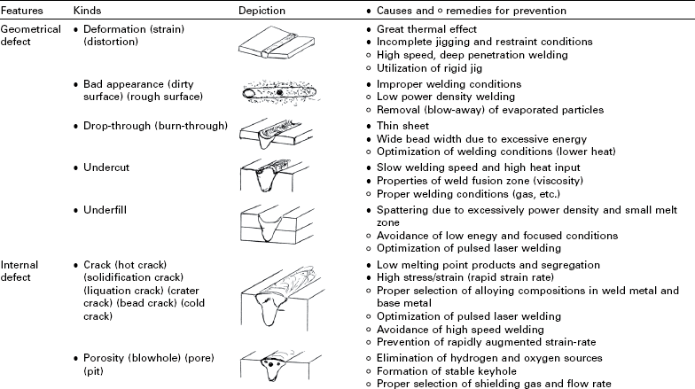
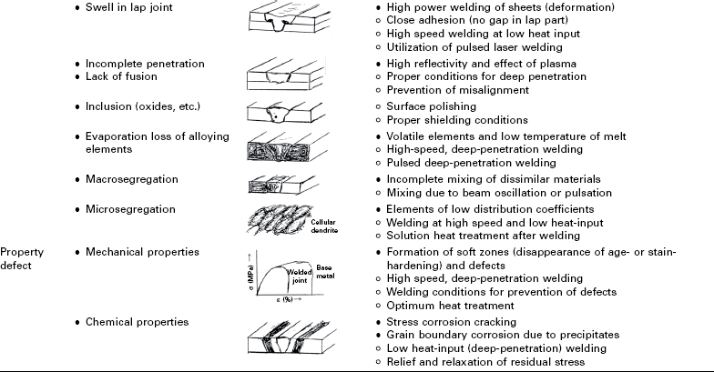
In laser welding, a variety of defects or imperfections may occur depending on the kinds of material and their compositions, welding conditions, and so on. Laser welding defects are classified into three characteristic groups: geometrical or appearance defects, internal or invisible defects, and property or quality defects1,2 (which are modified from arc welding defects3). The kinds, features, schematic representation, causes and suppression or prevention procedures of the main laser welding defects are summarized in Table 12.1.1,2 In laser welding, porosity is easily formed in deeply penetrated welds, characterized by high-power laser welding. Solidification cracking and liquation cracking may occur in laser weld fusion zones and the heat-affected zone (HAZ), respectively, in aluminium alloys, Ni-base alloys, etc. Such internal defects result in degradation in mechanical properties or may cause a catastrophic-failure, and their detection is sometimes difficult. Therefore, porosity and solidification cracking, which should be prevented, will be described in further detail in the other sections.
Table 12.1
Kinds, features, schematic representation, causes and suppression or preventive procedures of main laser welding defects
12.2.1 Geometrical or appearance defects
Laser welding deformation or distortion
During laser welding, the metal or material is subjected to thermal cycles or histories, such as heating, melting, evaporation, solidification and cooling, and is inevitably accompanied by volume changes of thermal expansion and contraction. This causes distortion or deformation, residual stresses, or even cracking in the welded joint.
Welding deformation and/or distortion should always occur. In thin plates or sheets and various manufactured goods of the materials such as aluminum alloys and austenitic stainless steels with great thermal expansion coefficients, welding deformation or distortion takes place easily. It occurs more appreciably in the case of larger heat inputs, a larger welding molten pool, and a greater difference between the upper and lower bead widths. Angular deformation and/or lateral contraction distortion happens in thick plates, and warping such as angular deformation, longitudinal distortion and buckling deformation occurs in thin sheets.4 Solidification cracking may take place due to rotary deformation during welding near the edge or the end of thin plate.1
As suppression procedures for welding deformation or distortion, the following measures are considered:
• the use of rigid fixture or jig,
• rapid cooling or quenching of the welded part and its vicinity just after the molten pool,5
• keeping the welded products cooled to room temperature in the fixture,
• formation of a parallel full-penetration weld bead (that is to say, almost the same weld bead widths in the penetration depth direction), and
In addition, the deformation and/or distortion is much smaller in laser welding than in any other fusion welding, since the heat input and bead width of a laser weld are generally smaller and narrower, respectively, than those of any other welding process.6
Poor surface appearance of laser welds
Poor surface appearance of laser or hybrid laser-arc welds is caused by oxidation, the deposition of ultrafine particles, fumes and debris, and/or rough surfaces due to spatters, pits, humps, underfills, undercuts, etc. (These technical terms will be described in detail in later section.1) The surface of a laser welded part and its vicinity is exposed to high temperatures during laser welding, and therefore a shielding gas is used to protect a molten pool and the surrounding part from oxidation. Nevertheless, the surface is oxidized or suffers from deposition of ultrafine particles produced by evaporation or spatters of melt particles. The color of the surface may be changed from metallic silver to purple, dark blue and black, golden or white depending on the oxidization levels in stainless steels or titanium alloys. Spattering results in the deposition of spatters on or near the weld beads and the formation of concave bead surfaces,7 which are judged to be poor surface appearances. Pits or rough surfaces are observed in the weld beads of cast alloys enriched with segregated inclusions or hydrogen sources, Zn-coated steel lapped sheets or some alloys produced under improper conditions.
To counteract poor surface appearance of welds, the respective proper measures should be taken by considering their causes:
• In the case of the deposition of ultrafine particles or evaporated particles and oxidation, a proper amount of an inert shielding gas (for example, Ar, He or N2) should be flowed from the optimum direction.8
• In the case of laser-arc hybrid welding of aluminum alloy, a weld bead made under the condition of laser-leading and arc-following exhibits a better surface appearance than that of arc-leading and laser-following because of the surface cleaning action of an arc.9
In order to suppress spattering in bead (melt-run) welding with CW (continuous wave) lasers, the following measures may be recommended:
• The adoption of beam-defocused conditions or heat-conduction welding.
• The adoption of an extremely small beam spot in comparison with the molten pool size.
• The enlargement of a keyhole inlet by a proper flow of a shielding gas.
• The utilization of pulse-modulated mode with power decrease before the occurrence of spattering instead of CW mode.
• The use of minus defocused conditions (setting a focal point below the specimen plate surface) in high power laser welding.
In the case of laser welding of zinc(Zn)-coated steel sheets, a proper gap (e.g., 0.05–0.3 mm) between sheets should be employed to reduce the detrimental effect of the Zn vapor against the molten pool, although no gap at all is normally used in laser welding of other metals.
In spot welding with a PW (pulsed wave) laser, spattering takes place due to a small tolerance of a melt around a keyhole when the keyhole is formed in a small molten puddle. Therefore, to suppress spattering in spot welding, a relatively larger molten pool should be formed, and the (peak) laser power density should be increased gradually so as to slowly deepen a keyhole.
Burn-through or melt down
Burn-through is the phenomenon where the melt in a molten pool is dropped down during welding to form an underfilled bead with concave top surface and convex bottom surface. Burn-through occurs easily in the case of full penetration welding of a thin sheet or a thick plate with wide bottom surface of a molten pool at high heat input.1 It happens more readily in materials with lower surface tension. In the case of a thick plate of steel or stainless steel with a higher surface tension at a lower temperature, noticeable humping on the bottom surface takes place if the laser power is not so high as to produce a full penetration weld with a low content of oxygen with a through-keyhole.10,11 Figure 12.1 shows examples of a sound full penetration weld bead and a poor one with humps on the bottom surface in HT 780 steel plate of 12 mm thickness, observation results of a molten pool on the top and bottom surfaces during 10 kW fiber laser welding with a hot wire, and the mechanism of the formation of underfilling and bottom humps.11 In the weld metal with an appropriately high content of oxygen, bottom humping is prevented. The melt at lower temperatures near the bottom rear end of the molten pool with a low content of oxygen has such a high surface tension to pull the higher temperature liquid near the keyhole tip, resulting in the formation of bottom humps.11 It is noted that surface tension and its gradient may affect melt flows and the formation of welding defects.
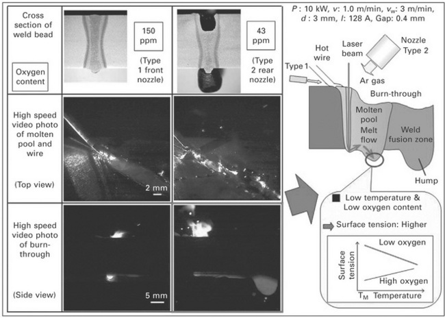
12.1 Cross sections of weld beads and video observation results of molten pool from back-upper and horizontal sides during welding of butt joints of 12 mm thick HT 780 steel plates with 0.4 mm gap subjected to fiber laser welding with hot wire at 10 kW and 3 m/min in Ar shielding gas by using Type 1 and Type 2 nozzle, showing sound full penetration weld bead and underfilled bead with humps on the bottom surface, and schematic formation mechanism of underfilling and bottom humps, showing melt flows due to effect of surface tension considering temperature and oxygen content.
To prevent the burn-through or melt down, the welding conditions should be optimized. The use of a hot wire and a proper content of oxygen in a molten pool should prevent bottom humping in laser welding of thick steel plates.10,11 The use of a backing plate or a shielding gas to suspend the bottom molten pool surface may be required as a preventive measure against burn-through.
Undercutting
Undercut is the name for a groove along the toe of the weld bead. Examples of a sound laser weld bead and poor ones with underfill or undercut in 3 mm thick AZ31 alloy plates are shown in Fig. 12.2.12 Undercutting is likely to occur in a wide bead made with a high power laser, at high pressure of an assist gas or under a large amount of flow of shielding gas from the front side of welding. In laser-arc hybrid welding, undercutting may occur easily in full penetration weld bead made at high arc current. A high arc current must induce shielding gas and plasma flows backward. In the case of fillet welding for a T-joint, an undercut is easily formed in the vertical plate. The cause is attributed to the effect of gravity which causes the upper melt in the molten pool to sag.
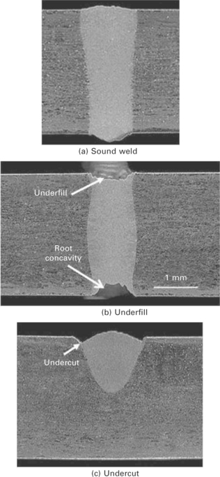
12.2 Examples of (a) sound weld bead, (b) underfilled weld bead and (c) weld bead with undercuts produced by disk laser welding of 3 mm thick AZ31 alloy plates in Ar shielding gas.
The optimization of welding conditions is needed as a measure to prevent undercutting. In hybrid welding, an additional filler wire may prevent undercutting.
Underfilling
Underfilling is the name for a concave surface of a weld bead, as shown in Fig. 12.2(b).12 It occurs when welding the butt-joint with a wide gap with a shortage of filler wire, in the case of full penetration weld accompanied with burn-through,10 or severe spattering of melts.7,12
Underfilling is suppressed or prevented by beam-scanning, utilization of a filler wire, or hybrid welding (with additional filler wire for a wider gap13) under the proper conditions.
In the case of lap welding of Zn-coated steel sheets without gap, spattering occurs very easily due to evaporation of the Zn layer, resulting in the formation of underfilling.14 In this case, control of the gap between sheets is needed.14,15 In spot welding, when a high power density laser is shot rapidly, spattering takes place due to a keyhole formation because of a small tolerance of melt in the molten pool, leading to a underfilled weld. In such a case, the optimization of welding conditions such as slow increase in laser power or energy is required.16
Reinforcement of weld or overlapping
Reinforcement of a weld may be formed in the case of welding with the excessive amount of a filler wire or with high power density laser with a small beam size at higher welding speed.7 It is well known that fatigue properties of the toe of the weld are degraded. Therefore, the reinforcement of a weld may be removed to improve the fatigue properties of a welded joint.
Overlapping occurs due to the overflow of a melt on the base metal, and it may take place in fillet welding with a filler wire. The means of optimization of filler wire supply and sufficient melting of metal are needed.
Humping
Humping, which means the periodical formation of humps of weld metal on the bead surface, may occur in a narrow weld bead produced with a very small focused beam during high speed welding7 or during low vacuum welding at a focal point.17 Examples of humping and preventive conditions are shown in Fig. 12.3.7 Humping is formed owing to the backward flow of a melt ejected by plume ejection and the high surface tension of the accumulated melt due to a narrow molten pool width.7
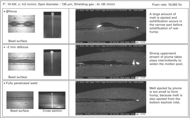
12.3 Surface appearances and cross sections of weld beads and video observation pictures during welding, showing examples of humping (upper), and suppressed humping due to defocused conditions (middle) and full penetration welding (lower).
Such humping may be suppressed under the conditions of defocused distances (a focal point below the plate surface leading to wider molten pool surface) or by changing partial penetration to full, leading to the suppression of a melt ejected upward, as shown in the middle and lower parts of Fig. 12.3, respectively.7
12.2.2 Internal or invisible defects
Hot cracking (solidification cracking and liquation cracking)
Hot cracking (or high temperature cracking) in the weld fusion zone and the HAZ is called ‘solidification cracking’ and ‘liquation cracking’, respectively. Examples of such cracking in laser-welded A2090 aluminum alloy are shown in Fig. 12.4.3,18 In aluminum alloys, fully austenitic stainless steels, Ni-based alloys, etc., solidification cracking and liquation cracking may occur along grain boundaries. In particular, solidification cracking can occur easily during spot welding with a pulsed laser or during high speed welding with continuous wave (CW) laser.2 These causes are attributed to microsegregation and resultant formation of low solidification temperature liquid films along the grain boundaries, and thus the selection of proper materials and the process to reduce tensile load or strain during welding are important.1,2 In the case of spot welding with a pulsed laser, the irradiation conditions of tailing laser power so as to narrow the area of a mushy zone (coexistence of solid and liquid) should be preferably selected to suppress solidification cracking.16,19
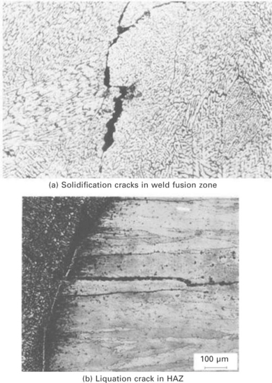
12.4 Examples of solidification crack in laser weld fusion zone (a) and liquation crack in HAZ (b) of A2090 alloy plate.
In mild or high tensile strength steels, hot cracking or pear-shaped cracking may take place near the middle or bottom part of a partially penetrated deep weld bead made with high power laser17 or laser-arc hybrid. The causes may be ascribed to the formation of retained liquid areas due to melt flows near the bottom part of the laser or hybrid weld beads.17 The optimization of weld penetration depth or bead geometry or the selection of a filler wire is recommended.
In welding of dissimilar materials, hot cracking occurs very easily if a large amount of intermetallic compound is formed.20 In this case, the area of the intermetallic compound should be minimized by controlling the mixing of a molten metal of dissimilar materials. It is important to suppress the melting area in the lower plate at high welding speeds.
Cold cracking
Cracking which occurs below 300 °C is generally called ‘cold cracking’.3 In general structural steels and low-alloyed high tensile strength steels, cold cracking known as ‘delayed cracking’ or ‘hydrogen-assisted cracking’ may take place due to the harmful effect of hydrogen accumulated in the highly stress-concentrated zone,21 while in the case of medium and high carbon steels, ‘quenching cracking’ or ‘restraint cracking’ may occur due to the formation of brittle martensite and/or cementite during welding. Cold cracking is affected by hydrogen content in the weld, restraint stress and the formation of hard martensite phase, and occurs in a shorter period under conditions of higher hydrogen content, higher restraint stress and/or higher hardness of the weld.
Cold cracking may be prevented by pre-or post-heating treatment similar to the other welding processes.21 Nevertheless, laser welding or hybrid welding can be performed in the high tensile strength steels at room temperature without pre-or post-heating because of low hydrogen content in the weld metal.22
For high carbon steels and cast iron, quenching cracking is easily generated, and so the pre-or post-heating treatment, slow cooling of a weld or the use of a Ni-enriched wire is recommended to prevent cracking.23
Porosity
Porosity refers to blowhole, pore, wormhole, pit or bubble. In this chapter, porosity and bubbles are used in the ‘solid’ weld fusion zone and the ‘liquid’ molten pool, respectively.1,2
Porosity is very easily formed during laser welding. In the keyhole type of deep penetration welding, the majority of bubbles, which are generated from the tip of a keyhole during welding, lead to the formation of porosity in the weld fusion zone. Porosity formation is affected by the surface cleanness of the butt-joint, the kind of shielding gas, and welding conditions.1,2
The suppression or prevention procedures for porosity are:
• keyhole laser welding under the proper conditions (for full penetration),
• welding with a shallow, stable keyhole or heat-conduction type welding,
• low or high vacuum laser welding,
• forward welding with an inclined laser beam,
• welding under the properly defocused conditions (for the formation of a conical, stable keyhole),
• the selection of a proper shielding gas for the material, and so on.1,2
In aluminum alloys, especially, the cleaning of butt-joint or lap-joint surfaces is needed to remove oxide films and hydrogen sources. In spot welding with pulsed laser, a part of a keyhole is retained as porosity in the middle or bottom part of the weld metal due to the rapid collapse of the keyhole.2,16,24 To prevent such porosity, the control of laser power (or its density) or the selection of proper pulse waves in the final stages of laser irradiation is required.2,16,24
In cast or die-cast alloys, porosity is formed by the enlargement of the origins of bubbles in the base materials.25,26 Thus it is difficult to prevent such bubbles. It may be slightly reduced by the use of an intermediate (insert) sheet or a filler wire.26 In laser welding of Zn-coated steel sheets, a proper degree of gap between the sheets is required to prevent porosity.
Spiking
Saw-like penetration with periodical variation may be formed near the bottom part of a partially penetrated weld bead made with CO2 laser, LD-pumped YAG laser, disk laser or fiber laser with a high power and high density under the defocused conditions of large minus values.8,27,28 This is called ‘spiking’ or ‘spiking phenomenon’. Welding defects called spiking porosity, root porosity and cold shut occur in deep weld metal parts of spiking. In order to prevent such defects, a defocused beam (of focal point above the plate surface) with reduced power density, beam scanning, and tandem beam welding can be applied.
Swelling of lap weld
Swelling may take place in thin aluminum alloy sheets subjected to low welding speed and high heat input. It is also observed in a pulsed YAG laser spot weld of 0.1 mm thick upper sheet onto 1 mm thick lower sheet of aluminium alloy.2,29 It is especially present in the case of a larger amount of melting in the upper sheet in comparison with the lower plate. Some measures such as use of a strong restraint to prevent deformation or distortion of the upper sheet, improvement in thermal conductivity or heat transfer of the upper and lower sheets, the reduction in heat input, and re-melting treatment of the upper part of swelling are effective.
Incomplete penetration, incomplete fusion or lack of fusion
Incomplete penetration of a weld bead accompanied with the change from a keyhole type of deep penetration to a conduction type of shallow penetration may take place easily in the material with high reflectivity and high thermal conductivity such as aluminum alloys and copper alloys.2,28,30 Such a change may be caused by argon (Ar) plasma in CO2 laser welding in addition to the material properties of high light reflection and high heat conduction. To prevent this, the use of helium (He) shielding gas or a laser with about 1 μm wavelength is needed. The lack of fusion may be observed in the case of multi-pass deep welds in a narrow gap with a filler wire. To prevent this lack of fusion in multi-layers, beam scanning method, higher laser power or a smaller amount of deposited layer are considered to be effective.
Inclusions
Inclusions such as oxides or nitrides are formed in the case of oxidized plate surface or butt-joint surfaces, or welding with an active shielding gas such as O2, N2 and CO2. Oxides are sometimes detrimental to ductility in the weld of martensitic steel and austenitic stainless steel, but have a beneficial effect on the ductility by forming embryos for ferrite phase formation in the steel weld fusion zone.31 It is known that nitrides, which are formed at high temperatures in the molten pool, are effective in reducing solidification cracking by the presence across the grain boundaries in A6xxx aluminum alloy.32 To reduce inclusions, the plate surfaces and butt-joint surfaces must be cleaned, and laser welding should be performed in the appropriate shielding gas conditions.
Evaporation loss of alloying elements
Evaporation always occurs during laser welding, and the contents of impurity or volatile alloying elements with low vaporization temperatures (e.g., Mn in Fe, and Mg, Zn, Li, etc. in Al) decrease by a higher amount of evaporation than the base metal.2,30,33 Evaporation loss should be reduced by welding at high speed or compensated by using a filler wire with a higher content of alloying elements.
Macrosegregation
Macrosegregation is present in the weld fusion zone in the case of laser welding of dissimilar materials20 or using a filler wire different in chemical composition from the base metal.23 Mixing or steering of melt in the molten pool can reduce macrosegregation. The cross section and schematic of a laser weld, EDX analysis results of Fe and Ni elements and line analysis results of Fe and Ni along the bead centerline are shown in Fig. 12.5, where laser welding was performed for a butt-joint of 0.4 mm gap between cast iron and low carbon steel plates using a 97%Ni filler wire.23 In laser welding, sufficient mixing of a filler wire into the base metal is difficult, and consequently the compositions of the bottom part of the weld fusion zone are approaching those of the base metal.23’34 The wider the gap in the butt-joint, the more deeply the compositions of the filler wire reach.23
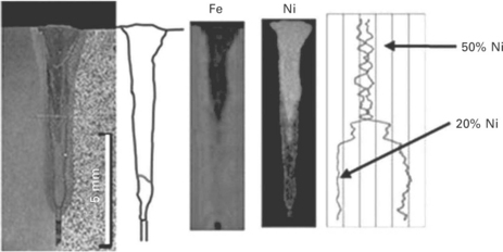
12.5 Cross section and schematic of laser weld made in butt-joint of cast iron and low carbon steel plate with 0.4 mm gap using 97%Ni filler wire, EDX analysis results of Fe and Ni elements and line analysis results of Fe and Ni along bead centerline, showing enrichment of Ni in upper part of weld fusion zone.
Microsegregation
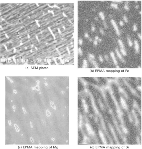
Microsegregation necessarily occurs due to the solidification process in fusion welding (such as arc, plasma, laser and electron beam welding) of alloys.1,2,35 An SEM photo of the laser weld fusion zone in A6061 aluminum alloy, and EPMA analysis results of Fe, Mg and Si of some areas are shown in Fig. 12.6.33 EPMA and EDX analysis results can reveal microsegregation of Fe, Mg and Si along cellular dendritic boundaries and the same enrichment of Mg and Si at the partial cell boundaries. White phases in the SEM photo correspond to the microsegregation of Fe (of higher density). Thus the microsegregation takes place more easily for an alloying element or an impurity with a smaller distribution coefficient and at a higher content.35 As a result, the solidification temperature of the melt falls during solidification, leading to the occurrence of solidification cracking and degradation in the strength of the weld joint.36–38 In the case of age-hardenable alloys, aging recovery is insufficient due to lower contents of chief aging elements near the cell cores.37 To prevent the reduction in hardness and strength due to microsegregation, solid solution heat treatment of the joint after welding is effective.
12.2.3 Quality or property defects
Reduction in mechanical properties
In the case of normal carbon steels, the welds are hardened due to the formation of harder phases such as lower bainite and martensite, and the strengths of the joints are generally higher than those of the base metals.39 On the other hand, in the case of quenched and tempered high tensile strength steels, and age-hardenable or work-hardenable materials such as aluminum alloys, Ni-base alloys and copper alloys, the hardness or strength of the weld fusion zone and HAZ becomes lower than that of the base metal.30,33,37 The tensile strength results of welded joints of various aluminum alloys are shown in Fig. 12.7. In the annealed base alloys such as A5052, A5083 and A5182, the strengths and strains of the joints are slightly lower and appreciably lower than those of the base alloys, respectively. The reduction in the strength and strain is attributed to the formation of porosity. The strength and the strain can be increased by a decrease in the porosity with an increase in the welding speed. On the other hand, the strength and the strain of age-hardenable alloys become lower than those of the base alloys because of the disappearance of age-hardenable phases by melting and the suppression of precipitation-hardenable phases due to microsegregation, as shown in the right column of Fig. 12.7. To fully improve the joint strength of the age-hardenable alloy, the heat treatment (i.e., solid-solutionizing and aging treatment) is required after welding.37 To lessen the reduced strength of a work-hardenable alloy, higher welding speed may be employed.33 Furthermore, the mechanical properties are degraded in the weld with some welding defects.38 The prevention of welding defects is needed in terms of a sufficient welded joint. For quenched and tempered high tensile strength steels, rapid welding speed may be used.
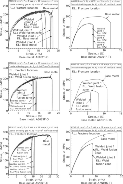
12.7 Tensile test results (stress–strain curves) of base metals and welded joints of A5052P-O, A5083P-O, A5182P-O, A6061P-T6, A6N01S-T5 and A7N01S-T5, showing respective reductions in strengths of welded joints.
The toughness of steels for pipelines, ships, and so on is evaluated by the V-notch Charpy impact test. Fracture pass may occur to apparently show high toughness in the test,40 and then the Charpy test specimens with side notches should be used.41,42
The fatigue strengths of laser and hybrid weld joints are generally higher than those of other fusion welding processes.43 The strengths are higher when the welds have higher hardness and strengths, while they are lower when the welds are weaker than the base metal. It is noted that the fatigue strength of the high tensile strength steel is not so high in comparison with that of the base metal, because the softer zones are formed in the HAZ. The reinforcement may sometimes be removed to improve the fatigue strength by suppressing the stress concentration.
Welding defects such as underfilling, cracking and porosity may remarkably reduce tensile strength and strain (elongation) as well as the fatigue strength by enhancing an actual applied load and by inducing stress concentration.38,44,45 Therefore, to improve the mechanical properties, the prevention of welding defects is essential.
Degradation in chemical properties
In some steels and alloys, stress-corrosion cracking and grain boundary corrosion may take place in the HAZ1. The selection of a material, the use of low heat input welding, reduction or removal of residual stresses, good protection of a weld for preventing oxidation due to an inert shielding gas, etc., are required to improve chemical properties. Grain boundary corrosion due to the precipitation of carbides in the HAZ of austenitic stainless steel is a big problem in other fusion processes such as arc, but may be lessened by low heat input in laser welding. In welding or joining dissimilar metals or alloys, the problem of galvanic corrosion may occur.20 The normal measures such as painting protection and proper applications without water or corrosive environment are required.
12.3 Formation mechanisms and preventive procedures of porosity
12.3.1 X-ray transmission apparatus for observation of bubble and porosity formation
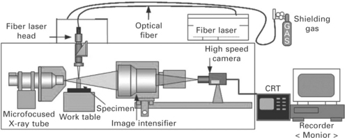
Concerning the formation of porosity during laser welding, brazing and hybrid welding, keyhole behavior, bubble generation situation and melt flows in the molten pool were elucidated by utilizing the microfocused X-ray transmission in-situ observation system. The system is schematically shown in Fig. 12.8.2,24,27,46,47 X-ray transmission observation results are described for spot welding with pulsed YAG laser, bead (melt-run, butt-joint or lap-joint) welding with CW laser, hybrid welding with laser and arc, brazing, welding of Zn-coated steel and cast alloys in the following subsections.
12.3.2 Formation mechanism and preventive procedure of porosity during spot welding with pulsed laser
When the metal or alloy is subjected to spot welding with pulsed YAG laser of rectangular shape, porosity is easily formed in the middle or bottom part of the weld fusion zone in the case of extremely short pulses or deep penetration welds, as illustrated by the welding results of austenitic stainless steel in Fig. 12.9.24,48 Examples of X-ray transmission observation results exhibiting keyhole behavior, and a schematic representation showing formation mechanisms of typical and root porosity are shown in Fig. 12.10.1,24,47 The porosity was observed to form from a collapsed keyhole. The keyhole grows deeper together with some fluctuation. If the laser power is rapidly terminated when the keyhole tip reaches the bottom of a molten pool, the root porosity is formed. When the laser power is terminated by keyhole fluctuation, the porosity is formed near the middle of the spot weld. The gas inside the porosity is mainly air or environmental shielding gas in the case of air or shielding gas atmosphere, respectively. Such porosity can be reduced or prevented by controlling the pulsed laser power.1,17,24,48 Therefore, in the final stage of laser irradiation, a keyhole becomes shallow slowly through the process whereby the melt flows into the bottom tip to bury the keyhole gradually due to the gradual decrease in the laser power. As shown in Fig. 12.11, the prevention of porosity is feasible by a saw-like pulse wave with a reduced power.17,24 The first gradual increase in pulse laser power is used to suppress spattering, and the subsequent three pulses can produce a keyhole from deep to shallow depths depending on the power levels. Bubble generation from a shallow keyhole, leading to porosity formation, should be avoided by the last pulse wave shape.
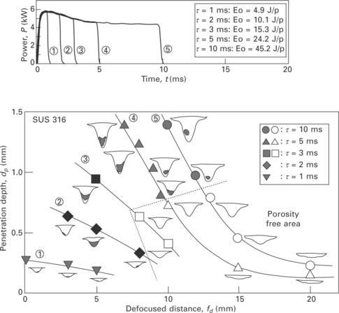
12.9 Effect of defocused distance and pulse width on penetration depths of spot welds with pulsed YAG laser of rectangular shapes, showing formation conditions of porosity.
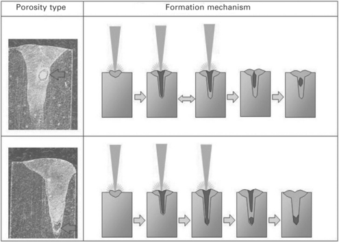
12.10 Examples of typical and root porosity in spot welds of stainless steel, showing schematic illustration of keyhole behavior and porosity formation mechanisms.
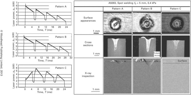
12.11 Examples of saw-like pulse waves, and surface appearances, cross sections and X-ray inspection photos of spot welds produced, showing beneficial effect of controlled shape and gradual increase in pulse laser power on prevention of porosity and suppression of spattering and concave surface, respectively.
12.3.3 Formation mechanisms and preventive procedures of porosity during bead welding with CW laser
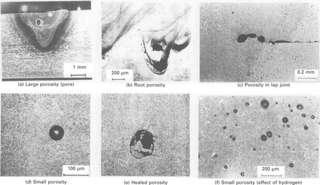
In welding of various metals and alloys with high power CW laser, porosity such as a large pore of more than 1 mm size, root porosity, porosity near the fusion boundaries of the butt or lap joint, small porosity of about 0.1–0.4 mm or less than 0.1 mm size, and healed porosity filled with melt during solidification may be present in the weld fusion zones, as illustrated by the examples of CO2 laser welds of aluminum alloys in Fig. 12.12.2,28,46 Small or large pores are formed from the keyhole tip during welding, as examples of X-ray transmission observation photos during laser welding of A5083 aluminum alloy and Type 304 stainless steel.8,24,27,46 Examples of observation photos during fiber laser welding are shown in Fig. 12.13.8 A lot of bubbles are generated and result in porosity in the case of about 0.6 mm beam diameter, but bubble formation is hardly seen in the case of about 0.13 mm diameter. Very small porosity of less than 0.1 mm in size is formed due to the effect of hydrogen in CO2 laser welding of aluminum alloys with Ar-1%H2 mixture shielding gas. Porosity near the fusion boundaries of the butt or lap joint in aluminum alloys is also formed owing to the effects of a gap between the plates or hydrogen when hydrogen is enriched beneath the surface oxide film or the moisture is high on the surface. Root porosity may occur under defocused minus (−) conditions (of a focal point under the plate surface) or in the case of the existence of interaction between a laser beam and induced plume or plasma in high power CO2, fiber or disk laser welding.
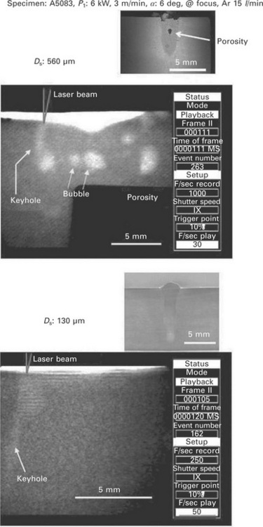
12.13 Cross-sectional weld beads and X-ray transmission in-situ imaging photos observed during welding with fiber laser of 560 and 130 μm in focused beam diameter, showing generation of bubbles leading to formation of porosity.
Based upon the X-ray transmission observation results, bubbles and porosity formation situations are shown together with keyhole behavior and melt flows in Fig. 12.14.1,2,47 At very slow welding speed, an unstable keyhole is easily formed and leads to the formation of bubbles, since a laser beam is irradiated on the wall, which causes the melt downward flows to produce a bubble by closing the bottom keyhole. In this case, the bubbles sometimes disappear from the molten pool surface. Porosity is more easily formed by the generation of bubbles from the tip of the keyhole at slow welding speed. Such large bubbles, resulting in pores or porosity, are generated from evaporation of the keyhole (front) wall. Such porosity is prevented by full-penetration welding. Pulse modulation is sometimes effective. In the case of high power density due to a 0.2 mm small focal beam, bubbles leading to pores or porosity are formed from the middle part of a full-penetration keyhole (at about 5 mm below the focal point). In steels or austenitic stainless steels, porosity is absent due to the ejected plume upwards at high welding speed.
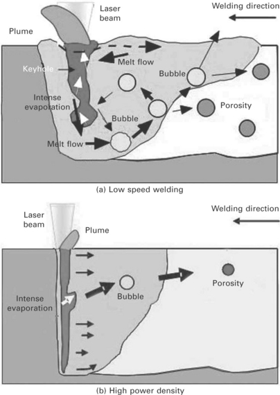
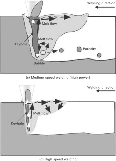
12.14 Schematic illustration of laser welding phenomena under various welding conditions, showing bubbles and porosity formation situations at low speeds and no porosity at high speed, together with plume ejection, keyhole behavior and melt flows in molten pool.
According to the gas analyses of porosity, a large amount of shielding gas, a small amount of hydrogen (H) and sometimes a small amount of nitrogen (N) are detected.1,2,27,45 It is generally considered that the bubbles have the same compositions as a keyhole such as a large number of evaporated vapors and a small number of the other elements composing a shielding gas, and N (nitrogen) or O (oxygen) in air. Vapors and oxygen make oxide films on the porosity inside surface, and the remaining vapors also deposit on the porosity surface as the temperature falls. Consequently, a shielding gas is mainly left in the porosity, and H is contained because it can diffuse into the porosity during and after welding.
The procedures for the suppression or prevention of porosity in laser welding are as follows:1,2
• a heat-conduction type of shallow welding (but it should be noted that another type of porosity may be formed due to the effect of a gap or H in aluminum alloys),
• laser welding with a conical (V-geometry) stable keyhole under the properly defocused conditions,
• full-penetration welding due to a complete-through keyhole (but the laser power density with 0.2 mm focal spot size is too high to induce bubbles in thick plate, and so moderate power density is required),
• vacuum laser welding under the proper conditions,
• welding with a forward inclined laser beam,
• a low welding speed at a high power, which induces melt flows upwards for bubbles to disappear from the molten pool surface, (it was especially observed in laser welding of aluminum alloy),
• a high welding speed, which can suppress or prevent bubble formation,
• pulse-modulated welding for moderate penetration,
• twin laser beam welding (not always effective but the location/arrangement of beams is important to produce a wide and stable keyhole),
• the selection of a proper shielding gas for the material (e.g., N2 gas for austenitic stainless steel and CO2 gas for some steels).
12.3.4 Formation mechanisms and suppression procedures of porosity during welding of materials with great sensitivity to porosity
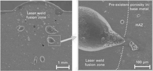
In laser welding of cast alloys, including gases or die-cast or thixomolded alloys, small or large bubbles leading to porosity or pores of various sizes are formed not only from the keyhole tip but also from the origins of very small bubbles of H, N or CO2 gas in the base materials.25,26 An example of porosity in a laser weld of die-cast AZ91 magnesium alloy is shown in Fig. 12.15.25 Such porosity is characterized by the growth of very small holes from the fusion boundaries. Thus it is very difficult to prevent such bubbles and porosity. The contents of H, N or CO2 gas should be reduced. It may be slightly reduced by the use of an intermediate (insert) sheet or a filler wire. In welding of cast alloys, good welds may be formed if the parts with reduced macro-and microsegregation are selected to be welded.
There is a demand for laser butt-joint welding of specimens whose surfaces are prepared by laser cutting. In the case of steels prepared by laser cutting with pure O2 gas, the cut surfaces are covered with oxide films, and consequently porosity may be easily formed probably due to rimming action (FeO + C > Fe + CO) between carbon (C) in the steel and O in the oxide films or a similar phenomenon in the weld molten pool.1,49 To suppress or prevent this porosity, deoxidation elements such as Al, Ti, Mn and Si may be used effectively.49
In laser welding of Zn-coated steel sheets, a proper degree of gap between the sheets is required to prevent porosity.15 Nevertheless, there is a great demand for establishment of laser lap welding of Zn-coated steel sheets without any gap. The examples of surfaces, cross sections and X-ray inspection results of laser welds made at 1–5 mm/s under the conditions of pulse-modulation are shown in Fig. 12.16.14 In the case of a 0 mm gap, worm-like porosity is formed from the fusion boundaries of the lap joint at low welding speed. On the other hand, at high welding speed, underfilled weld beads are formed by spattering of melts. Nevertheless, under the conditions of proper pulse modulation and adequate welding speeds, porosity and underfilling are reduced or suppressed by the procedures that laser power decreases before the occurrence of spattering and low heat input due to pulsation of laser power can prevent Zn vapors from invading into the molten pool by suppressing the amount of Zn evaporation.
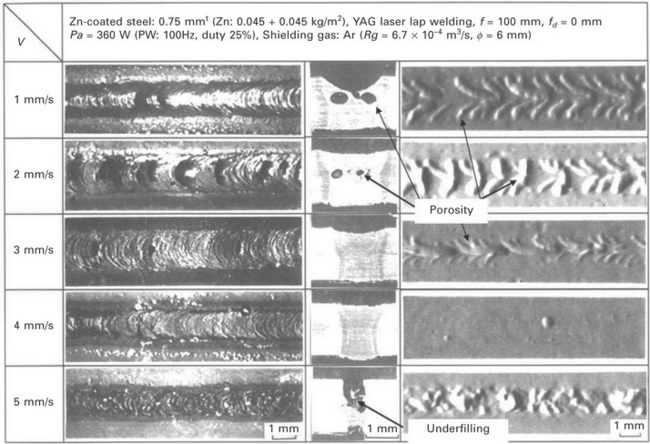
12.16 Surface appearance, cross sections and X-ray inspection results of laser welds produced at 1–5 mm/s under pulse-modulation conditions, showing effect of welding speed on formation of porosity and underfilling.
Laser welding phenomena are schematically shown in Fig. 12.17.14 In the case of a large heat input, the molten pool is so big that spattering is suppressed but porosity is formed. In the case of normal focal beam spot (of about 0.6 mm diameter), the smaller the molten pool, the more severely the spattering occurs. Such spattering leading to poor weld beads can be prevented by setting the gap to about 0.05–0.3 mm for lapped sheets. Spattering should be reduced with an increase in the thickness of the upper sheet. Porosity should also be reduced with an increase in the welding speed in thick Zn-coated plates.
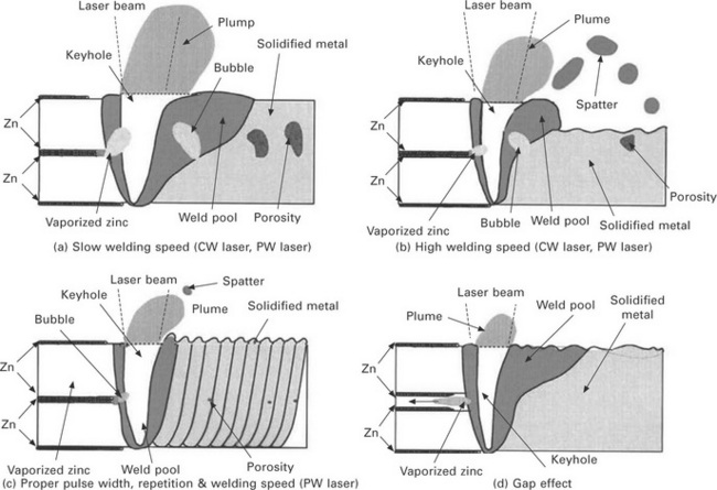
12.17 Phenomena during laser welding of Zn-coated steel lap sheets with or without gap, showing porosity (a), underfilled bead due to spattering (b), reduced porosity due to pulse modulated laser (c), and sound weld bead due to gap effect (d).
In laser lap welding of Zn-coated steel sheets, the procedures recommended for the production of good weld beads are as follows:1,14,15,50–53
• control of the gap between sheets at about 0.05 to 0.3 mm depending on the Zn-coating layer thickness,
• device or modification of lap joint geometry (which can produce a proper gap),
• removal of Zn-coated layer at the lap joint part,
It is probably considered that backward inclination welding and hybrid welding can produce a gap naturally during welding by inducing deformation of the upper sheet. Besides, laser butt-joint welding of Zn-coated steel sheets can produce welds without defects, since the Zn layer on the surface has little effect on the welding results.
12.4 Formation mechanisms and preventive procedures of hot cracking: solidification cracking and liquation cracking
Hot cracking generally occurs along grain boundaries in the welds of aluminum alloys, Ni-based alloys, etc., when the liquid films are formed along grain boundaries near the nominal solidus temperature, and tensile strains higher than the minimum ductility for cracking initiation are applied at a higher rate than the critical strain rate for cracking occurrence, as illustrated by the example of solidification cracking shown in Fig. 12.18.2,36 The cracking takes place in the weld fusion zone and in the HAZ near the fusion boundary. The hot cracking in the weld fusion zone and the HAZ is called ‘solidification cracking’ and ‘liquation cracking’, respectively.1,2 In Invar, hot cracking called ‘ductility-dip cracking’, which has no relationship with liquid films, may occur in the previous weld metal heated as HAZ by the subsequent welding process.1
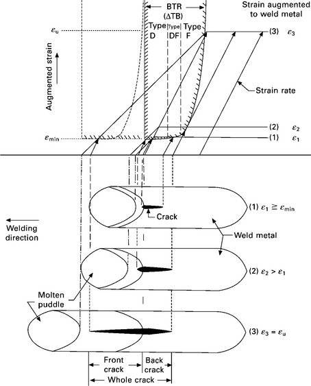
12.18 Strain levels applied at constant strain rate for ductility curve of BTR (brittleness temperature range) during weld solidification, showing crack initiation above the minimum strain and solidification length according to applied strain level.
In laser welding, cracking is most likely to occur as solidification cracking along grain boundaries due to the rapid growth of cellular dendrite tips and the consequent formation of low solidification temperature liquid films in the central part of the spot made with a pulsed laser. In spot welding, the tailing laser power is preferable if the area of mushy zone can be narrowed owing to the suppression of the rapid growth of the dendrite tips, as shown in Fig. 12.19.19
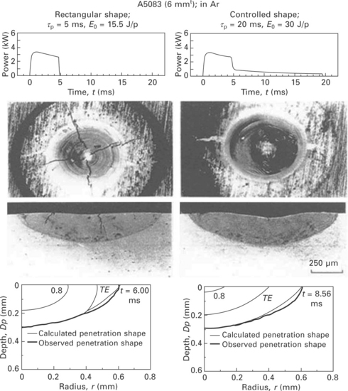
12.19 Surface appearance and cross sections of spot welds made with pulsed lasers of rectangular shape and controlled shape, and calculation result of solid–liquid ratio at initiation of solidification of spot center, showing cracking due to wide solid–liquid zone by rapid solidification and reduced cracking due to narrowed solid–liquid zone with additional level of tailing laser power.
Solidification cracking may take place in deep, partial-penetration weld beads made in thick steel plates with CW high power laser or by hybrid welding with high laser power and high arc current.17,22 The causes may be attributed to the formation of wide retained molten areas due to melt flows near the bottom part of the laser or hybrid weld beads. The optimization of weld penetration depth or bead geometry or the selection of a filler wire is recommended.22 In a thick plate of high tensile strength steel, cracking occurs in the weld bead made in a shielding gas (at 1 atm), but is prevented in the weld produced at 16 kW, 1.2 m/min and 0.1 kPa, as shown in Fig. 12.20.17 Under low vacuum, a sound full-penetration weld bead can be produced in 23 mm thick plate by one-pass welding.17
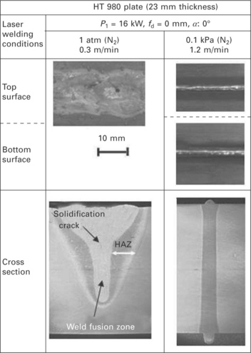
12.20 Partial-penetration and full-penetration welds in HT 980 with disk laser at 1 atm and 0.1 kPa, showing crack and no crack in the weld fusion zone, respectively.
The conditions for cracking in laser-welded A7N01 alloy are shown as functions of plate thickness and welding speed in Fig. 12.21.2,3 It is considered in aluminum alloys that solidification cracking is more likely to occur in a thicker plate at a higher welding speed.
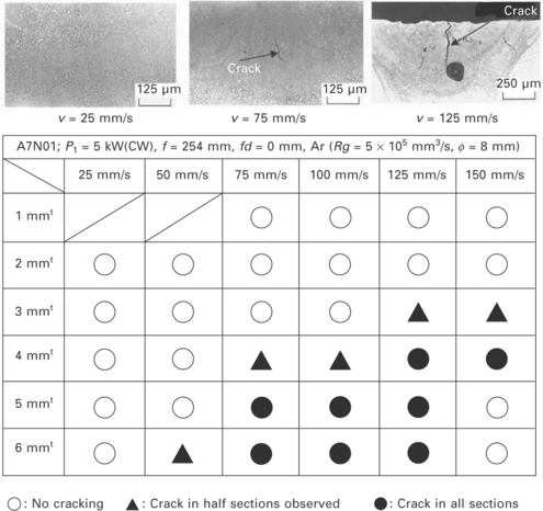
12.21 Conditions of cracking formation in laser weld fusion zones of A7N01 alloy, showing effects of welding speed and plate thickness on cracking susceptibility.
Observation of cracking surfaces is important in understanding the occurrence mechanism of solidification cracking. Generally, long cellular dendrites are observed. If the surface is characterized by clear dendrites, cracking should occur at high temperatures near the liquidus. If both cellular-dendritic and flat features are observed, it is supposed that the strain should be rapidly applied to the boundary, and consequently cracking occurs at a dendritic area of higher temperature and propagates along the grain boundary to a lower temperature region. On the other hand, in the HAZ of Ni-based alloys, etc., as the heating speed is fast during laser welding, compositional liquation should occur along the grain boundary between the base metal and an inclusion, which results in a higher possibility of liquation cracking.
The hot cracking susceptibility of aluminum alloys is summarized as a function of alloying content in Fig. 12.22.2,54–61 In each alloy system, cracking susceptibility increases with an increase in the alloying content to a certain level, and then the susceptibility decreases with the increase in the eutectic content. In normal welding, therefore, cracking prevention is tried by controlling compositions in the molten pool using a filler wire with a high content of Si or Mg.2,32,54,62
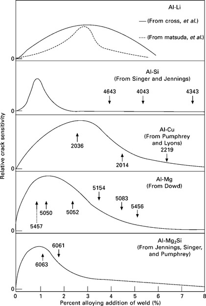
12.22 Effects of alloying element and content on hot cracking susceptibility of welds in aluminum alloys.
From the above results, the relationship between cracking susceptibility, laser welding process and the plate thickness is schematically summarized in Fig. 12.23.1,2,36 Cracking susceptibility is the highest in spot welding with a pulsed laser, and is the lowest with CW laser welding of thin sheet (of about 1–3 mm thickness) under the proper welding conditions. However, it is noted that a rotational crack may occur when the full-penetration welding of thin sheets starts near the end.
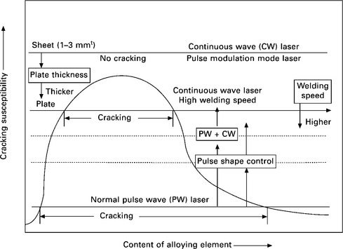
12.23 Schematic representation of effects of various factors on solidification cracking susceptibility of laser welds.
In order to reduce or prevent weld hot cracking, it is necessary to take measures from the viewpoints of both material or metallurgical and mechanical factors. In laser welding, therefore, the following measures are considered:
• proper selection of the base metal, its thickness and weld fusion zone geometry,
• proper control of molten pool compositions by using a filler wire, and
• adoption of proper welding conditions for narrowing a mushy zone as well as suppression of rapid solidification and rapid tensile strain during solidification.
12.5 References
[1] Katayama, S., Formation mechanisms and preventive procedures of laser welding defects. 2004 LMP Symposium on High Quality and New Trend of Laser Welding. 2005. [Laser Materials Processing (LMP) Research Committee of Japan Welding Engineering Society (JWES), January, 8-1–8-15 (in Japanese)].
[2] Katayama, S., Matsunawa, A. Laser weldability of aluminum alloys. Proc. 43rd Laser Materials Processing Conference, Japan Laser Processing Society (JLPS). 1998; 43:33–52. [(in Japanese)].
[3] Suzuki, H. Recent Welding Engineering; 142. Corona Publishing, Tokyo, 1971. [206, (in Japanese)].
[4] Welding Society Edition, Japan. Welding and Joining Handbook. Tokyo: Maruzen, 1990; 13–41. [(in Japanese)].
[5] Gabzdyl, J., Johnson, A., Williams, S., Price, D. Laser weld distortion control by cryogenic cooling. Osaka. Proc. SPIE (LAMP 2002), JLPS. 2003; 4831:269–274.
[6] Mataumoto, T., Yoshida, M., Welding conditions and mechanical properties of laser welded butt joints of aluminum alloy Japan Laser Processing Society (JLPS),. Proc. 43rd Laser Materials Processing Conference;. 1998; 43:71–82. [(in Japanese)].
[7] Kawahito, Y., Mizutani, M., Katayama, S. High quality welding of stainless steel with 10 kW high power fibre laser. Science and Technology of Welding and Joining. 2009; 14(4):288–294.
[8] Nagayama, H., Mizutani, M., Kawahito, Y., Katayama, S., Laser welding phenomena of aluminum alloy with high-power fiber laser Osaka. Proc. 10th International Conference on Joints in Aluminium (INALCO 2007). 2007:137–142.
[9] Katayama, S., Uchiumi, S., Mizutani, M., Wang, J., Fujii, K. Penetration and porosity prevention in YAG laser-MIG arc hybrid welding of aluminum alloy. J Light Metal Welding & Construction. 2006; 44(3):99–109. [(in Japanese)].
[10] Onishi, T. H., Mizutani, M., Kawahito, Y., Katayama, S. High-power fiber laser butt welding of thick high-strength steel plate using sensing system with hot wire. Proc. 28th International Congress on Applications of Lasers & Electro-Optics (ICALEO 2009), LIA. 2009; 102:773–779.
[11] Katayama, S., Onishi, T. H., Mizutani, M., Kawahito, Y., High-power laser butt welding of high-strength steel thick plate. IIW Annual Meeting 2010, Commission IV. 2010:1–7. [Turkey, IV-1031-10].
[12] Wahba, M., Mizutani, M., Kawahito, Y., Katayama, S. Keyhole stability in disc laser welding of AZ31B and AZ61A magnesium alloys and weld metal properties. Science and Technology of Welding and Joining. 2010; 15(7):559–566.
[13] Wang, J., Nishimura, H., Katayama, S., Mizutani, M. Penetration and porosity prevention in YAG laser-MIG arc hybrid welding of aluminum alloy. J Light Metal Welding & Construction. 2006; 44(3):99–109. [(in Japanese)].
[14] Katayama, S., Wu, Y., Matsunawa, A., Laser weldability of Zn-coated steels. Congress Proc. of ICALEO 2001 (Laser Materials Processing Conference). 2001. [LIA, Jacksonville, Welding-P520 (CD). ].
[15] Akhter, R., Steen, W. M., Watokins, K. J. Laser welding of Zn-coated steel sheets. J Laser Applications. 1991; 3(2):9–20.
[16] Katayama, S., Mizutani, M., Ikeda, H., Nishizawa, K., Matsunawa, A., Effect of pulse shaping on defect reduction in pulsed laser welding. Proc. ICALEO ’92;. 1992; 75:547–556. [LIA, Orlando, FL,].
[17] Katayama, S., Abe, Y., Ido, R. H., Mizutani, M., Kawahito, Y., Deep penetration welding with high power disk lasers in low vacuum. Congress Proc. 30th ICALEO;. 2011; 104:669–678. [LIA, Orlando, FL].
[18] Katayama, S., Lundin, C. Laser weldability of aluminum alloy 2090’, J. Light Metal Welding & Construction. 1991; 29(9):403–415. [(in Japanese)].
[19] Katayama, S., Mizutani, M., Matsunawa, A. Modelling of melting and solidification behaviour during laser spot welding. Science and Technology of Welding and Joining. 1997; 2(1):1–9.
[20] Katayama, S. Laser welding of dissimilar materials. The Review of Laser Engineering. 2010; 38(8):594–602. [(in Japanese)].
[21] Stout, R. D. Weldability of Steels, 4th edn. New York: Welding Research Council; 1987.
[22] Katayama, S. Laser welding. Ferrum (Bulletin of The Iron and Steel Institute of Japan). 2012; 17(1):18–29. [(in Japanese)].
[23] Vondrous, P., Katayama, S., Dunovsky, J., Specifics of laser welding of ductile iron, Cr-Mo steel and their dissimilar butt joints. Proc. 74th Laser Materials Processing Conference;. 2010; 74:89–98. [JLPS].
[24] Katayama, S., Seto, N., Mizutani, M., Matsunawa, A., X-ray transmission in-situ observation of keyhole during laser spot welding and pulse-shaping for prevention of porosity. Congress Proc. of ICALEO. 2001; 2001:. [LIA, San Jose, 74, Session C: Welding-804 (CD)].
[25] Morita, S., Katayama, S., Matsunawa, A., Hino, M., Laser weldability of magnesium alloys. High Energy Density Research Committee of Japan Welding Society (JWS). 2001. [(2001), EBW-495-01].
[26] Wahba, M., Mizutani, M., Kawahito, Y., Katayama, S. Laser welding of die-cast AZ91D magnesium alloy. Materials and Design. 2011; 33:569–576.
[27] Katayama, S., Seto, N., Kim, J. D., Matsunawa, A., Formation mechanism and suppression procedures of porosity in high power laser welding aluminum alloys. Proc. of ICALEO ’ 1998; 98:24–33. [LIA, Orlando, FL, 85, Sec. C].
[28] Katayama, S., Lundin, C. Laser weldability of aluminum alloy 5456’, J. Light Metal Welding & Construction. 1991; 29(7):295–307. [(in Japanese)].
[29] Kawahito, Y., Katayama, S. In-process monitoring and adaptive control for stable production of sound welds in laser micro-spot lap welding of aluminum alloy. J Laser Applications. 2005; 17(1):30–37.
[30] Katayama, S., Lundin, C. Laser weldability of various commercially available aluminum alloys. J Light Metal Welding & Construction. 1991; 29(8):349–360. [(in Japanese)].
[31] Todate, A., Ueno, Y., Katsuki, M., Katayama, S., Matsunawa, A. Porosity formation in carbon steels welded with YAG laser in CO2 shielding gas. Pre-Prints of the National Meeting of JWS. 2001; 69:46–47.
[32] Katayama, S., Kim, J. D., Matsunawa, A., Cracking susceptibility of laser welds in aluminum alloys, and effect of nitrogen shielding gas on crackingSymposium on ‘Present state and future trend of laser welding of aluminium alloys. Tokyo: Japan Light Metal Welding and Construction Association, 1999. [66–77].
[33] Katayama, S., Kojima, K., Matsunawa, A. CO2 laser weldability of aluminum alloys (Report 3) – Metallurgical characteristics of laser welds. J Light Metal Welding & Construction. 1999; 37(2):47–58. [(in Japanese)].
[34] Vollertsen, F., Laser joining of aluminium alloys – state of the art. IIW Annual Meeting. 2011; 2011:. [Commission IV, Chennai, IV-1057-11. ].
[35] Katayama, S. Solidification phenomena of weld metals (2) – Solidification theory, solute redistribution and microsegregation. J Light Metal Welding & Construction. 2000; 38(4):168–180. [(in Japanese)].
[36] Katayama, S. Solidification phenomena of weld metals (3) – Mechanism and susceptibility of solidification cracking. J Light Metal Welding & Construction. 2000; 38(9):417–427. [(in Japanese)].
[37] Katayama, S., Ogawa, K. Laser weldability and aging characteristics of welds – laser weldability of commercially available A7N01 alloy (1). J Light Metal Welding & Construction. 2010; 48(12):463–474. [(in Japanese)].
[38] Katayama, S., Kojima, K., Kuroda, S., Matsunawa, A. CO2 laser weldability of aluminum alloys (Report 4) – Effect of welding defects on mechanical properties, deformation and fracture of laser welds. J Light Metal Welding & Construction. 1999; 37(3):95–103. [(in Japanese)].
[39] Yasuyama, M., Uchihara, M., Fukui, K. Proc. 64th Laser Materials Processing Conference, Japan Laser Processing Society (JLPS);. 2005; 64:52–59. [(in Japanese)].
[40] Arata, Y., Matsuda, F., Shibata, Y., Hozomi, S., Ono, Y., Fujihira, S. Mechanical properties on electron beam welds of constructional high tension steel (Report III). Trans JWRI. 1975; 4(2):181–187.
[41] Minami, F. Evaluation of fracture toughness and structural integrity of laser welds of structural steels. J Japan Laser Processing Society. 2011; 18(2):94–102. [(in Japanese)].
[42] Inose, K. Functional assessments of laser welded joint’, J. Japan Laser Processing Society. 2011; 18(2):63–68. [(in Japanese)].
[43] Inose, K., Oowaki, K., Kurata, Y., Application of laser welding to bridges. LMP Symposium 2011 on Latest Trend of Laser Processing Technology in Japan and Europe, Laser Materials Processing (LMP) Research Committee of Japan Welding Engineering Society (JWES). 2011. [January 117–125 (in Japanese)].
[44] Katayama, S., Yamaguchi, Y., Mizutani, M., Matsunawa, A., Evaluation of mechanical properties of laser-welded aluminum alloy. Proc. ICALEO’97. 1997. [LIA, San Diego, CA, 83, Part 2, Section G, 93–102].
[45] Mizutani, M., Yamaguchi, Y., Katayama, S. Fatigue properties of laser-welded aluminum alloy. J Light Metal Welding & Construction. 2008; 46(2):56–64. [(in Japanese)].
[46] Katayama, S., Seto, N., Kim, J. D., Matsunawa, A., Formation mechanism and reduction method of porosity in laser welding of stainless steel. Proc. ICALEO ’97. 1997. [LIA, San Diego, CA, 83, Part 2, Section G 83–92].
[47] Katayama, S., Kawahito, Y. Visualization of welding phenomena with high speed video camera and X-ray transmission real-time observation system. J High Temperature Society. 2007; 33(3):118–127. [(in Japanese)].
[48] Katayama, S., Kohsaka, S., Mizutani, M., Nishizawa, K., Matsunawa, A., Pulse shape optimization for defect prevention in pulsed laser welding of stainless steels. Proc. of ICALEO ’93; 77, 1991. [LIA, Orlando, FL, 487–497].
[49] Ono, K., Adachi, H., Katada, K., Miyoshi, M., Miyamoto, I., Inoue, T. Laser welding phenomena of steel plate with oxide film – Effect of oxide film in high power CO2 laser welding (Report I). Quaternary J. of Japan Welding Society. 2002; 20(2):213–219. [(in Japanese)].
[50] Graham, M. P., Hirak, D. M., Kerr, H. W., Weckman, D. C. Nd:YAG laser welding of coated sheet steel. Proc. of ICALEO ’93, LIA. 1993; 77:651–660.
[51] Gu, H. A new method of laser lap welding of zinc-coated steel sheet. Section C. Proc of ICALEO, LIA, Dearborn. 2000; 89:1–6.
[52] Ono, M., Shinbo, Y., Yoshitake, A., Ohmura, M., Welding properties of thin steel sheets by laser-arc hybrid welding – Laser focused arc welding. Proc. SPIE (LAMP 2002), JLPS. 2003 4831 Osaka, 369–374
[53] Dasgupta, A., Mazumder, J., Bembenk, M. Alloying based laser welding of galvanized steel. Section A. Proc. of ICALEO 2000, LIA, Dearborn. 2000; 91:38–45.
[54] Martukanitz, R. P. The metallurgy of aluminum welding, 1988. [Product Manufacturing Technology Division Report Number 52–88–06 Alcoa Technical Center, PA. ].
[55] Singer, A. R. E., Jennings, P. H. Hot-shortness of the aluminum–silicon alloys of commercial purity. J. Inst. Metals. 1947; 74:197–212.
[56] Dowd, J. D. Welding cracking of aluminum alloys. Weld. J.. 1952; 31:10448s–10456s.
[57] Cross, D. E., Olson, D. L., Edowards, G. R., Capes, J. F., Weldability of aluminum–lithium alloysSanders T. H., Starke E. A., eds. Aluminum-Lithium Alloy II. 1984:675–682. [TMS/AIME, Warrendale, PA,].
[58] Matsuda, F., Nakata, K., Tsukamoto, K., Effect of Li on solidification cracking susceptibility of aluminum alloy. Preprints of the National Meeting of J. W. S. 1987. [41, October, 308–309 (in Japanese). ].
[59] Jennings, P. H., Singer, A. R. E., Pumphrey, W. I. Hot shortness of some high-purity alloys in the systems aluminum–copper–silicon and aluminum–magnesium– silicon. J. Inst. Metals. 1948; 74:15–52.
[60] Pumphrey, W. I., Moore, D. C. A consideration of the nature of brittleness at temperature below the solidus in castings and welds in aluminum alloys. J. Inst. Metals. 1948; 75:257–267.
[61] Pumphrey, W. I., Moore, D. C. Cracking during and after solidification of some Al–Cu–Mg alloys of high purity. J. Inst. Metals. 1948; 74:425–438.
[62] Binroth, C. A., Zuo, T. C., Sepold, G., CO2-laser welding with filler material of high strength aluminum alloys. Proc. of Power Beam Technology. 1990:119–127. [September,].

