Developments in beam scanning (remote) technologies and smart beam processing
Abstract:
This chapter describes the state of the art as well as the future trends of fast laser beam deflection and shaping for welding applications. The key principles of fast laser beam manipulation like galvanometer-driven and conventionally-driven mirrors are introduced. The beam movement over the workpiece as the first purpose and beam shaping as the second purpose are discussed in detail and explained by means of welding examples. Finally, an outlook for future trends and forthcoming requirements for the beam scanning equipment is given.
15.1 Introduction
A relative motion between the focused laser beam and the workpiece is needed in order to generate a welding seam. Usually, three axes are sufficient for a 2D and rotation-symmetric application like laser beam welding of a flat panel or drive shaft. Five axes are only needed in the case of three-dimensional welding. These axes can be designed completely as workpiece axes, split into workpiece and tool axes, or designed completely as tool axes. For conventional machines, the most dynamic set-up is achieved by a so-called split axes concept. However, maximum welding speed and acceleration, which are important for positioning motions, are limited by the mass inertia of the mechanical axis. A more elegant way to provide fast motion for welding and positioning is only to move the laser beam in lateral direction x and y by one or two deflection mirrors and to move the focusing optics in one direction where required. The focusing optics can be arranged in front of the bending mirrors or behind them (in the direction of beam propagation) (Kögel, 2011; Lütke, 2011).
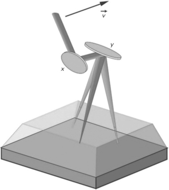
The most common way to move the laser in the lateral direction is to utilize galvanometer-driven mirrors. It is the fastest method whereas the working field is limited to a size of typically 300 mm × 300 mm and the transmitted laser power is limited to 8 kW (Fig. 15.1). An alternative solution consists of using conventional direct rotary drives which has the advantage to be able to move bigger masses, e.g. larger mirrors that are providing a larger working envelope. There are two options available for these so-called large field scanners: usage of two mirrors (one for each direction) or usage of one gimbal mounted mirror (SEF, 2011).
In the case of beam shaping, where only small amplitudes are needed, an alternative way to move the laser beam is conducted by means of rotating mirrors or rotating prisms (Meier, 2006; Harris, 2001). In order to focus the laser beam, an objective is necessary which can be arranged either in front of the scanning unit or behind it.
CO2 lasers are established as laser sources for remote welding processes since these lasers are available on the market with single mode beam quality (Bachmann, 2007). Nowadays, solid-state lasers, e.g. fiber lasers and disc lasers are representing an alternative laser source (Hammer and Brockmann, 2006). Since the beam parameter product of single mode CO2 laser and multi-mode fiber or disc lasers are in the same range (2–4 mm mmrad) mirror sizes, focal length, and focal size of the laser beam are similar. The main difference concerns the coating of the mirrors as well as the material of the focusing optics. Another challenge is the required surface roughness of the mirrors which must be better than a tenth of the wavelength. That means in the case of a fiber or disc laser, a surface roughness of 0.1 mm is needed.
15.2 Beam movement over the workpiece
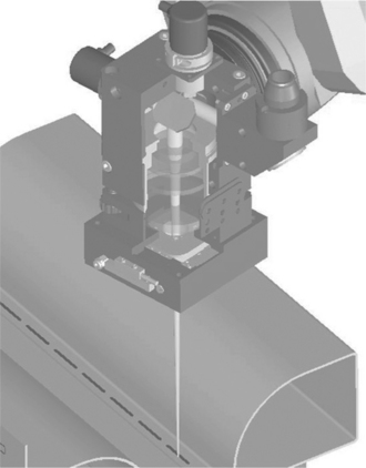
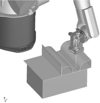
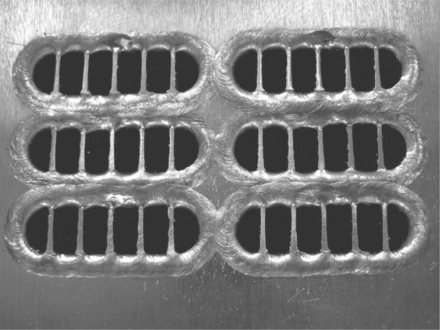
A typical example of a scanning head is shown in Fig. 15.2. The typical welding speed of less than 20 m/min can be achieved easily by this experimental set-up. The biggest advantage compared with conventional welding systems, besides the more cost-effective system set-up, consists of the fast positioning speed that can be provided between the single welding seams (Munzert, 2009). The disadvantage is the limited working field of about 300 mm × 300 mm. This drawback can be overcome by a combination with a robotic movement (Fig. 15.3). Figure 15.4 shows a typical example of welding of an automotive heat exchanger made of stainless steel by means of a CO2 laser.
The scanning head is hooked up to the arm of the robot which provides a smooth path movement over the whole of the workpiece to be welded, whereas the scanning head is conducting the motion needed for the welding process as well as for the positioning within a superposition. Due to the fact that the high speed and the precision of scanning optics are combined with the flexibility of a robot, this welding technique is widespread among the automotive industry to join sheet metal. In particular it has become a standard production technology within the body-in-white manufacturing (Hopf, 2010). Typical examples of body-in-white applications are remote welding of doors, inner side walls, and rear center sections. The biggest advantage of remote welding by using scanning technology in combination with robots is to raise productivity by up to 100% through reduction of non-productive positioning times.
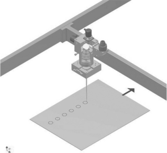
Another option is to combine the scanning head with a Cartesian system, in particular when the welding seams are within one level (2D) and therefore an axes extension is needed, mainly in two, or better only in one, direction (Fig. 15.5) (Bartels, 2011).
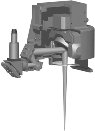
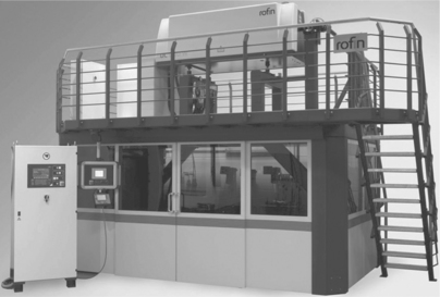
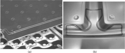
Another alternative is a large-scale remote welding system (Fig. 15.6). The working field of about 2,000 mm × 2,000 mm is achieved by means of focal length up to 2,000 mm which requires a raw beam diameter of about 100 mm. Such a system is mainly used as a stand-alone system (Fig. 15.7) (SEF, 2011). Figure 15.8 shows typical welding seams, whereas the seam on a 2D-part in Fig. 15.8(a) was generated by means of superposition of scanning head with linear axes and the seam on a 3D part in Fig. 15.8(b) was generated by means of a large-scale remote welding system.
15.3 Beam shaping
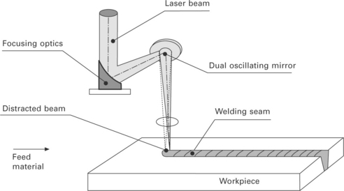
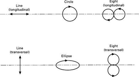
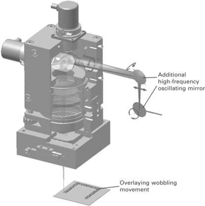
A different goal of using fast beam scanning methods is to provide beam shaping. Beam shaping in the case of laser welding is necessary to provide a fast keyhole movement which enables a variable shape of the welding seam by affecting the metallurgy, the energy input per unit length, and the solidification behavior. In order to achieve these effects, oscillations of the laser beam in the range of a maximum of 1 mm on the workpiece are needed. The method of choice is to use two galvanometer-driven mirrors which will allow a superposition with the feed motion (Fig. 15.9). Due to the fact that both mirrors can be operated independently, circular, ellipsoidal, and linear oscillations along and across the feed direction are possible (Fig. 15.10) (Mahrle and Beyer, 2007).
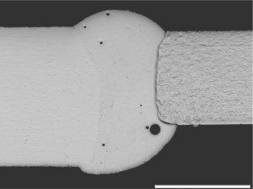
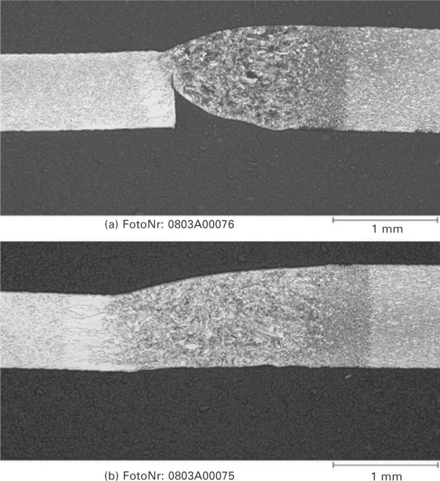
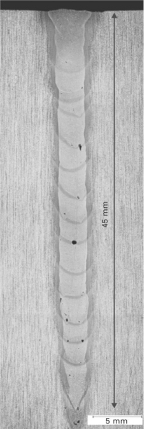
State-of-the-art scanning heads are approaching maximum frequencies of about 4 kHz (Krätzsch et al., 2011), which is sufficient for most welding processes. The beam shaping can be utilized to improve the weldability of dissimilar metallic materials like copper and aluminum (Fig. 15.11), to enhance the joining capability for butt welding of thin material (Fig. 15.12) as well as to enable narrow-gap welding (Fig. 15.13).
15.4 Future trends
Remote laser welding is already an established manufacturing process. Momentum to further develop this welding technique will come from the requirements of the joining process itself and from the availability of solidstate lasers in single mode beam quality (Havrilla and Brockmann, 2009, 2010; Gapontsev, 2009). The latter will lead to smaller laser spot sizes and therewith to narrower welding joints, if the same optical set-up is used. By maintaining the same focus size, the usage of fraction limited lasers will allow the size of the optics and deflections mirrors to be reduced, which will enhance the dynamics (e.g. positioning speed) of the whole system. Thus, diffraction limited solid-state lasers enable narrower welding joints, reduction of laser power, and faster positioning between separate joints. One of the future challenges that comes from the process is the requirement to join dissimilar materials like aluminum to copper. Therefore, scanning mirrors as shaping systems will be combined with deflection systems for beam movement over the workpiece. One option is to utilize only one deflection system, whereas the scanning mirrors provide the oscillation motion, which is necessary for beam shaping and the deflection of the laser beam within a larger angle range for guiding the beam on the workpiece. The other option would be to combine two scanning heads as illustrated in Fig. 15.14. Another trend will result from more dynamic scanning mirrors. This can be achieved by using lightweight carrier material for the mirrors like SiC or Be and by using resonance scanners.
15.5 References
Bachmann, F. High Power Laser Sources for Industry and their Applications. Proceedings of SPIE. 2007; 6735:67350T.
Bartels, F. Beitrag zur Erhöhung der mittleren Bearbeitungsgeschwindigkeit beim Laserstrahlschneiden komplexer Bauteilgeometrien. Stuttgart: Fraunhofer Verlag; 2011.
Gapontsev, Recent Progress in Scaling High Power Fibre Lasers at IPG PHOTONICS. 22nd Annual Solid State and Diode Laser Technology Review, Newton, MA, June 29-July. 2009; 2:.
Hammer, T., Brockmann, R. Scannerschweißen mit dem Scheibenlaser – Auf dem Weg zur Serienanwendung. LaserTechnikJournal. 2006; 3(3):36–38.
Harris, J., The Cutting of Thick Steel Plate using a Spinning Nd:YAG Laser Beam. 20th ICALEO. 2001:221–228.
Havrilla, D., Brockmann, R. Third Generation of Disk Lasers. LaserTechnikJournal. 2009; 6(3):26–31.
Havrilla, D., Brockmann, R. Latest Advances in High Power Disk Lasers, 2010. CA: SPIE. San Francisco; 2010. [C1–C11].
Hopf, B., Remote Laser Welding: Future Developments and Quality Assurance. AKL'10 International Laser Technology Congress, Proceedings. 2010:111.
Kögel, G. High Power Scanning. Journal EuroLaser. 2011; 4:28–31.
Krätzsch, M., Standfuß, J., Klotzbach, A., Kaspar, J., Brenner, B., Beyer, E. Laser Beam Welding with High-Frequency Beam Oscillation: Welding of Dissimilar Materials with Brillant Fiber Laser, Lasers in Manufacturing 2011. Proceedings. 142–149, 2011.
Lütke, M. Entwicklung des Remote-Laserschneidens metallischer Werkstoffe. Dissertation: TU Dresden; 2011.
Mahrle, A., Beyer, E. Control of energy deposition during laser beam welding by oscillation techniques, Lasers in manufacturing 2007. Proceedings, pp.. 97–104, 2007.
Meier, O. Hochfrequentes Strahlpendeln zur Erhöhung der Prozessstabilität beim Laserstrahlschweißen. Abschlussbericht AIF-Vorhaben. 13660N, 2006.
Munzert, U. Bahnplanungsalgorithmen für das robotergesteuerte Remote-Laserstrahlschweißen, 2009. [Technische Univerität München].
SEF. Die Laser Remote-Technik. SEF Roboter GmbH, Scharnebeck: Grundlagen-Lieferprogramm; 2011.

