Developments in CO2 laser welding
Abstract:
This chapter describes carbon dioxide laser (CO2 laser) welding. Some types of CO2 lasers and special features of CO2 lasers are introduced in the first sections. Laser welding phenomena, which include the interaction of the laser beam with materials and gases, keyhole behaviour, formation mechanism and prevention of weld defects, are also described. Finally, some practical applications of CO2 laser welding are introduced.
2.1 Introduction
C.K.N. Patel, working for Bell Laboratories, invented the CO2 laser in 1964. He succeeded in producing 1 mW pure CO2 lasers. The power and efficiency was much improved by addition of nitrogen and helium in the medium gas. The first commercial 100 W CO2 laser was put on the market in 1966 by Coherent. Since then, CO2 lasers have undergone continuous development and at the end of twentieth century, high power lasers operating at up to 50 kW were used for materials processing.
The wavelength of the CO2 laser beam is normally 10.6 μm and it is about 10 times longer than that of solid-state laser beams. The long wavelength significantly affects the interaction of the laser beam with materials, shielding gases and plasmas and determines the characteristics of laser welding behaviour and laser systems. In this chapter, the principle and types of CO2 lasers, characteristics of CO2 laser beam, CO2 laser–materials interaction, CO2 laser welding behaviour and practical applications of CO2 laser welding are described.
2.2 Laser principles and types of lasers
A mixture of carbon dioxide, nitrogen, and helium is used as a laser medium in CO2 lasers. It is excited by DC or high frequency AC (generally RF) discharge to generate the laser beam with normally 10.6 μm wavelength.
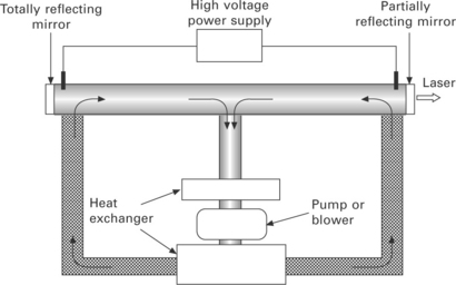
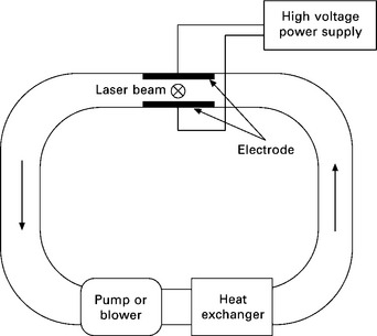
There are some types of CO2 lasers that are classified mainly by a heat removal method and flow direction of the laser medium. The first type is slow flow lasers. The laser gas slowly flows during discharge and the gas is cooled mainly through the cavity wall. A high-quality stable laser beam can be produced. However, the laser output power is normally small, because a very long cavity is required to achieve high power. Fast axis flow lasers increase the gas flow rate by circulating the gas with pumps or blower systems. The gas is cooled by heat exchangers set in the gas circulation path as shown in Fig. 2.1. The gas flow and laser beam have a common axis. High power lasers up to 20 kW with high beam quality are available in this type of laser. In transverse flow lasers, the laser beam axis is orthogonal to the discharge and gas flow as shown in Fig. 2.2. The laser gas is also cooled by circulation of the gas flow. This type of laser can achieve the highest laser power, although the beam quality is lower than the fast axis flow laser. Industrial lasers up to 50 kW are available. Slab lasers are classified as slow flow lasers. The laser medium is excited in a narrow space between two wide water-cooled electrodes as shown in Fig. 2.3. The wide discharge area and efficient heat removal through the wide electrodes enable high power and high beam quality laser beam to be generated. High power lasers up to 8 kW with M2 = 1.05 are available.
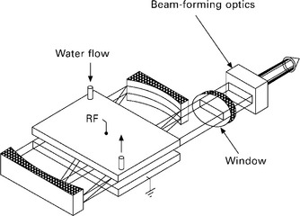
2.3 RF excited slab laser (from Davis, 2001).
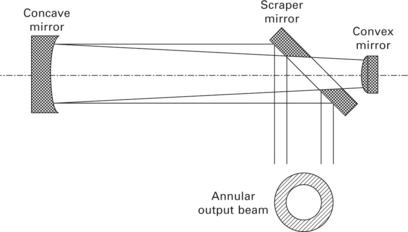
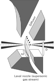
Relatively low power lasers up to 6 kW have stable resonators, where the output mirror is partially transparent to 10.6 μm infrared radiation. On the other hand, high power lasers have unstable resonators as shown in Fig. 2.4 to avoid distortion and damage to the mirror. The unstable resonator consists of concave and convex mirrors with a scraper mirror. The scraper mirror is located in front of the convex mirror and reflects the outer annulus of the beam from the cavity to produce the annular output beam. Zinc selenide (ZnSe) is normally used as a material of output windows. For high power CO2 lasers of more than 10 kW, an aerodynamic window is used to avoid thermal distortion and damage to the ZnSe window. As shown in Fig. 2.5, a rapid flow of dry air isolates the laser gas in the resonator from the atmosphere.
2.3 Characteristics of CO2 laser beams
The wavelength of CO2 laser beams is 10.6 μm, which is ten times longer than that in solid-state lasers. Electrical to optical beam conversion efficiency is 8–15%, which is higher than rod type Nd:YAG lasers, but lower than diode lasers and recent brilliant lasers such as fibre and disc lasers. The main advantages of CO2 laser systems compared with the other laser systems are:
![]() opaque to common transparent materials (expensive special materials are required for optics)
opaque to common transparent materials (expensive special materials are required for optics)
Development of high output machines was first progressed in CO2 lasers, because it is not so difficult to increase the output power. 50 kW industrial machines were available by the end of twentieth century. In addition, high-quality laser beams can be attained in high power ranges. Figure 2.6 shows beam parameter product (BPP), which is the product of beam divergence angle and beam radius and quantifies beam quality. Lower values of BPP mean higher beam quality. In the low output power range of less than 10 W, BPP in the rod-type lamp and LD pumped Nd:YAG laser is one tenth of that in CO2 lasers, because the minimum spot size d [mm] of the Gaussian beam at the focal point is proportional to the wavelength λ [mm] as expressed by the following equation:
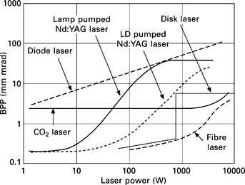
2.6 BPP of some lasers as a function of laser output power (from Katayama, 2009).
where f is the focal length (mm) and D is the input beam diameter at the lens (mm). Laser welding is normally performed using multi kW class lasers. In this high power range, BPP in the rod type Nd:YAG laser significantly increases with the output power due to thermal distortion of the cylindrical laser medium. On the other hand, CO2 lasers can keep high beam quality even in the high power range. The BPP is almost similar to that in disk and fibre lasers.
Relatively lower machine cost per unit power is also an advantage of the CO2 laser. In heavy section welding, the welding phenomenon is relatively more stable in CO2 laser welding compared with disk and fibre laser welding.
Most of the disadvantages in CO2 laser welding are caused by the long wavelength (10.6 μm) of the laser beam. Common transparent materials such as glass and quartz are opaque to 10.6 μm wavelength laser radiation. Therefore, optical fibre delivery systems cannot be used. The laser beam must be transferred to the workstation by reflection using mirrors. Accurate beam alignment is required and flexibility of the laser welding is limited for practical purposes. This is the biggest disadvantage of CO2 laser welding. In addition, special and expensive materials such as zinc selenide (ZnSe) must be used for optics such as windows and lenses.
2.4 Laser-materials interactions
2.4.1 Absorption of laser energy on material surfaces
When the laser beam irradiates materials, some of the energy is reflected on the material surface. The absorptivity may depend on the kind of materials, surface condition, surface temperature and laser wavelength. Table 2.1 shows the absorptivity of some materials at room temperature for three wavelengths corresponding to CO2 laser (10.6 μm), Nd:YAG laser (1.06 μm) and short wavelength laser (300–600 nm) irradiation (Modest, 2001). The absorptivity generally tends to decrease with the wavelength. Only a small amount of CO2 laser energy is absorbed on the metal surface. Conversely, CO2 laser beams are significantly absorbed on most ceramics surfaces.
Table 2.1
Absorptivity of some materials for three wavelengths at room temperature (adapted from Modest, 2001)
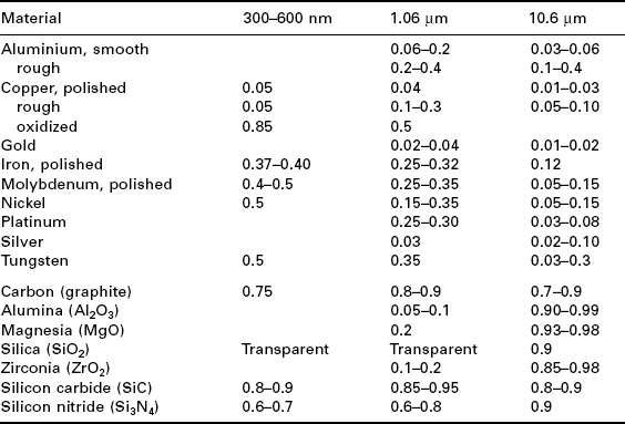
The absorptivity normally increases with temperature. During laser welding, formation of molten pools enhances the absorption of laser energy. In keyhole mode laser welding, multiple reflection of the laser beam on a narrow and deep keyhole wall significantly increases energy transfer efficiency due to multiple absorption. Thus, the absorptivity does not affect so much the weld geometry once the keyhole is formed.
2.4.2 Absorption of laser energy in laser-induced plasma
Attenuation of incident laser energy by inverse Bremsstrahlung
During CO2 laser welding, a high power density laser beam irradiates the materials and causes intense evaporation. The laser beam interacts with the vapour jet and a laser plume or laser-induced plasma which is formed just above and inside the keyhole. The laser energy is absorbed in the plasma by inverse Bremsstrahlung and it attenuates the incident laser energy. The laser energy passed through the plasma I(W) with length x(m) and absorption coefficient α (m–1) is
where I0 is the incident laser energy (W). For hot plasma (hω/π << kTe), the absorption coefficient α(m–1) is given (Hughes, 1975; Allmen and Blatter, 1995) by:
where ω is angular frequency, ni and ne are density of electron and ion (m–3), respectively, Z is the ion charge number, e is electron charge (C), K is Boltzmann’s constant (JK–1), Te is the electron temperature (K), h is Planck’s constant (Js), c is the speed of light (ms–1), ε0 is the dielectric constant (C/Vm), and me is the mass of electron [kg]. From eq. [2.3], we can know that the absorption coefficient α is roughly proportional to square of the wavelength λ. Therefore, attenuation of laser energy is more significant in CO2 laser welding than solid-state laser welding and this affects the weld geometry.
Assuming that the plasma is in local thermodynamic equilibrium (LTE) and Z = 1, the absorption coefficient α for CO2 laser beam is given by:
Equation [2.4] indicates that a higher absorption coefficient is obtained for a higher degree of ionization (higher electron density ne) at lower electron temperature Te. The tendency of ionization is determined by the ionization potential. Atoms are more easily ionized with decreasing ionization potential of the element. Table 2.2 shows ionization potentials of some elements. In the inert gas, helium has the highest ionization potential and it is not ionized even in high power CO2 laser welding. Therefore, helium is sometimes used as a shielding gas of high power CO2 laser welding to prevent attenuation of the incident laser energy by plasma absorption.
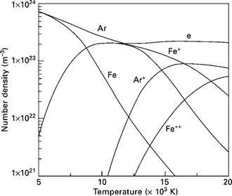
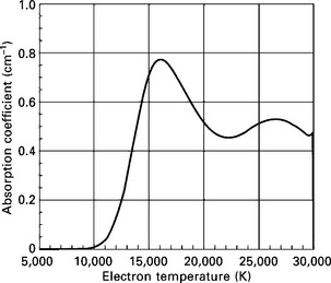
As the ionization potential of metals is about half that of argon, metals are more easily ionized than inert gases. Figure 2.7 shows the composition of Ar-50 vol% Fe plasma at various temperatures. Iron starts to ionize at lower temperature and shows the maximum ion density at around 10,000 K due to low ionization potential, whereas argon ion density has a peak at a higher temperature of around 17,000 K. Figure 2.8 shows the absorption coefficient of argon plasma as a function of the temperature. The absorption coefficient has a peak at around 17,000 K, because the argon ion and electron density has a maximum value at this temperature.
In low power CO2 laser welding, only metals are ionized due to low plasma temperature, but the shielding gas is also ionized in high power laser welding. Figure 2.9(a) shows the laser-induced plasma formed during 5 kW CO2 laser welding with a coaxial Ar shielding. Monochromatic images of some spectrum lines such as argon atom (Ar I: 696.5 nm), argon ion (Ar II: 480.7 nm) and iron atom (Fe I: 381.5 nm) are also shown in Fig. 2.9(b)–(d) (Tsukamoto et al., 1999). Argon ion is clearly observed at the centre of the plasma, where the laser beam interacts directly with the plasma as shown in Fig. 2.9(c). It is surrounded by argon atoms as shown in Fig. 2.9(b). Thus, the gas plasma is normally formed above the workpiece in high power CO2 laser welding. On the other hand, the metal plasma is mainly formed inside and just above the keyhole as shown in Fig. 2.9(d).
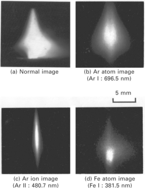
2.9 Monochromatic photographs of laser-induced plasma formed during CO2 laser welding (5 kW, fd = − 2 mm, Ar shielding: 40 L/min): (a) normal image, (b) argon atom image (Ar I: 696.5 nm), (c) argon ion image (Ar II: 480.7 nm), (d) iron atom image (Fe I: 381.5 nm).
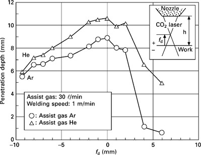
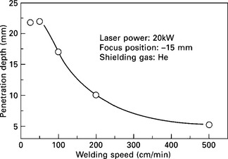
Formation of the plasma significantly affects the weld geometry. Figure 2.10 shows the penetration depth in 5.4 kW CO2 laser welding with different shielding gases. The penetration depth is always lower in argon shielding. It is caused by attenuation of incident laser energy in argon plasma, whereas helium is not ionized during welding due to high ionization potential. Figure 2.11 shows the penetration depth as a function of the welding speed in 20 kW CO2 laser welding with helium shielding. The penetration depth increases with decreasing welding speed, but it saturates below 50 cm/min. This phenomenon is not observed in solid-state laser welding. The salutation of the penetration depth in CO2 laser welding is attributed to attenuation of laser energy by metal plasma formed inside the keyhole.
Plasma diagnostics
From Eq. [2.4], the absorption coefficient in the plasma is a function of the electron density ne and electron temperature Te. ne is determined by Te with the assumption of LTE. Therefore, a lot of research work has been carried out to measure Te during CO2 laser welding by spectroscopic methods (Rockstroh and Mazumder, 1987; Mazumder et al., 1987; Sokolowski et al., 1988, 1989; Poueyo et al., 1992; Miyamoto and Maruo, 1992; Verwaerde and Fabbro, 1995; Tsukamoto et al., 1996). The intensity of a thermally excited spectral line εnm is given by:
where Anm is Einstein transition probability of the line (s–1), n0 is the density of atom or ion (m–3), gn is statistical weight of the term n, Z(T) is the partition function, En is the energy level (J). From Eq. [2.5], Te can be determined by measuring the absolute value of spectral intensity εnm with the assumption of LTE. This is called the ‘absolute spectral intensity method’. Te can also be determined by the ratio of the spectral intensity εnm of same species in different spectral lines. This is called the ‘relative intensity method’. In this case, assumption of LTE is not necessary. From Eq. [2.5], where K is a constant. If we measure some spectral intensities of the same species with different spectral lines and plot ln(εmnλ/Anmgn) as a function of En, we can know the electron temperature Te from the gradient. This is called the the ‘Boltzmann plot method’ and is often used to determine the electron temperature in the plasma.
Figure 2.12 shows the temperature profile of the plasma formed during 5 kW CO2 laser welding with argon shielding flowed from the coaxial nozzle at 30 L/min (Tsukamoto et al., 1999). The focal point is located just on the sample surface. A peak temperature of around 22,000 K can be seen at the centre of the plasma, which corresponds to the argon ion enriched region in Fig. 2.9(c) due to direct interaction of the laser beam with the plasma. This temperature is similar to the peak temperature of argon TIG arc.
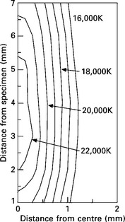
2.12 Temperature profile of argon plasma formed above the workpiece during CO2 laser welding (5 kW, fd = 0 mm, Ar shielding: 30 L/min).
If we know the electron temperature distribution as shown in Fig. 2.12, we can calculate the electron density with the assumption of LTE and the absorption coefficient using Eq. [2.4] at any part of the plasma. As a result, we can estimate the absorptivity of the plasma under various welding conditions.
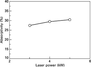
Figures 2.13–2.15 show the absorptivity for various welding conditions (Tsukamoto et al., 1999). The absorptivity gradually increases with the laser power as shown in Fig. 2.13. The flow rate of the shielding gas does not exert a great influence on the absorptivity. The maximum temperature slightly decreases from 22,000 to 20,000 K with increasing the flow rate from 20 to 60 L/min as shown in Fig. 2.14(a). In this temperature range, the absorption coefficient decreases with temperature as shown in Fig. 2.8, but the plasma size also decreases with the flow rate as shown in Fig. 2.14(b). As a result, the absorptivity shows approximately a constant value over a wide range of flow rates. The absorptivity is most significantly affected by the beam focusing condition. The maximum temperature is not affected significantly by the defocus distance fd as shown in Fig. 2.15(a). The absorptivity, on the other hand, increases significantly as the focal point shifts upward from inside to above the sample as shown in Fig. 2.15(b). It is caused by expanding the plasma with fd. The plasma size increases as the power density increases near the plasma-forming area.
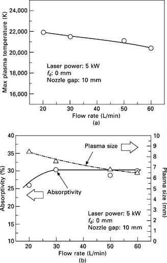
2.14 Maximum plasma temperature, plasma size and absorptivity for various flow rates of argon shielding gas: (a) maximum plasma temperature, (b) plasma size and absorptivity.
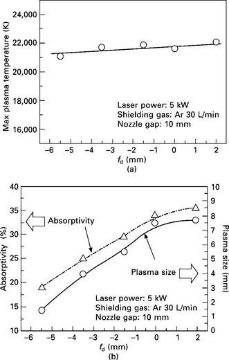
2.15 Maximum plasma temperature, plasma size and absorptivity for various defocus distances fd: (a) maximum plasma temperature, (b) plasma size and absorptivity.
To suppress attenuation of the incident laser energy by the plasma, flow of the inert gas with high ionization potential is effective. A helium or heliumargon mixture is normally used as a shielding gas in high power CO2 laser welding. In the welding variables, the effect of beam focusing condition is most significant. To suppress the plasma absorption, power density just above the sample surface should be reduced by selecting the negative defocused distance.
Plasma monitoring
The plasma is generated and maintained by evaporation of materials and absorption of laser energy through inverse Bremsstrahlung. Therefore, the plasma emission includes a lot of information on the welding phenomena and it is sometimes used to monitor the welding conditions, welding phenomenon and formation of defects.
Figure 2.16(a) and (b) show one typical example of the in-process monitoring of penetration depth using the plasma signal (Mori and Miyamoto, 1997). Partial and full penetration CO2 laser welding was carried out on 1.6 and 4 mm thick mild steels. Plasma emission was detected by two photodiodes located at different angles of 75° and 5° as shown in Fig. 2.16(a). The 5° photodiode detects the emission from only the near surface plasma (A in Fig. 2.16(a)), whereas the 75° photodiode signal contains the emission from the keyhole plasma and near surface plasma (A+B in Fig. 2.16(a)). Figure 2.16(b) shows the mean square value of the plasma signals in a frequency range of 2–4 kHz as a function of the welding speed. The full penetration region is shaded in the graph. It is clear that full or partial penetration welding can be distinguished from the 75° photodiode signal. The mean square value of the plasma signal is much higher in full penetration than that in partial penetration.
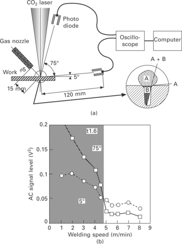
2.16 In-process monitoring of penetration depth by plasma emission signal (from Mori and Miyamoto, 1997): (a) schematic diagram of the experimental setup, (b) mean square value of plasma signal as a function of welding speed (plate thickness: 1.6 mm).
2.5 Welding phenomena and formation of defects
2.5.1 Pressure balance on keyhole wall
In keyhole mode laser welding, a narrow and deep keyhole is formed by evaporation of materials. The laser energy can be supplied inside the materials through the keyhole and then narrow and deep weld penetration is formed. However, the keyhole is basically unstable, if the length is larger than the circumference (l > 2πr, l: keyhole depth, r: keyhole radius). The keyhole tends to be closed at some parts along the penetration. It is called the Rayleigh instability (Rayleigh, 1945; Chandrasekhar, 1961). When the keyhole is being closed by instability, the laser beam strongly interacts with the molten metal at the closing part and opens the keyhole again by high recoil pressure as shown in Fig. 2.17. Thus, the keyhole oscillates in the radial direction while it is maintained during deep penetration laser welding and it sometimes causes weld defects.
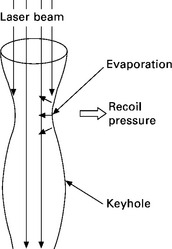
2.17 Keyhole behaviour during laser welding. Closure of the keyhole by Rayleigh instability is prevented by direct irradiation of the laser beam.
Statically, the keyhole is maintained by the following pressure balance acting on the keyhole wall.
where Pabl is the recoil pressure (N/m2), δPg is the excess vapour pressure (δPg = Pv – P0, Pv: vapour pressure, P0: atmospheric pressure) (N/m2), Pσ is the surface tension pressure (Pσ = σ/r, σ: surface tension (N/m), r: keyhole radius (m)) (N/m2) and Ph is the hydrostatic pressure (N/m2). Pressure terms on the left side act to open the keyhole and those of the right side act to close the keyhole. During welding, these pressures are balanced at any parts on the keyhole wall. In CO2 laser welding, the metal vapour is partially ionized and forms the plasma inside the keyhole. The plasma temperature is higher than that in the solid-state laser welding due to the high absorption coefficient of the CO2 laser beam. High temperature plasma formed inside the keyhole may increase δPg and the keyhole radius may increase in CO2 laser welding. This may be one of the reasons why CO2 laser welding is stable.
2.5.2 Defect formation in partial penetration CO2 laser welding
Stability of the keyhole significantly affects the formation of defects. In heavy section laser welding, formation of the porosity is one of the major problems for practical applications. Especially in partial penetration welding, the porosity tends to be formed more frequently as shown in the longitudinal section of Fig. 2.18. Figure 2.19 shows an in-situ x-ray transmission keyhole image during partial penetration CO2 laser welding of C-Si-Mn steel. The image is taken by a high-speed video camera while a micro-focused x-ray is irradiated from the side of the sample. Bubble formation is clearly observed at the keyhole tip (Matsunawa et al., 1997; Matsunawa, 2001; Katayama et al, 1997; Tsukamoto et al, 2001, 2002). The bubbles formed at the keyhole tip combine with each other and most of them remain as porosity after solidification. Figure 2.20 shows the bubble formation process near the keyhole tip. During welding, a neck is formed near the keyhole tip (Fig. 2.20(c)) and then the keyhole is closed there by surrounding molten metal (Fig. 2.20(d)). The closure of the keyhole is normally prevented by irradiation of the laser beam to the closing molten metal as described above. However, if the keyhole fluctuates and laser/molten metal interaction is significant in the keyhole, a lot of laser energy is consumed by the interaction and it reduces the laser power density near the root to less than the critical value to maintain the keyhole. As a result, the keyhole is closed near the root by Rayleigh instability. This result indicates that stabilization of the keyhole should be effective in preventing the porosity.
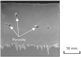
2.18 Longitudinal section of CW CO2 laser welds (C-Si-Mn steel, 20 kW, fd = 1.0, 1 m/min, shielding gas: He, 50 L/min).
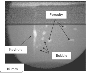
2.19 In-situ x-ray transmission image of keyhole (same condition as Fig. 2.18).
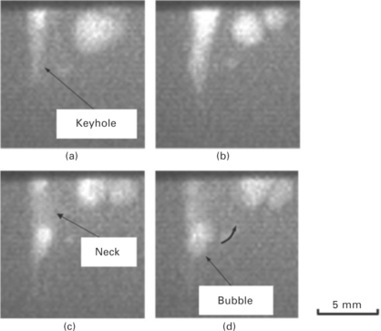
2.20 In-situ x-ray transmission images near the keyhole tip. A bubble is formed by closure of keyhole tip: (a) 0 ms, (b) 7 ms, (c) 16 ms, (d) 17 ms.
Nitrogen shielding is normally used to prevent the porosity in high Cr stainless steel welding (Ishide et al., 1992), because the solubility of nitrogen increases with Cr concentration. Bubbles are not formed during welding by dissolving nitrogen in the molten pool. However, nitrogen shielding is not possible in very high power CO2 laser welding due to significant attenuation of laser energy by large nitrogen plasma. Also nitrogen shielding is not effective in laser welding of carbon steels, because the solubility of nitrogen is quite low in carbon steels.
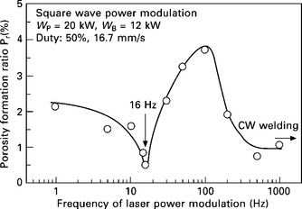
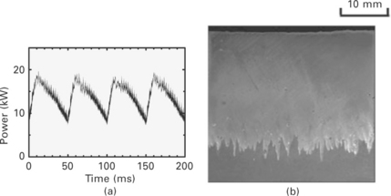
The other porosity prevention method is stabilization of the keyhole by laser power modulation (Tsukamoto et al., 2002). The porosity is effectively suppressed by optimizing the modulation conditions. Figure 2.21 shows the porosity formation ratio Pr (ratio(%) of the sum of porosity area to the weld metal area) in CO2 laser welding of C-Si-Mn steel as a function of the power modulation frequency. Laser power is modulated with square wave at the peak and base powers of 20 and 12 kW, respectively. The porosity is clearly suppressed at 16 Hz in this condition. This optimum modulation frequency coincides well with the natural frequency of the molten pool oscillation. Stabilization of the keyhole was confirmed under the optimum frequency by an in-situ x-ray transmission imaging system. The porosity suppression effect is further enhanced by optimizing the waveform. Almost all pores are prevented by optimization of the waveform and frequency as shown in Fig. 2.22 (a) and (b).
2.5.3 Defect formation in single pass full penetration CO2 laser welding
In single pass full penetration laser welding, the porosity caused by keyhole instability is less likely to occur, but it is formed via a different mechanism. A typical example is shown in Fig. 2.23, where full penetration laser welding was carried out on C-Si-Mn steel without back shielding (Tsukamoto et al., 2003). Figure 2.24(a) shows the in-situ x-ray transmission image for full penetration CO2 laser welding of 15 mm thick C-Si-Mn steel without back shielding. Bubbles are generated in the molten metal just behind the keyhole. This is caused by supersaturated nitrogen in the molten pool. During full penetration laser welding, the excessive laser energy, which penetrates through the steel plate, forms air plasma on the back surface as shown in Fig. 2.24(b). The plasma contains a lot of monatomic nitrogen, which can much more easily dissolve in the molten steel than diatomic nitrogen (Dong et al, 2004). The nitrogen concentration in the molten pool then increases near the bottom, and if it exceeds the solubility of diatomic nitrogen, bubbles are formed in the molten metal.
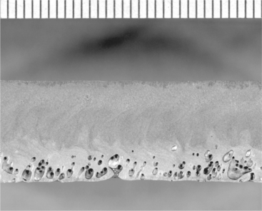
2.23 Longitudinal section of CO2 laser welds of 11 mm thick C-Si-Mn steel without back shielding (11 kW, fd = 0 mm, 1 m/min).
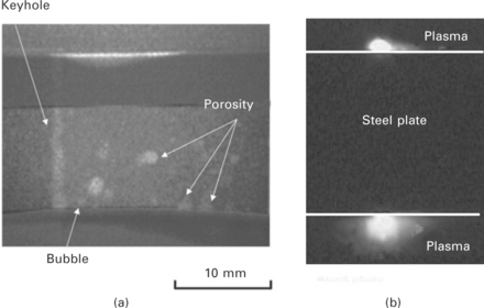
2.24 Single pass full penetration CO2 laser welding behaviour of 15 mm thick C-Si-Mn steel (20 kW, fd = 0 mm, 1 m/min): (a) in-situ x-ray transmission image; bubbles are generated in the molten pool just behind the keyhole, (b) formation of air plasma just below the back surface.
The inert gas back shielding can effectively prevent this type of porosity. However, the solidification crack is easily formed accompanied by the locally expanded weld cross section, which is very susceptible to the solidification crack, as shown in Fig. 2.25(a) (Tsukamoto et al, 2003). This abnormal weld cross section is caused by a keyhole perturbation. During welding, the inert gas enters the keyhole from the back surface and expands in the keyhole as shown in the x-ray transmission image of Fig. 2.25(b). This local expansion of the keyhole forms the abnormal cross section, leading to occurrence of the solidification crack. Addition of a small amount of denitrification elements, such as aluminium, is effective to prevent the porosity without forming the solidification crack (Tsukamoto et al., 2004). 0.8 mass% of aluminium is enough to prevent the porosity during the full penetration welding of 15 mm thick carbon steels as shown in Fig. 2.26. In this case, the inert gas back shielding is not necessary. The solidification crack then does not occur in the weld metal.
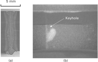
2.25 Formation of hot cracking susceptible cross section and keyhole behaviour during CO2 laser full penetration welding of 15 mm thick C-Si-Mn steel with argon back shield (16 kW, fd = 0 mm, 1 m/min): (a) transverse cross section of laser welds, (b) in-situ x-ray transmission image of keyhole.
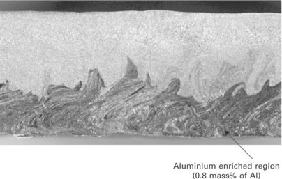
2.26 Longitudinal section of laser welds. Porosity formation is prevented by coating 200 mm thick aluminium on the back surface of the base metal prior to the welding.
Addition of nickel and carbon is also effective in suppressing the porosity (Tsukamoto et al., 2006). With increasing the carbon or nickel concentration in the base metal, the solidification mode changes from fully ferritic to ferritic-austenitic or austenitic-ferritic. Higher solubility of nitrogen in the austenite phase suppresses the porosity formation in high carbon or nickel steels.
Recently, high power brilliant lasers such as fibre and disk lasers were developed. These lasers are very attractive tools to weld heavy section plates. However, there are some problems to be solved (Rominger, 2011). Spatter generation, melt-through and underfill are more likely to occur and the optimum welding conditions are narrower in some cases compared with CO2 laser welding. The mechanism of the different welding phenomenon between CO2 and brilliant laser welding is not yet well understood. High temperature keyhole plasma formed in CO2 laser welding may be one of the factors to stabilize the keyhole due to increase in δPg in Eq. [2.8].
2.6 Industrial applications of CO2 laser welding
Multi-kW class high power CO2 lasers, which are capable of keyhole mode welding, were developed in the mid-1970s. Since then, CO2 laser welding has been applied in a variety of industries. In this section, some examples of the industrial applications are introduced.
2.6.1 Automotive industry
From the late 1970s to 1980s, application of CO2 laser welding started in the automotive industry. Various parts of powertrains including transmission gears, hubs and shafts were welded by CO2 lasers (Petring, 2004). High productivity, low heat input and low distortion are the main advantages of laser welding compared with the other processes. CO2 lasers are still being used in these applications.
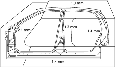
Laser welded tailored blanks are widely used in manufacturing parts of the car body such as doors, front and side panels, side beams and wheel arches. As shown in Fig. 2.27, flat metal sheets with different gauge, strength and coating are joined by laser welding prior to forming and trimming. Mixture of different sheet metals allows a reduction in weight, number of components and total manufacturing cost and an improvement in crash energy management. This technique has been used since the mid-1980s. Most linear welding lines are equipped with 5–10 kW CO2 lasers. On the other hand, Nd:YAG, fibre or disk lasers are used mainly in non-linear welding.
Application of laser welding in the body shop started in the mid-1980s. 5 kW class CO2 lasers were installed by some automobile companies to weld body in white such as joining of the roof with the side frames. However, usage of CO2 lasers decreased in the late 1990s due to installation of high power Nd:YAG lasers with robots, which are capable of three-dimensional laser welding.
Installation of remote laser welding started in the early 2000s to produce car body components. In this system, the laser spot quickly moves by high-speed scanning mirrors to weld some parts very quickly. A high beam quality laser is required to cover the wide welding area with a long focal length of normally greater than 1 m. A slab CO2 laser was first used to attain a high beam quality laser beam. Reduction of the tact time and high productivity are the main advantages. Due to progress of high power disk and fibre lasers with high beam quality, a new remote welding system combined with a robot was developed. More flexible and faster welding was achieved using fibre and disk lasers. This system is called ‘remote welding on the fly’ and is used widely.
2.6.2 Aircraft industry
Airbus applied CO2 laser welding of the stringer to skin sheets for aircraft fuselage panels in the early 2000s (Schumacher et al., 2002; Vollertsen et al., 2004). This was achieved by developments in laser welding systems and weldable Al-Mg-Si-Cu alloy. Instead of conventional riveting, the stringers are joined to the skin sheet by simultaneous laser welding from both sides as shown in Fig. 2.28. Al-12% Si filler wire is used to avoid hot cracking. Weight reduction, high productivity, improvement of corrosion resistance and high cost performance are the main advantages of replacing the conventional riveting process with laser welding.
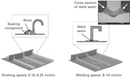
2.28 Comparison of riveting and laser welding for the skin to stringer joint (from Vollertsen et al., 2004).
2.6.3 Shipbuilding industry
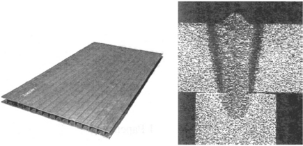
The first laser welding application in the shipbuilding industry was the manufacture of sandwich panels by Meyer Werft in the mid-1990s (Roland et al., 2004). It was produced by stake welding of flat panels up to 10 mm in thickness to webs by 12 kW CO2 laser as shown in Fig. 2.29. Weight reduction with high strength and stiffness and low distortion can be attained.
In Europe, guidelines for approval of CO2 laser welding was laid down following a number of national and EC projects in the mid-1990s. This accelerated the applications of laser welding in the shipbuilding industry. Long straight butt and fillet welding lines of thick steel plates were installed at Odense Steel Shipyard (Sellerup, 1999), Fincantiaeri (Manzon, 1998) and Blohm & Boss (Kahl, 1998) in the late 1990s. The line consists of a gantry equipped with high power CO2 lasers from 12 to 18 kW. The line includes monitoring and feedback control systems, edge preparation and machining and/or wire feeding systems. A most attractive advantage of installing high power laser is reduced distortion, which significantly reduces total man-hour consumption for additional straightening operations. Improvement of mechanical accuracy enables automation of the production line and high productivity was realized. Meyer Werft installed four laser/GMA hybrid welding stations from the late 1990s to early 2000s (Roland et al, 2004) and now the amount of laser hybrid welds in a large cruise ship is close to 50% of the total weld length.
Recently, fibre and disk lasers have been installed by some shipbuilding companies due to flexibility of fibre delivery systems. However, CO2 laser has also been installed in new lines due to stability of the welding phenomena.
2.6.4 Steel industry
From the early 1980s, the steel industry installed 5–10 kW CO2 lasers for welding of hot or cold rolled steel sheets in continuous coil welding lines. Joint interface property was much improved by replacing flash welding with laser welding. In the early 2000s, two 45 kW class CO2 lasers were applied to welding of hot steel bars of 30 mm thickness at continuous finish rolling lines (Minamida, 2002).
CO2 lasers were also installed for manufacturing small diameter stainless steel welded pipes to improve productivity in the early 1980s. CO2 lasers are still being used in this application field. For manufacturing pipes with medium diameter and heavy wall thickness, 25 kW CO2 laser welding combined with high frequency induction coil preheating was applied in the mid-1990s (Hayashi et al., 1996; Ono et al., 2001).
2.6.5 Other applications
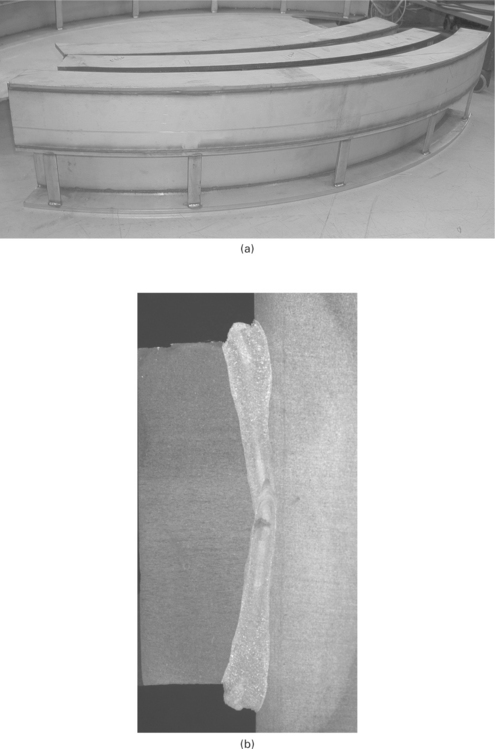
High power CO2 lasers have been used to fabricate parts of some chemical plants such as the plant for petroleum refining. A large skirt made by thick stainless steels is fabricated by CO2 lasers as shown in Fig. 2.30(a). T-beams are also fabricated by CO2 lasers as shown in Fig. 2.30(b), where 25 mm thick stringer is welded to the web. Components of plasma reactor used for production of compound, semiconductor and nanomaterials such as carbon nanotube are manufactured by CO2 laser welding with low distortion and no weld defects. CO2 lasers are also used to weld a pipe to a blade for skate shoe runners.
2.7 Future trends
CO2 laser welding has been applied in a variety of industries since the mid-1970s. In the early 1990s, multi-kW class Nd:YAG lasers were developed. It has a great advantage in its fibre-optic delivery system, although the beam quality of rod-type YAG lasers is worse than that of CO2 lasers. Therefore, applications of YAG laser welding immediately expanded mainly in the field of thin plate welding.
In the mid-2000s, high power brilliant lasers such as disk and fibre lasers were developed. As the beam quality of these lasers is very high, application fields of these lasers have been expanding not only in thin plate welding but also in heavy section welding. The development of these lasers significantly reduced the usage of CO2 laser welding. However, some problems such as melt through, spattering and narrow optimum conditions still remain to be solved in heavy section fibre and disk laser welding. CO2 laser welding will continue to be used in some areas unless these problems are not solved.
2.8 Acknowledgements
The author is grateful to Mr M. Dahmen, Fraunhofer Institute for Laser Technology, for his useful information on practical applications and CO2 welding phenomena.
2.9 References
Allmen, M., von Blatter, A. Laser Beam Interaction with Materials, 2nd ed. Berlin: Springer; 1995.
Chandrasekhar, S, Hydrodynamic and Hydromagnetic Stability 1961. Oxford: Clarendon Press, 1961.
Davis, J., Slab lasers edited byReady J. F., Farson D. F., Orlando F. L., eds. LIA Handbook of Laser Materials Processing. Laser Institute of America, 2001.
Dong, W., Kokawa, Y., Tsukamoto, S., Sato, Y. S., Ogawa, M. Mechanism governing nitrogen absorption by steel weld metal during laser welding. Metall. Mater. Trans. B. 2004; 35B:331–338.
Hayashi, T., Inaba, Y., Matuhito, Y., Yamada, T., Kudo, T, Development of high power welding process for pipe D. Proc. ICALEO. 1996; 1996:132–140.
Hughes, T. P. Plasma and Laser Light. In: The Institute of Physics. Bristol: Adam Hilger; 1975:39–54.
Ishide, T., Nagura, Y., Matsumoto, O., Nagashima, T., Kidera, T., Yokoyama, A., High power YAG laser welded sleeving technology for steam generator tubes in nuclear power plants. Proc. LAMP. 1992; 1992:957–962.
Kahl, A., Compact shipyard DVS195. Proc. Intel. Conf. IIW’ 1998; 98:60–63.
Katayama, S. ‘Laser welding for manufacturing innovation’, J. Japan Welding Society. 2009; 78:682–692. [(in Japanese)].
Katayama, S., Seto, N., Kim, J. D., Matsunawa, A., Formation mechanism and reduction method of porosity in laser welding of stainless steel G. Proc. ICALEO’ 1997; 97:83–92.
Manzon, L., Welding in shipbuilding industry May. Welding Review International. 1998:6–8.
Matsunawa, A. Problem and solutions in deep penetration laser welding. Sci. Technol. & Weld Joining. 2001; 6:351–354.
Matsunawa, A., Kim, J. D., Katayama, S., Porosity formation in laser welding G. Proc. ICALEO’ 1997; 97:73–82.
Mazumder, J., Rockstroh, T. J., Krier, H. Spectroscopic studies of plasma during CW laser gas heating in flowing argon. J. Appl. Phys.. 1987; 62:4712–4718.
Minamida, K. ‘High power laser applications in Nippon Steel Corporation’, Proc. SPIE. 2002; 4831:402–410.
Miyamoto, I., Maruo, H., Spacial and temporal characteristics of laser-induced plasma in CO2 laser welding. Proc. LAMP’ 1992; 92:311–316.
Modest, M. F., Reflectivity and absorptivity of opaque surface edited byReady J. F., Farson D. F., Orlando F. L., eds. LIA Handbook of Laser Materials Processing. Laser Institute of America:, 2001:182.
Mori, K., Miyamoto, I. ‘In-process monitoring of laser welding by the analysis of ripples in the plasma emission’, J. Laser Application. 1997; 9:155–159.
Ono, M., Shinozaki, T., Shinbo, Y., Sekine, Y., Iwasaki, K., Takahashi, M. ‘Development of high power pipe welding process’, Quarterly J. Japan Welding Society. 2001; 19:233–240.
Petring, D. ‘Laser applications in European automotive manufacturing: Historical review and recent trends’, J. Japan Welding Society. 2004; 73:7–14.
Poueyo, A., Deshors, D., Fabbro, R., de Frutos, A. M., Orza, J. M., Study of laser induced plasma in welding conditions with continuous high power CO2 laser. Proc. LAMP’ 1992; 92:323–328.
Rayleigh, J. W. S. The Theory of Sound; Vol. 2. Dover Publications, New York, 1945.
Rockstroh, T. J., Mazumder, J. Spectroscopic studies of plasma during CW laser materials interaction. J. Appl. Phys.. 1987; 61:917–923.
Roland, F., Manzon, L., Kujala, P., Brede, M., Weitzenbock, J. ‘Advanced joining techniques in European shipbuilding’, J. Ship Production. 2004; 20:200–210.
Rominger, V. ‘High-performance laser welding – a comparison of CO2 lasers and high brilliance solid-state lasers’,. Laser Tech J.. 2011; 8:32–35.
Schumacher, J., Zerner, I., Neye, G., Thormann, K., Laser beam welding of aircraft fuselage panels’. Proc. ICALEO. 2002; 2002:.
Sellerup, M., Laser welded ship are afloat. Industrial Laser Solution, April. 1999:20–22.
Sokolowski, W., Herziger, G., Beyer, E. Spectral plasma diagnostics in welding with CO2 lasers. Proc. SPIE’88. 1988; 1020:96–102.
Sokolowski, W., Herziger, G., Beyer, E. Spectroscopic study of laser induced plasma in the welding process of steel and aluminium. Proc. SPIE’89. 1989; 1132:288–295.
Tsukamoto, S., Hiraoka, K., Asai, Y., Irie, H., Yoshino, M. Characteristics of stably induced laser plasma. Proc. ICALEO’96. 1996; 81:B76–B85.
Tsukamoto, S., Asai, Y., Tanaka, H., Shida, T. High-speed measurement of plasma temperature in CO2 laser welding. Proc. ICALEO ‘99. 1999; 87:D73–D82.
Tsukamoto, S., Kawaguchi, I., Arakane, G., Honda, H., Suppression of porosity using pulse modulation of laser power in 20 kW CO2 laser welding. Proc. ICALEO. 2001; 2001:C1702.
Tsukamoto, S., Kawaguchi, I., Arakane, G., Honda, H. ‘Keyhole behaviour in high power laser welding’, Proc. SPIE, 1st Intl. Symp. on High Power Laser Macroprocessing. 2002; 4831:251–256.
Tsukamoto, S., Arakane, G., Kawaguchi, I., Honda, H., Keyhole behaviour in high power laser welding of thick steel plates. Proc. ICALEO. 2003; 2003:A176–A183.
Tsukamoto, S., Arakane, G., Honda, H., Kuroda, S., Formation mechanism and prevention of weld defects in full penetration laser welding of thick steel plates. Proc. ICALEO. 2004; 2004:104–110.
Tsukamoto, S., Arakane, G., Kojima, K., Otani, T., Ohkita, S., Effect of alloying elements on porosity formation in laser welding of heavy section steel plates. Proc. ICALEO. 2006; 2006:26–33.
Verwaerde, A., Fabbro, R. Experimental study of continuous CO2 laser welding at subatmospheric pressure. J. Appl. Phys.. 1995; 78:2981–2984.
Vollertsen, F., Schumacher, J., Schneider, K., Seefield, T., Innovative welding strategies for the manufacture of large aircraft. Proc. IIW Intl. Conf. 2004; 2004:.

