Introduction: fundamentals of laser welding
Abstract:
This chapter describes characteristics of laser welding, features of main lasers used for welding, factors affecting weld penetration, laser welding phenomena including behavior of laser-induced plume, keyhole behavior and melt flows in a molten pool during laser welding. It also refers to welding defects and the recent trend for laser welding.
1.1 Characteristics of laser welding
Welding is the most versatile and realistic joining method applicable to the construction of products in every industrial field. A laser is a high-power-density heat source. Therefore, ‘laser welding’ is recognized as an advanced process to join materials with a laser beam of high-power, high-energy density. Representative power density profiles of laser, electron beam, plasma and arc, and the consequent weld bead geometries are schematically illustrated in Fig. 1.1.
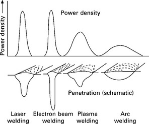
1.1 Power densities for typical welding heat sources, and geometry of weld beads obtained at respective densities.
The power density of a laser beam, which is equivalent to that of an electron beam, is much higher than that of arc or plasma. Consequently a deep, narrow keyhole is formed during welding with a high-power-density beam of laser or electron, and a deep, narrow penetration weld can be effectively produced. In electron beam welding, the chamber for a vacuum environment and X-ray protection should be used, and for steel plates, demagnetization treatment is required before welding. Arc and plasma welding cannot be employed in a vacuum; however, laser welding can be performed and a sound, deep weld bead can be produced in a similar way to electron beam welding, which is described in Section 1.5. Generally the travelling speed of laser welding is higher than those of arc and plasma welding.
Among all the welding processes, laser welding can produce a variety of joints of metals or plastics ranging from very thin sheets of about 0.01 mm thickness to thick plates of about 50 mm in the shielding gas such as helium (He), argon (Ar) or sometimes nitrogen (N2) under the air environment, and has gained great popularity as a promising joining technology with high quality, high precision, high performance, high speed, good flexibility and low distortion. 1–4 It can also achieve robotization, reduced manpower, full automation, and systematization in production lines. Consequently, applications of laser welding are increasing together with the development of novel laser apparatuses and joining processes. In order to properly apply pulsed or continuous wave (PW or CW) lasers to welding or joining, it is important to know the specifications and capability of laser apparatuses, the factors affecting weld penetration and welding defects, and the mechanisms and behaviour of welding as well as to evaluate the weldability of materials and the mechanical properties of welded joints. For further details on the contents of this chapter, see the references in Section 1.6.1–4
1.2 Lasers for welding
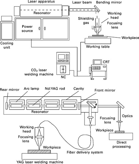
The kind and characteristics of the main lasers used for welding are summarized in Table 1.1. Typical CO2 and Nd:YAG laser systems are schematically represented in Fig. 1.2. CO2 lasers, 10.6 μm in wavelength, are developed as high beam quality and easy achievement of higher power, the maximum laser power reaches up to 50 kW, and 1–15 kW power levels are mainly utilized in welding of steels, automotive components, airplanes, ships, etc.
Table 1.1
Types and characteristics of laser for welding
| Types of laser | Laser characteristics |
| CO2 laser | Wavelength: 10.6 μm; far-infrared ray Laser media: CO2-N2-He mixed gas (gas) Average power [CW]: 50 kW (Maximum) (Normal): 1–15 kW |
| Lamp-pumped YAG laser | Wavelength: 1.06 μm; near-infrared ray Laser media: Nd3 +:Y3Al5O12 garnet (solid) Average power [CW]: 10 kW (cascade-type max & fiber-coupling max) (Normal): 50 W–7 kW (Efficiency: 1–4%) |
| Laser diode (LD) | Wavelength: 0.8-1.1 μm; near-infrared ray Laser media: InGaAsP, etc. (solid) Average power [CW]: 10 kW (stack-type max.), 15 kW (fiber-delivery max.) Merits: Compact, and high efficiency (20–60%) |
| LD-pumped solid-state laser | Wavelength: about 1 μm; near-infrared ray Laser media: Nd3 +:Y3Al5O12 garnet (solid), etc. Average power [CW]: 13.5 kW (fiber-coupling max.) [PW]: 6 kW (slab-type max.) |
| Disk laser | Wavelength: 1.03 μm; near-infrared ray Laser media: Yb3 +:YAG or YVO4 (solid), etc. Average power [CW]: 16 kW (cascade-type Max.) Merits: Fiber delivery, high brightness, high efficiency (15–25%) |
| Fiber laser | Wavelength: 1.07 μm; near-infrared ray Laser media: Yb3 +:SiO2 (solid), etc. Average power [CW]: 100 kW (fiber-coupling max.) Merits: Fiber delivery, high brightness, high efficiency (20-30%) |
The following inconvenient problems should be considered in CO2 laser welding:
• High power lasers should be delivered by mirrors but not by an optical fiber, and
• an Ar plasma, which reduces weld penetration depth, can be easily formed in Ar shielding gas.
Nd:YAG lasers, 1.06 μm in wavelength, can be delivered through an optical fiber, and are operated in CW or PW mode. PW lasers are used in welding of small parts such as battery cases, electric components, glass frames, etc. CW lasers of 2–7 kW power are employed for laser welding of tailored blanks, aluminum cars, Zn-coated steel sheets, stainless steel pipes and tanks, etc. Such lamp-pumped Nd:YAG lasers have a drawback of low electrical efficiency (the ratio of laser output to electrical input) of less than 4%. Therefore, the development of high power CO2 and YAG lasers has already been stopped. Instead, laser-diode (LD)-pumped solid-state (YAG) lasers have been developed up to 6–10 kW. However, the development of these lasers has also been stopped. Recently, more is expected of disk and fiber lasers in terms of high power, high efficiency and high beam quality than of lamp- or LD-pumped YAG lasers. Fiber-delivery, which is used for lamp- or LD-pumped Nd:YAG, diode, Yb:disk and Yb:fiber lasers, is representative of good flexibility.
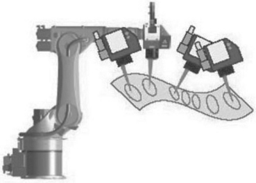
During the present century, thereafter, developments of lasers with high power and high beam quality have been concentrated upon laser diodes (LD) themselves, and LD-pumped disk and fiber lasers. LD has high electrical efficiency of 30–60%. Direct LD and fiber-delivered LD mounted to robots are used for welding of thin sheets of aluminum alloys, steels, stainless steels, plastics, etc., and for brazing of Zn-coated steels, etc. The drawback of LD is poor beam quality. High power, high electrical efficiency and high beam quality are achieved by disk and fiber lasers. Disk lasers and fiber lasers with a high electrical efficiency of 25% and maximum power of 16 kW and 100 kW, respectively, are commercially available. Their beam qualities are extremely high as the beam parameter products (BPP) are smaller than 10 mm · mrad. Disk and fiber lasers are both utilized as heat sources for remote welding, as shown in Fig. 1.3. Remote laser welding with a robot and a scanner is the most promising joining technology of high speed and high production rate. Further applications of these lasers are evolved to welding for electrical components, cars, trains, bridges, pipelines, ships, airplanes, etc.
1.3 Laser welding phenomena
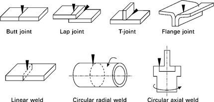
There are various kinds of laser-welded joints, as shown in Fig. 1.4. Butt- and lap-joints are commonly welded with PW or CW lasers. Typical phenomena during PW and CW laser welding are schematically illustrated in Fig. 1.5. Depending on the laser irradiation time and the power density, a spot or bead weld is formed in the morphology of a heat-conduction type or a keyhole type. When a laser beam is shot on the metallic plate, the absorption of laser energy is caused by the interaction against free electrons in the metal, the electrons transfer inside the band, and the interaction of moving electrons against metal lattice, defects, imperfection and potential perturbation. The temperature of the plate surface rises by the transfer from laser energy to thermal energy. The laser absorption increases slightly with an increase in the temperature in the solid and considerably above the melting temperature, and the temperature of the laser-irradiated area rises higher to the boiling temperature. A cavity or a keyhole is formed by recoil pressure due to evaporation. A coupling (absorption) coefficient of laser energy into the metal is schematically shown in Fig. 1.6. It increases according to the temperature and surface conditions. Since the laser absorption is extremely high due to multi-reflection inwards in the case of a keyhole formation, a keyhole type of deep penetration welding is regarded as an efficient joining process. A bright plume of evaporated metallic atoms and vapors is ejected from laser-irradiated part, especially a keyhole. Spattering of melt droplets, caused by a strong stream of the ejected plume, sometimes occurs from the inlet of a keyhole.
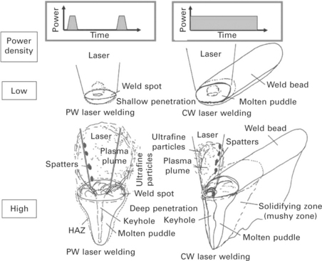
1.5 Schematic illustration of spot and bead welding phenomena with PW and CW laser, showing heat-conduction type shallow penetration and keyhole type deep penetration depending on laser power density.
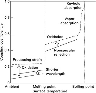
1.6 Coupling coefficient of laser energy into metal such as steel or aluminum alloy as a function of temperature.
The cross sections of laser weld beads in an aluminum alloy produced by CO2 laser welding at 5 kW in the shielding gas of He, N2 or Ar are shown in Fig. 1.7. The penetration depths at both welding speeds are shallower in the order of He, N2 and Ar. Examples of high speed video pictures during CO2 laser welding under the above-mentioned same conditions are shown in Fig. 1.8. Ar and N plasma are seen in the respective gases, although He plasma is not observed during welding. It is well understood that the decrease in CO2 laser weld penetration, especially in Ar or N2 gas, is attributed to the stable formation tendency and size of Ar and N plasma. In welding with high power CO2 lasers, He ratio of more than 50% is required to produce a deep penetration weld.
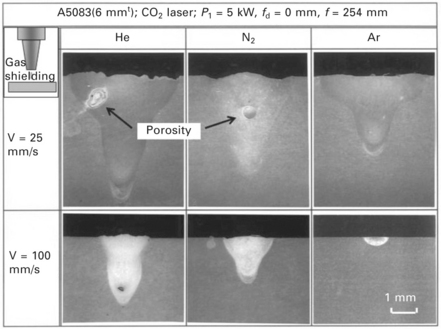
1.7 Cross-sectional photographs of CO2 laser weld beads, made at 25 and 100 mm/s in He, N2 and Ar coaxial shielding gas.
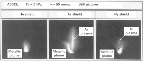
1.8 High speed video pictures of induced plume and gas plasma during CO2 laser welding in He, N2 and Ar coaxial shielding gas.
The formation situations of a laser-induced plume and/or plasma and their effects on the weld penetration are summarized in Fig. 1.9. The formation of Ar or N plasma is easy in the case of CO2 laser welding, while a laser-induced plume only is formed from a keyhole during YAG, disk and fiber laser welding. The interaction between the CO2 laser beam and the gas plasma is interpreted in terms of the absorption due to Inverse Bremsstrahlung, whose effect is about 100 times greater than that of YAG, disk or fiber laser. The temperature of a plume during welding with the laser of about 1 mm wavelength is estimated to be about 3,000–6,000 K depending on the high power density from about 1–1,000 kW/mm2. The effects of the plume are attributed to refraction due to the difference in density between the plume and the environment as well as Rayleigh scattering due to the formation of ultrafine particles. In the case of a tall plume and the consequent wide formation range of low refraction index, the weld penetration is drastically changed to be shallower from the keyhole type to the heat-conduction mode (at the focal point) due to the beam refraction and the downward shift of the focal point. As long as the height of the plume or low refractive index area (namely, the interaction length of the plume to a laser beam) is suppressed, a deep penetration weld can be produced.
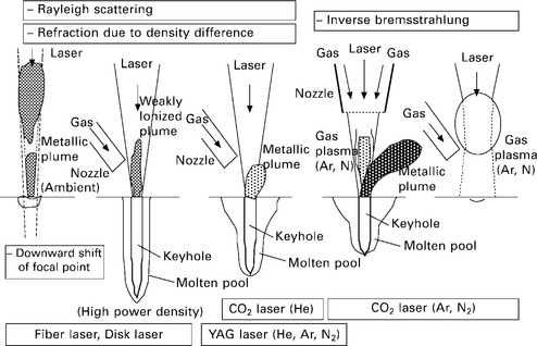
1.9 Schematic illustration of plume and plasma formation during laser welding and their respective physical effects on weld penetration in no gas or He, N2 and Ar shielding gas.
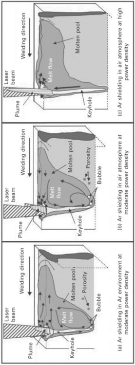
Melt flows in the molten pool and near the surface are interpreted by observing using an X-ray transmission in-situ imaging system and high speed video cameras. It is consequently understood that the weld penetration depth is determined chiefly by the keyhole depth and partly by the melt downward flow around the keyhole tip, as shown in Fig. 1.10. Melt flows of the surface in the molten pool are affected by the surface tension of the melt and the shear stream due to a plume ejected strongly from a keyhole inlet, resulting in the typical shapes of wide or narrow weld beads near the surface.
1.4 Laser weld penetration and welding defects
Small parts are made by spot welding with a pulsed laser. Deep penetration welds are easily formed with the increase in the pulse width near the focal point of a focusing lens. However, the maximum depths of sound laser spot welds should normally be less than 1.5 mm or 3 mm under controlled conditions, because porosity is easily formed especially even in the shallow weld with extremely short time irradiation and deep welds made with a laser of rectangular pulse shape. Pulse shaping of slowly rising and falling power is carried out to reduce spattering and porosity, respectively. These results and data will be demonstrated in Chapter 12.
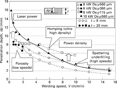
Deeply penetrated welds are effectively produced in high power CW laser welding. The penetration depths of stainless steel welds made with fiber lasers of different beam diameters at 6 and 10 kW in Ar shielding gas are shown in Fig. 1.11. In fiber laser welding at high power, deep penetration can be achieved even with Ar shielding gas, although the penetration is reduced due to Inverse Bremsstrahlung absorption by the formation of Ar gas plasma in the case of Ar shielding in CO2 laser welding.3 The penetration is shallower with the increase in the welding speed, and at high speeds, is deeper at higher power density of a smaller beam diameter. It is understood that the effect of laser power is more dominant at low speeds. The penetration is deeper at 10 kW than at 6 kW at a speed of less than 3 m/min (50 mm/s). At low welding speeds, porosity is easily formed, while at high speeds, porosity is prevented, but humping or spattering leading to underfilling occurs depending on the smaller or wider beam diameter, respectively. Under some conditions, welding defects such as porosity, cracks, humping, underfilling, and so on are easily formed. These mechanisms and preventive procedures will be described in Chapter 12.
1.5 Evolution of laser welding
In low and high vacuum, sound extremely-deep penetration welds can be produced, as shown in Fig. 1.12. The penetration depths of laser welds produced at low speeds in vacuum (under even low vacuum conditions) are comparable to those of electron beam welds.5 Laser welding is also applicable to the joining of similar or dissimilar plastics, dissimilar metals such as cast irons and steels, steels and aluminum alloys, or metals and plastics.6 It has recently been demonstrated that strong lap joints could be produced between steels and light metals such as aluminum or magnesium alloys, and in the same way between metals such as steels, stainless steels, aluminum alloys and titanium alloys, and engineering plastics such as PA (polyamide), PET (polyethylene terephthalate) and PC (polycarbonate).6 Figure 1.137 shows appearances of the laser lap joints between Type 304 stainless steel and PET plastic sheets before and after the tensile shear test. Small bubbles are formed in the melted plastic near the joint interface, and the elongation of the PET base plastic is demonstrated. Figure 1.147 exhibits cross-sectional SEM and TEM photographs near the interface of the joint at higher magnification and diffraction patterns from typical points. Cr2O3 type oxide film is identified, and it is observed that such oxide films always exist as an intermediate layer between plastic and metal for any combinations. The SEM and TEM images clearly show that a tight joint is produced, and that laser joining is performed partly by chemical or physical bonding of melted plastic on a thin oxide film covering the base metal. These results signify a feasibility of the production of a strong joint between metal and plastic sheet. Laser direct joining mechanisms of metal and plastic lap sheets are considered as follows: Laser is shot through the transparent plastic sheet or directly on the metal plate, and then the plate is heated to melt the plastic near the joint interface. Some bubbles are generated in order to force the activated melted plastic to flow over the metal surface. Tight joining of metal to plastic is performed through mechanisms of chemical, physical (van de Waals force) and mechanical (anchor effect) bonding. Laser joining of metal plate to GFRP (glass fiber reinforced plastics; PA matrix) or CFRP (carbon fiber reinforced plastics; PA matrix) sheet was also confirmed to be successfully performed.8
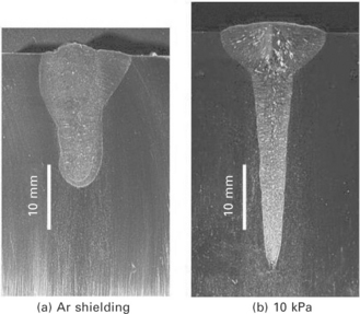
1.12 Cross-sectional photos of laser welds in Type 304 steel produced with 10 kW fiber laser at 0.1 m/min in Ar shielding gas at 1 atm (a) and under low vacuum of 10 kPa (b).
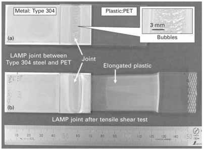
1.13 Laser lap joints of 3 mm thick Type 304 steel plate and 2 mm thick PET plastic sheet before and after tensile shear test, showing that bubbles are formed in melted zone in PET during joining and that elongation of PET base plastic occurs during testing.
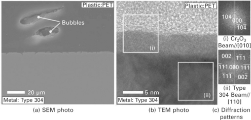
1.14 SEM and TEM photos of cross sections near joint interface between Type 304 steel plate and PET plastic sheet, and diffraction patterns and analyzed results of gray and dark parts, showing Cr2O3 oxide and Type 304 steel, respectively.
In-process monitoring, on-line sensing or adaptive control system during laser welding is required to produce a sound high-quality laser weld.3,4 Reflection of a laser beam and heat radiation from a laser irradiated part and a molten pool are important candidates for monitoring signals. 9,10 The latter is also used for feedback or adaptive control. 10 Direct observation of phenomena during laser welding is also important in terms of understanding of formation mechanisms of welding defects. Recently, great advances have been made in this research and the systems have been employed in practical applications.
1.6 References
1. Katayama, S. Laser welding. Ferrum (Bulletin of the Iron and Steel Institute of Japan). 2012; 17(1):18–29. [(in Japanese)].
2. Katayama, S. Laser welding of aluminum alloys. Keikinzoku (Journal of Japan Institute of Light Metals). 2012; 62(2):75–83. [(in Japanese)].
3. Katayama, S. New development in laser welding. In: Ahmed N., ed. New Developments in Advanced Welding. Cambridge: Woodhead Publishing; 2005:158–197.
4. Katayama, S. Understanding and improving process control in pulsed and continuous wave laser welding. In: Lawrence J., Pou J., Low D. K. Y., eds. Advances in Laser Materials Processing – Technology, Research and Applications. Cambridge: Woodhead Publishing; 2010:181–210.
5. Katayama, S., Abe, Y., Mizutani, M., Kawahito, Y. Development of deep penetration welding technology with high brightness laser under vacuum. Physics Procedia. 2011; 12(1):75–80.
6. Katayama, S. Laser welding of dissimilar materials. The Review of Laser Engineering. 2010; 38(8):594–602. [(in Japanese)].
7. Katayama, S., Kawahito, Y. Laser direct joining of metal and plastic. Scripta Materialia. 2008; 59(12):1247–1250.
8. Katayama, S, Jung, K-W, Kawahito, Y, High power laser cutting of CFRP, and laser direct joining of CFRP to metal. Proc. of 29th ICALEO 2010,. 2010; 103:333–338.
9. Katayama, S., Kawaguchi, S., Mizutani, M., Kawahito, Y., Tarui, T. Welding phenomena and in-process monitoring in high power YAG laser welding of aluminum alloy. J. of Light Metal Welding & Construction. 2008; 46(10):480–490. [(in Japanese)].
10. Kawahito, Y., Katayama, S. In-process monitoring and adaptive control for prevention of through-holes in full-penetration lap welds of aluminum alloy sheets. Journal of Laser Applications. 2006; 18(2):93–100.
The content of this chapter has been reprinted with permission from the article ‘laser welding’ in the McGraw Hill Encyclopedia of Science & Technology, Vol. 9 (2012), pp. 707–714, written by Seiji Katayama. The author would like to express his gratitude to this company.

