Developments in laser microwelding technology
Abstract
The term microwelding, also known as precision welding or microjoining, is somewhat elusive and consensus on a precise definition is probably very difficult to achieve. For this chapter a working definition is suggested, i.e. laser microwelding concerns the joining of parts having a weld bead size < 1 mm and a weld penetration depth of < 1 mm. Laser microwelding is used for joining high value miniature components in a range of industries (i.e., electronics, telecom, automotive and medical). Typical applications include catheters or implants, orthodontic brackets, fibre optic couplings to laser diodes, hermetic seals, watch part components and other photonic fabrication devices. This chapter reviews the basics of laser microwelding, including the laser choice for microwelding, the microwelding process and the quality of microwelds. The chapter also examines applications of microwelding and covers future trends in microwelding technology.
7.1 Introduction
A range of small components are increasingly being used in microelectronics and engineering devices. These miniature parts are made of complex shapes and material combinations which require joining techniques capable of producing good mechanically sound joints. This has increased the interest in the use of lasers for microwelding in a range of applications. The term microwelding, also known as precision welding or microjoining, is somewhat elusive and it is probably very difficult to reach consensus on a precise definition. For this chapter, a working definition is suggested, i.e. laser microwelding concerns the joining of parts having a weld bead size less than 1 mm and a weld penetration depth of less than 1 mm. Apart from the weld bead size and weld depth penetration, other laser microjoining requirements are:
![]() very fine welds (spot sizes could range from approx. 10um up to 100um)
very fine welds (spot sizes could range from approx. 10um up to 100um)
![]() reduced distortion and heat affected zone
reduced distortion and heat affected zone
![]() process reliability and stability (pulse to pulse stability for micro spot welding)
process reliability and stability (pulse to pulse stability for micro spot welding)
![]() high process speed (welding with scanner)
high process speed (welding with scanner)
Laser microwelding is used for joining high value miniature components in a range of industries (i.e., electronics, telecom, automotive and medical industry) (Table 7.1). Typical applications include catheters or implants, orthodontic brackets, fibre optic couplings to laser diodes, hermetic seals, watch part components and other photonic fabrication devices.1–3
Table 7.1
Examples of microwelding applications
| Market sector | Applications |
| Automotive | Air bag assemblies, fuel injectors, lighting assemblies, batteries, ignition controls |
| Medical | Hearing aids, prosthetics, pacemaker and defibrillator implants, implantable radioactive capsules, cochlear implants, surgical tools, ultrasound catheters, orthodontic appliances |
| Electronics | Leadframe assemblies, electrical connectors, relay terminal connections, mobile phone batteries, flexural arms for hard disc drives, mobile phones, stator spacers, fuel and solar cells |
| Other micro-products | Jewellery, razor blades, sensing devices, thermocouples, micro-pumps, ink-jet cartridges, micro-turbines, micro-motors, micro-gears, watch part components |
Compared to conventional microwelding methods (i.e., resistance, flash, arc, TIG, MIG and plasma), laser microwelding offers a number of advantages including:
![]() low heat input: the weld energy is delivered only where it is needed and with exceptional control
low heat input: the weld energy is delivered only where it is needed and with exceptional control
![]() clean welds: in addition to the aesthetic benefits, clean welds result in products that are easier to sterilise or fit into other assemblies
clean welds: in addition to the aesthetic benefits, clean welds result in products that are easier to sterilise or fit into other assemblies
![]() strong welds: lasers provide high strength with a minimum number of welds
strong welds: lasers provide high strength with a minimum number of welds
![]() hermetic welds: unlike soldering or brazing, lasers can provide flawless hermetic welds essential for many micro-applications.
hermetic welds: unlike soldering or brazing, lasers can provide flawless hermetic welds essential for many micro-applications.
Some of the applications outlined in Table 7.1 require joining dissimilar metals such as stainless steel and copper alloys. Applications like electrical connectors and electromechanical components are normally made out of steel and copper-based alloys. The trends of joining dissimilar metals and the miniaturisation of components offer big challenges for welding methods and will be discussed in later sections.
7.2 Laser choices for microwelding
There are a number of laser sources available for laser microwelding applications, i.e. pulsed Nd:YAG, fibre, disk, diode and CO2. The choice of laser will depend on the specifi c aspects of the application such as material type, cycle time, fit-up tolerance, integration requirement and, most importantly, the cost of the laser system. The choice of a laser source for a specifi c application is no longer straightforward and obvious. Laser users are now faced with additional questions of laser beam quality and brightness. The main advantage of high beam quality is that the laser beam can be transported via a small diameter optical fibre, which translates to a small spot size at the workpiece.
7.2.1 Beam quality
For the majority of microwelding applications, it is necessary to have a laser with good beam quality to produce a small spot size at the workpiece. A combination of good beam quality and small spot size offers a number of advantages during microwelding including:
The quality of a laser beam can be calculated by the beam parameter product (BPP),4 which is defined as the product of a laser beam’s divergence angle (half-angle) and the radius of the beam at its narrowest point (the beam waist):
where ω0 and θ denote the beam waste radius and the laser beam’s divergence angle, respectively (Fig. 7.1) and the BPP quantifies how well the laser beam can be focused on to a small spot. A Gaussian beam has the lowest possible BPP, λ/π, where λ is the wavelength of the light.
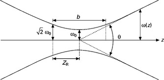
7.1 Gaussian beam width ω (z) as a function of the axial distance z. ω0: beam waist; b: depth of focus; zR: Rayleigh range; θ: total angular spread.
The ratio of the BPP of an actual beam to that of an ideal Gaussian beam at the same wavelength is denoted M2
The beam quality M2 parameter is a wavelength-independent measure of beam quality. Figure 7.2 shows beam quality data for commercial and laboratory lasers.4
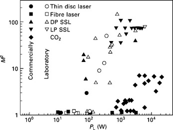
7.2 Beam quality (M2) vs. laser output power (W) for selected laser sources used for laser material processing.4
For a number of years, low power (up to 300 W) lamp-pumped pulsed Nd:YAG lasers with an adequate beam quality (M2 = 15–20) have been the laser of choice for a number of microwelding applications. At a wavelength of around 1 μm, the focusing optics are smaller and simpler to enable smaller spot sizes than equivalent CO2 lasers. As these devices are getting smaller and smaller, it is very important to have laser sources that have good beam quality to produce a small spot size and produce a very stable output for a consistent process.
The need for more efficient, compact and high beam quality lasers for very fine microwelding has fuelled the rapid growth in developing fibre lasers. The following sections highlight the advantages and disadvantages for both pulsed lamp-pumped and fibre lasers for microwelding applications.
7.2.2 Laser structure
Figure 7.3 shows the basic components comprising a laser. The gain medium is capable of producing light when the excitation energy is applied to it. The front and rear mirrors define the resonator, which ensures the light reflects back and forth through the gain medium, thus gaining in intensity and reducing in angular spread. The fraction of the light which passes through the partially transmitting front mirror becomes the useful laser beam.
For a CO2 laser, the gain medium is a mixture of gases (mainly helium, nitrogen and carbon dioxide) and the excitation energy comes from the electrical discharge through the gas. The laser beam wavelength is 10.6 μm. For a solid state laser, the gain medium is typically a rod of YAG (yttrium aluminium garnate) doped with about 1% Nd (neodymium) atoms, and the excitation energy is provided by the broadband light from a pulsed flashlamp of a continuous arc lamp. The laser beam wavelength is 1.064 μm.
For a fibre laser, the gain medium is an ytterbium-doped glass fibre, with the excitation energy being provided by laser diodes, operating around 950 nm, coupled by various schemes into the core of the doped fibre. The laser beam wavelength is typically in the range 1.07 μm to 1.09 μm and the physical dimensions of the gain medium for the fibre laser are very different from other laser types. A Nd:YAG rod might be 200 mm, a CO2 discharge around 2 m, but the gain fibre in a fibre laser will be tens of metres long. The reflectors used in the fibre laser are physically very different from traditional lasers. Typically the mirror will be formed from a dielectric coating on substrate, which will be transmissive at the laser wavelength for the output coupler. For the fibre laser, Bragg gratings written into the core of a fibre are used. These fibre Bragg gratings (FBGs) consist of periodic refractive index variations. The longitudinal period of the grating determines the wavelength of the reflected light, and the magnitude of the variation controls the reflected percentage.
Nd:YAG laser
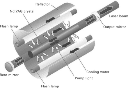
The Nd:YAG laser is a solid-state laser (Fig. 7.4) usually in the shape of a rod, operating at 1.06 μm.5 The active species are neodymium ions present in small concentrations in the YAG crystal. Both continuous wave and pulsed laser outputs can be obtained at an overall efficiency in the 3–5% range. The laser is used in industry because of its efficiency, output power and reliability compared to other solid-state lasers. The crystal is grown using the Czochralski crystal growing technique6 which involves slowly raising a seed Nd:YAG crystal from the molten crystal constituents to extract an Nd:YAG boule. A single boule typically yields several laser rods. The concentration of Nd ions in the boule is carefully controlled and is not greater than about 1.1%. Increasing the Nd doping further in order to increase the laser power can produce unacceptable strain in the crystal which can lead to a dramatic reduction in laser power.
Laser rods are typically 6 mm in diameter and 100 mm in length with the largest commercial size rods being 10 mm in diameter and 200 mm in length. Because of the crystal’s small size, Nd:YAG lasers tend to be much more compact than CO2 lasers. Illustrated in Fig. 7.4 are the main components of a single-rod Nd:YAG laser. Laser action is achieved by optically exciting the crystal by lamps placed in close proximity to it. The lamps have an emission spectrum, which overlaps the absorption bands of the Nd:YAG crystal at 700 nm and 800 nm. In order to couple the maximum amount of lamp light into the rod and extract the maximum laser power from it, the rod and the lamp are enclosed in specially designed and manufactured cavities.
The two most common pump cavity configurations are elliptical and close-coupled. In the case of elliptical cross sections, the rod and the lamp are placed along the two foci, and in the case of close-coupled cavities, the rod and the lamp are placed close together at the axis. The inside surface of the cavity is normally coated with gold in order to maximise the coupling of lamp light into the rod. Some laser manufacturers also manufacture ceramic cavities which produce more uniform pumping of the rod but at the expense of lower efficiency (some 5% lower) compared to that of the gold-coated cavities.
For continuous operation, krypton arc lamps are most widely used, while for pulsed operation high-pressure xenon and krypton flashlamps are used. Lamp lifetime dominates the service requirement of modern Nd:YAG lasers. For arc lamps, the lifetime ranges between 400 and 1,000 hours, while for pulsed lasers it is about 20 to 30 million pulses depending on operating conditions.
As only a fraction of the emitted spectrum is absorbed by the laser crystal, the rest of the emitted light is dissipated as heat in the cavity and has to be removed for efficient laser operation. This is usually achieved by flowing deionised water around the rod and lamp in a closed loop cooling system. The loop is coupled to a heat exchanger for efficient heat removal.
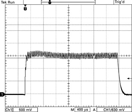
Nd:YAG lasers are characterised by their power output over time, i.e. pulsed, continuous wave and super modulated7, 8 (a feature exclusive to JK continuous wave products).9 Pulsed Nd:YAG lasers employ a power supply designed for delivering high peak powers during the laser pulse and do not have continuous wave (CW) capability. Pulsing implies that the laser’s active medium is excited by a very quick response stimulus. This allows the laser to transmit a burst of energy for a brief length of time (generally in terms of milliseconds). Peak pulse powers for pulsing Nd:YAG lasers can reach values of over 30 times greater than the maximum average power levels. This allows low-to-medium power lasers to achieve enough energy to reach vaporisation temperatures for most materials. The basic laser pulse from the pulsed laser is a rectangular pulse as shown in Fig. 7.5. Often the single sector standard pulse is quite adequate when microwelding standard ferrous alloys without any coating or pulsed Nd:YAG microcutting applications. However, with most welding of reflective or dissimilar materials, pulse shaping has a measurable effect on the quality and consistency.10 Most lasers are rated by their CW output, but pulsed lasers have pulse energy, peak power, pulse width and frequency terminology that must be understood.
Pulse energy
The volume of the melt puddle for each pulse is determined by pulse energy. There is a minimum pulse energy required for weld penetration to a certain weld depth for a given material. Energy per pulse in joules (E) is related to the average power (P) and the pulse frequency (f) by the following:
Peak power
Height of the pulse is the peak power as shown in Fig. 7.6 and this peak power breaks down reflectivity and overcomes thermal diffusivity. High peak power is required for precious metal welding and a range of aluminium alloys. The peak power (Pp) can be calculated by the following:
Pulse frequency and overlap
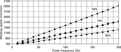
During pulsed Nd:YAG welding, seam welds are produced by a series of spot welds. The pulsing rate of the laser results in faster or slower seam welding as the rate is increased or decreased. To produce hermetic welds, pulse rate (f), spot diameter (d) and the weld speed (v) have to be matched to produce the required percent overlap (%OL). Generally speaking, typical values for hermetic welds are between 70 and 80%OL and for non-hermetic welds between 50 and 60%OL. The percent overlap can be calculated by the following:
Figure 7.7 shows the relationship between welding speed and frequency for three different percentage overlaps.
Fibre laser
The low power fibre lasers are very compact and robust and have an edge over lamp pumped Nd:YAG lasers in terms of beam quality (M2 ≈ 1.1) and wall plug efficiency of approx. 25%.11, 12 Current investigations13, 14 have shown that a single-mode fibre laser is an efficient, reliable and compact solution for microcutting, microwelding and microdrilling. The diode-pumped technology offers low maintenance cycles and high conversion efficiency. Theoretical pump-light conversions of more than 80% are possible15 but typical optical conversion efficiencies for ytterbium double-clad fibre lasers are 60–70%.16 Average power levels up to 500 W are possible with air-cooling. Since the overall efficiency is high, most fibre lasers are powered by standard 110 V/230 V supplies.
In the design of a robust and reliable fibre laser system, a number of other fibre-based components enable the construction of monolithic ‘all-fibre’ laser cavities. The benefits of the all-fibre design have been widely discussed elsewhere,17 with two of the principal advantages being the absence of optical alignment and exposed optical surfaces. Chief amongst these enabling components are the pump combiner and Bragg grating reflector. Figure 7.8 shows a schematic of such a fibre laser cavity design. The output fibre has a single-mode core with a diameter of less than 10 microns which ensures a high beam quality output. This architecture is designed to be capable of producing output powers of up to 500 W with a 100,000 hour diode ensemble lifetime in a water-cooled heatsink configuration and up to 120 W using forced air-cooling at ambient air temperatures of up to 35 °C with the same level of diode reliability.
Central to the performance and reliability of the fibre laser system are the pump laser diodes. In the last ten years, multimode diode pump sources emitting many watts of output power in the 900–980 nm wavelength range have become commercially available. Some of these sources have extremely high levels of reliability, with mean time to failure of greater than 500,000 hours under normal operating conditions. By incorporating a suitable level of redundancy, ensembles of such pump sources having a mean time before failure (MTBF) of greater than 100,000 hours can be used to construct fibre lasers emitting several hundred watts of output power.
The advantages of the fibre laser for industrial applications can be summarised as follows:
Existing advantages of fibre lasers:
![]() High stability of laser output leading to consistency of processing
High stability of laser output leading to consistency of processing
![]() Generally longer warranty than standard lasers
Generally longer warranty than standard lasers
![]() Option of air-cooled or water-cooled up to a few hundred watts output power.
Option of air-cooled or water-cooled up to a few hundred watts output power.
Advantages of emerging industrial fibre lasers:
![]() Integrated damage protection against backreflection issues
Integrated damage protection against backreflection issues
![]() Control software offering full functionality and ability to be integrated into system level controllers
Control software offering full functionality and ability to be integrated into system level controllers
![]() Fault diagnostics for improved warning or alarm identification
Fault diagnostics for improved warning or alarm identification
![]() End-of-life warning for tracking diode lifetimes
End-of-life warning for tracking diode lifetimes
![]() Reliable, stable and linear power monitor integrated to laser
Reliable, stable and linear power monitor integrated to laser
![]() Single sourcing for laser and process tools (cutting head, welding head or galvanometer based scanners)
Single sourcing for laser and process tools (cutting head, welding head or galvanometer based scanners)
![]() Ability to increase processing performance of reflective materials through periodic enhancements to laser peak power.
Ability to increase processing performance of reflective materials through periodic enhancements to laser peak power.
7.2.3 Beam delivery
From the laser microwelding point of view, the laser by itself is very much ineffectual. The laser must be used in conjunction with several different items of optical and mechanical equipment, which need to be integrated into a functional unit, in order to be able to weld materials. It comprises three key elements:
![]() laser source (Nd:YAG or fibre laser)
laser source (Nd:YAG or fibre laser)
![]() beam delivery and focusing optics (fibre delivered)
beam delivery and focusing optics (fibre delivered)
![]() multi-axis, numerically controlled motion system or scanning head.
multi-axis, numerically controlled motion system or scanning head.
Fibre delivery
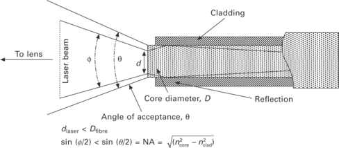
The delivery fibres used with 1.06 μm wavelength industrial lasers are of the ‘step index’ design. This means that they have a core with a high refractive index surrounded by a cladding with a lower refractive index (Fig. 7.9). Transmission of light occurs by total internal reflection at the core/cladding interface due to the refractive index difference between the core and the cladding. A property of these fibres is that the exiting beam has a relatively homogeneous intensity distribution over its diameter. Depending on the power of the laser, the core diameters range in size from 100 to 600 μm for pulsed Nd:YAG lasers and from 10 to 20 μm for single-mode fibre lasers. The fibres are manufactured from high purity fused silica and possess minimal loss at the laser wavelength.
To launch a laser beam into a fibre, so that it experiences a minimal transmission loss as it propagates along it, requires that the diameter of the focused spot on the fibre face be smaller than or equal to the fibre core diameter. The focused spot size in commercial systems is normally 80–90% of the core diameter, which allows for easier adjustment of the fibre and any variation in the spot diameter due to laser parameters.18 In addition, the divergence of the input laser beam must be less than the acceptance angle of the fibre defined by its numerical aperture, NA.
Delivery of the output beam to the workpiece is an important issue. A fibre laser beam delivery system must protect the fibre end-face from damage due to contamination or back-reflected light from the workpiece. Furthermore, to take advantage of the high beam quality in microwelding applications, high quality optics and ‘through-the-lens’ viewing are advantageous. GSI Group Laser Division manufactures fibre end-terminations, process and scanning heads.19
Figure 7.10 shows a schematic of a fibre termination (Luminator™ technology) designed for high-power YAG laser fibre beam delivery of the JK laser products. This patented technology makes use of a fibre mounting scheme and an angled capillary that is robust against back reflection. GSI are using a variation on this existing design for fibre laser beam delivery. By applying the patented Luminator™ technology to the beam delivery fibre on the GSI Group fibre lasers, an integrated protection system against back reflection issues has been provided that protects the fibre laser at a number of levels.
As the effective mode area at the end of the delivery fibre is very small for single-mode beams, so the power density on the fibre ends is extremely high, meaning that they can be easily damaged if contamination is present, especially in the presence of back-reflected light. By shaping the fibre end, so that the beam is allowed to expand in diameter before it exits the silica material of the delivery fibre, the occurrence of this damage mechanism can be greatly reduced.
Scanning heads
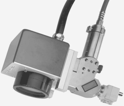
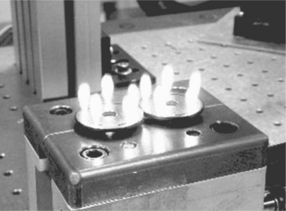
Laser microwelding with a scanning head provides significant advantages over the conventional process tool-based systems. Areas from fractions of square meters to a few square meters can be scanned depending on whether the galvanometer mirrors are in a fixed or movable arrangement (Table 7.2). This can be achieved at rates of many metres per millisecond, which significantly reduces processing cycle time and increases the productivity. In most welding applications the average welding time is 20–50% of the cycle time, which is relatively short compared to the positioning and loading time of the system. By reducing the non-productive times during the manufacturing process with a scanning head, the welding time can be increased by up to 90% or more. Additionally, the shape of the weld can be programmed in a variety of geometrical shapes and figures such as circle, sine wave, open circle and spiral, giving laser welding further structural advantage over conventional spot and MIG welding. As a leader in both the scanner and laser fields, GSI19 has developed its own scanner and integrated software solution to enable laser-based scanner delivered processing. The system has been designed specifically for laser processing applications rather than the more traditional marking applications for which scan heads are predominantly used. The software application has been seamlessly integrated into its industry-leading LaserViewSE™ laser software.19 The end result is a single user application that allows the operator to manage all laser and scan head programming functions. Figure 7.11 shows a scanning head fitted with delivery fibre from the laser and Fig. 7.12 shows spot welds made with the scanning head system.
Laser performance
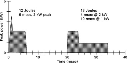
An area where there is a significant difference between lamp-pumped YAG and fibre laser performance is pulsed operation. Lamp-pumped lasers are capable of producing long, multi-ms pulses with peak powers many times the rated average power of the laser, provided that the duty cycle is sufficiently low. This ability stems from the flash-lamp itself, which is often more constrained by the maximum average thermal load than the peak power output. Pulsed Nd:YAG lasers employ a power supply designed for delivering high peak powers during the laser pulse and do not have CW capabilities. These lasers are very good for welding highly reflective materials. High peak power overcomes the thermal diffusivity and reflectivity of precious metals, copper and aluminium alloys. Some materials, i.e. high carbon steels, casting alloys, and a range of aluminium alloys, are difficult to weld. These materials tend to either crack or produce welds with pores or other defects. It may be possible to produce defect-free welds in these materials by changing the laser pulse shape.20 The basic laser pulse from a pulsed laser is a rectangular pulse which is adequate for microwelding most ferrous materials without any coating or plating. For crack-sensitive alloys, welding of dissimilar materials or materials with coatings, a metallurgical, or sometimes known as ramp-down, temporal pulse shape is used.20
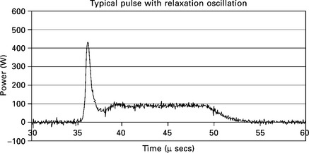
By contrast, while the semiconductor laser diodes used to pump a fibre laser can be on-off modulated over a wide frequency range as shown in Fig. 7.13 (from DC to tens of kHz in most industrial applications), they cannot typically be over-driven for long periods (multi-ms), in the same way as a flash-lamp, without reducing the lifetime of the device to an unacceptable level.
7.2.4 Beam profiles
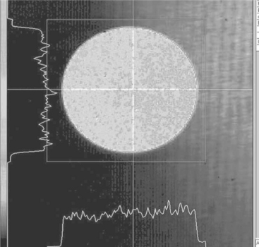
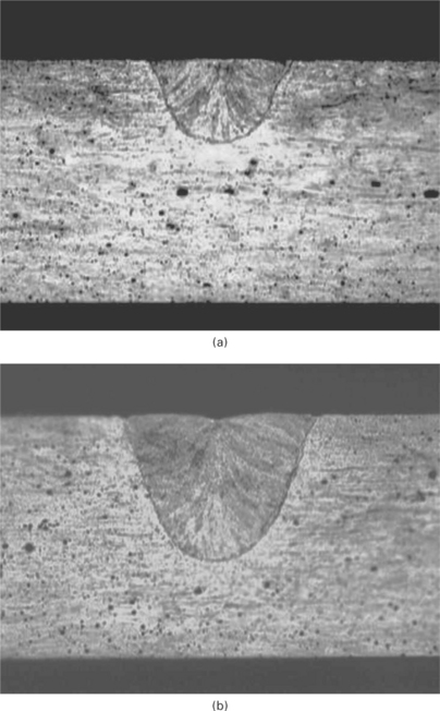
Apart from different temporal pulse shapes of both lasers, another factor to consider when choosing a laser for microwelding is the beam profile of the lasers. The beam profile of the laser can affect the welding performance, i.e. weld penetration depth, weld profile and weld quality. A top hat beam profile as for lamp-pumped pulsed Nd:YAG lasers (Fig. 7.14), for example, is more forgiving since the power and energy are evenly distributed across the weld zone. Top hat energy distribution is achieved when the laser beam is delivered to the workpiece via a fibre optic cable. Increasing the pulse energy increases the weld depth (Fig. 7.15). Vaporisation does not occur if the power/energy density remains below the vaporisation point.
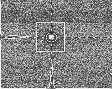
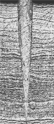
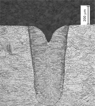
The beam profile from a single-mode fibre laser is Gaussian in profile (Fig. 7.16). This produces very deep and narrow welds (Fig. 7.17). For overlap joint welds, this weld shape is not so good in terms of mechanical properties because the interface is very small compared to the top hat beam profile. However, it is possible to have a low power fibre laser 100–500 W with a flat top beam profile (Fig. 7.18). This leads to a lower beam quality by introducing extra fibre modes and the delivery fibre is of large core diameter, i.e. 100 μm compared to 10–20 μm diameter fibre for the Gaussian beam profile. Both of these beam profiles can provide advantages during microwelding.
7.2.5 Nd:YAG versus fibre
Considering the differences in beam quality and pulsed performance between the two types of laser, there are different operating regimes for the two types of laser. The lamp-pumped YAG laser is characterised by long high-energy pulses but poorer beam quality, and the fibre laser is associated with high repetition rate, on-off type modulation, single-mode beam quality but low pulse energy. From the perspective of microwelding applications, both of these regimes have their advantages and a few of the application examples are highlighted in Section 7.5.
7.3 Laser microwelding process
7.3.1 Welding modes
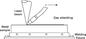
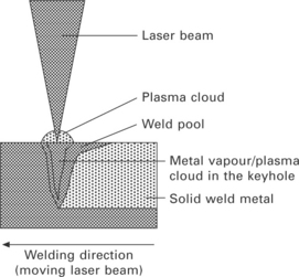
The heat transfer and molten metal flow experienced during laser microwelding can significantly influence the weld pool geometry, solidification structure,21, 22 and defect formation.23 Laser beam microwelding is a process that melts and joins metals by heating with a focused laser beam. Figure 7.19 shows the schematic setup for laser welding. The focused laser beam is made to melt the workpiece or joint at given laser power and welding speed. A shielding gas, usually an inert gas, is supplied either coaxially or by a pipe to protect the molten weld pool from oxidation. The main features of laser microwelding, which make it an attractive alternative compared to other fusion microwelding processes (i.e. resistance microwelding or arc microwelding), are:
![]() precise narrow and deep welds can be produced with high metallurgical quality
precise narrow and deep welds can be produced with high metallurgical quality
![]() small heat affected zone which reduces metallurgical damage and also allows welds to be made close to heat-sensitive components
small heat affected zone which reduces metallurgical damage and also allows welds to be made close to heat-sensitive components
![]() the low heat input into the material obviating the need for complex jigging and allowing distortion-free welding of thick to thin sections
the low heat input into the material obviating the need for complex jigging and allowing distortion-free welding of thick to thin sections
![]() high process speed (welding speeds in excess of 10 m/min can be achieved with materials of thickness about 1 mm)
high process speed (welding speeds in excess of 10 m/min can be achieved with materials of thickness about 1 mm)
![]() flexibility allowing one laser to be shared amongst a number of workstations
flexibility allowing one laser to be shared amongst a number of workstations
![]() post-weld treatment is not normally required
post-weld treatment is not normally required
![]() welds can be performed in difficult geometries and dissimilar material thicknesses.
welds can be performed in difficult geometries and dissimilar material thicknesses.
Laser microwelding of metals is classified into two welding modes i.e. thermal conduction and keyhole or sometimes known as deep penetration welding.24, 25 Both the laser beam power and the focused spot size with respect to the workpiece will govern the welding modes.
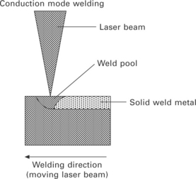
Conduction limited welding (Fig. 7.20) occurs when the laser beam is out of focus and power density is insufficient to cause boiling at the given welding speed. In this welding mode, overlapping spots from a pulsed laser or the beam from a continuous laser is absorbed by the surface of the material and the volume below the surface is heated by thermal conduction producing a semi-circular cross section. The minimum laser power needed to melt the material’s surface can be evaluated by a simple equation.26 When a stationary Gaussian beam interacts with material surface, the temperature at the centre of the heat source T(t) is given by:27
where d is focused laser spot diameter, W is the laser power, A is the absorptivity of the surface, K is the thermal conductivity and α is the thermal diffusivity. Thus the minimum laser power needed to melt a metal of melting temperature Tm is given by:
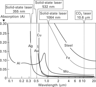
One of the most important parameters influencing the effects of laser–material interactions is the absorptivity of the material for laser radiation and the absorptivity of the material is greatly influenced by the wavelengths and temperature.28 When the laser beam strikes the target material, part of the energy is reflected, the rest is absorbed, and the absorbed energy heats up the target material. The absorptivity is strongly dependent on the material being irradiated and on the laser wavelength. Figure 7.21 shows the absorptivity of some common metals which are routinely used in a range of microwelding applications with different laser wavelengths.28 Figure 7.2226 shows the minimum laser power needed with a given focused spot size to melt common microwelding metals with Nd:YAG wavelength (1.06 μm). It can be seen that silver is the most difficult material for conduction mode welding, requiring almost 900 W to melt. Aluminium-based alloys, steels and nickel are the easiest to weld. Copper is also difficult for conduction mode laser welding because it requires approximately 300 W to melt. Sometimes copper-based alloys are nickel plated to enhance laser absorption and reduce the laser power needed to weld this material.
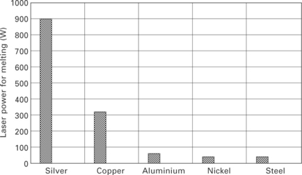
7.22 Minimum laser power needed to melt different metals with pulsed Nd:YAG laser.26
In keyhole or deep penetration welding (Fig. 7.23), the metal surface is heated by a focused laser beam (increased power density) to a temperature where the surface evaporation creates a recoil force sufficient to depress the molten surface into a cavity or a small keyhole. The keyhole grows in depth because of increased coupling of radiation into the workpiece, through multiple reflections of the laser beam off the keyhole walls, and material vaporisation.25, 29, 30 The balance between the hydrostatic forces of the liquid metal surrounding the keyhole governs its existence and the pressure of vaporised and ionised material or plasma within it.
Figure 7.24 shows the transition in the weld bead shape and the weld penetration by changing the power density at the workpiece. The welds were made in stainless steel with a 400 W single-mode fibre laser.31 The micrographs show that as the power density increases, the welding mode changes from conduction to keyhole. During these tests the welding speed was kept constant at 9 m/min.
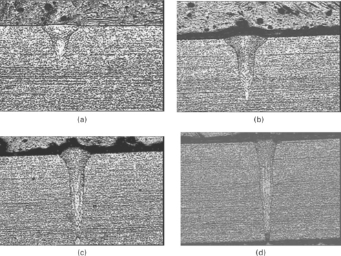
7.24 Welds made with 400 W (JK400FL) single-mode fibre laser; 304SS, 9 m/min, argon shield gas: (a) 4.98 MW/cm2; (b) 5.98 MW/ cm2; (c) 6.98 MW/cm2; (d) 7.98 MW/cm2.31
7.3.2 Welding joints
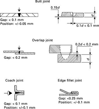
When considering laser microwelding, the design of the joint and possibly the fabrication method of the whole product should be assessed in order to gain the maximum advantage from the process. Laser microwelding requires high tolerances in gap control and joint positioning (Fig. 7.25). For macrowelding, filler material can be used to widen the tolerance field, but in practice this is not very common because of the associated cost related with the process and also reduction in the weld speed. Laser microwelding is usually performed without any filler metals so gaps must be filled with metal from the adjacent area and bridging a gap requires extra laser energy. Generally, a gap no more than 10% of the thickness of the thinnest component is allowed. This can be relaxed for thicker materials greater than 1 or 2 mm but might need to be reduced to 5% or lower for materials less than 0.2 mm. Gap problems show themselves as very concave weld beads or failure to bridge the gap between parts. It is also much more difficult to start a laser weld in a large-gap area compared to seam welds through a short section of high-gap area where bridging can sometimes be maintained. In addition to the suitable preparation and alignment of the joint faces, they should be free from contaminants such as grease, paint, dirt and oxide scales. Residue from chemical degreasing and cleaning agents should be carefully removed, since weld spatter and porosity (see below) can result if these substances are present on the workpiece.
7.3.3 Materials
The metallurgy of laser welding is not much different from other conventional welding techniques, but there are two very important features which make laser microwelding very challenging and the engineer/designer must be aware of these before designing the component and deciding on the material type. The first point to note is that laser welding is almost always an autogenous process, which means that no metal is added during the welding process. This was discussed previously in the consideration of fit-up tolerances. The second special feature of laser welding is the relatively rapid cooling rate of the solidifying metal, which places some special constraints on a few metal choices.
When microwelding microwave packages, a designer requires a lightweight, corrosion-resistant, heat-dissipating, robust, and cheap material. Aluminium is usually the first choice. Aerospace packages for microwave circuits, sensor mounts, or small-ordinance initiators are the most common examples of aluminium components that need to be laser welded. Laser welding with penetrations up to 1.5 mm are common in these applications and 6061-T6 aluminium alloy (Al-Mg-Si) is the material of choice because of economics, rigidity and ease of machining. However, the material cannot be successfully laser welded to itself, because the partially solidified melt zone cannot withstand the stress of shrinkage upon solidifying, and cracks are formed, known as solidification cracking or hot cracking. Hot cracking is the cause of almost all cracking in aluminium weldments. Hot cracking is a high-temperature cracking mechanism and is mainly a function of how metal alloy systems solidify. This cracking mechanism is also known as hot shortness, hot Assuring, solidification cracking and liquation cracking.
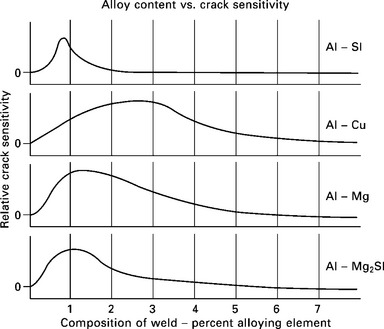
Figure 7.2632 shows the aluminium crack sensitivity curves and is a helpful tool in understanding why certain aluminium welds crack. The crack sensitivity curves show that with the addition of small amounts of alloying elements, the crack sensitivity becomes more severe, reaches a maximum, and then falls off to relatively low levels. After studying the crack sensitivity curves, it is easy to recognise that most of the aluminium-based alloys are considered unweldable autogenously (without filler alloy addition). The solution to this problem is to improve the ductility of the weld metal by using aluminium with high silicon content, such as alloy 4047 (Al-12% Si). This alloy is very ductile as a solid and difficult to machine into complex shapes. Therefore, 6061 is usually employed as the package component with intricate features, and 4047 is used as a simple lid that is relatively thin (typically less than 1 mm). The only aluminium alloys that can be welded with low heat input and without the use of 4047 filler are the 1000 and 1100 alloys. These commercially-pure aluminium alloys have the metallurgical characteristics to avoid hot cracking, but their poor mechanical and machining properties usually prohibit use in most applications.
Kovar (Fe-29% Ni, 17% Co) is another material which is often chosen for microwelding because its thermal expansion coefficient matches that of other package constituents such as glass-to-metal seals. Plated Kovar offers good corrosion resistance and can be machined and drawn relatively easily. Kovar is denser and heavier than aluminium, but it presents few metallurgical problems compared to those of aluminium. In addition, it provides the benefit of a low coefficient of thermal expansion. Usually welded to itself, Kovar welds with ease up to 2 mm penetration. It is important to consider plating constituents when specifying Kovar package components.
Stainless steel with its excellent corrosion resistance and good metallurgical characteristics is used in a number of microwelding applications. Stainless steel is slightly more difficult to machine, and is heavier and more expensive than aluminium. Some aerospace packages employ stainless steel, but the majority of uses seem to be in the military, the medical field or in automotive airbag systems. The various types of stainless steel are identified, and guidance given on welding processes and techniques that can be employed in fabricating stainless steel components without impairing the corrosion, oxidation and mechanical properties of the material or introducing defects into the weld. The unique properties of stainless steels are derived from the addition of alloying elements, principally chromium and nickel, to steel. Typically, more than 12 or 13% chromium is required to produce a stainless iron.
Austenitic stainless steels
These steels are usually referred to as the 300 series and are generally suitable for laser microwelding. Slightly higher weld penetration depths or increased weld speeds can be achieved when compared with low carbon steels (Fig. 7.27)33 due to the lower thermal conductivity of most stainless steel grades. The high speeds of laser welding are also an advantage in reducing susceptibility to corrosion caused by precipitation of chromium carbides at the grain boundaries that can occur with high heat input welding processes. In addition, laser welding of these grades results in less thermal distortion and residual stresses compared with conventional welding techniques, especially as these steels have 50% greater thermal expansion than plain carbon steels. The use of free-machining grades should be avoided because these steels contain high sulphur and high phosphorous that can lead to hot cracking. These elements segregate to the weld centreline, causing a brittle zone that cracks under the stress of solidification (hot cracking).
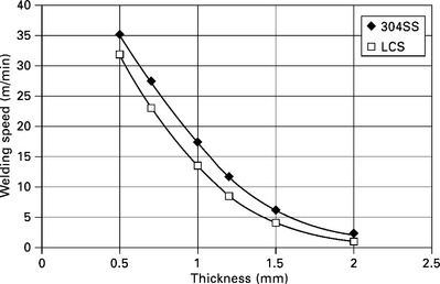
7.27 Welding performance of 304 stainless steel and low carbon steel. Welds made with 400 W single-mode fibre laser (JK400L), spot size 30 μm.33
Ferritic and martensitic stainless steels
These 400 series steels do not possess the good all-round weldability of the austenitic grades. Laser welding of the ferritic grades in some cases impairs joint toughness and corrosion resistance. The reduction in toughness is due in part to the formation of coarse grains in the heat-affected zone, and martensite formation, which occurs in the higher carbon grades. The heat-affected zone may have a higher hardness due to the fast cooling rate. Pre-heating can reduce martensite formation in 400 series alloys. Some 400 series alloys can be welded to 300 series alloys with good results, but again, results can vary from batch to batch, or with variations in heat input.
Titanium and its alloys is another material used extensively in microwelding applications, especially in the medical industry, i.e. for pacemakers and pacemaker battery packages. Commercially-pure titanium and Ti-6Al-4 V weld extremely well, but nitrogen cannot be used as shielding gas because of the formation of titanium nitride. Argon or helium must be used to prevent oxidation.
Pure copper and its alloys are used mainly in microelectronic applications. Pure copper has good metallurgy for welding, but it is highly reflective to Nd:YAG laser energy and has high thermal conductivity, therefore making it difficult to achieve weld penetrations greater than 0.5 mm. The reflectivity of pure copper can be overcome by plating it with electroless nickel before welding. Beryllium copper (BeCu) has better weldability and can produce very good welds to pure copper.
Copper-tungsten is very heavy, but has very good heat conductivity, as well as a thermal expansion close to that of many electrical components. Copper-tungsten and copper-nickel alloys weld well. Brass alloys are not good candidates because of their zinc content. Zinc vaporises near the melting temperature of other metals, and vapour expansion tends to expel metal out of the weld pool. The little molten metal remaining solidifies, trapping the gas pockets in the joint, creating undercutting and porosity.
Both silver and gold can be laser welded but with penetration limited to less than 0.5 mm because of high reflectivity and thermal conductivity. These metals are used for special applications in aerospace, electronics and military ordnance, where corrosion resistance and electrical conductivity are paramount.
7.3.4 Microwelding of dissimilar materials
Many applications in various industrial sectors, i.e. electronics, medical, consumer goods, automotive applications, etc., require joining of dissimilar metals. The trends of joining dissimilar metals of components are creating big challenges for welding methods. The weldability of dissimilar metals depends on many different factors. The physical properties have a big influence on the amount of coupled-in energy and the heat transfer.34 In principle, a laser can also weld any material that can be joined by conventional processes. Illustrated in Table 7.3 is the weldability of metal pairs. In the welding of dissimilar metals, good solid solubility is essential for sound joint properties. This is achieved only with metals having compatible melting temperature ranges. If the melting temperature of one material is near the vaporisation temperature of the other, poor weldability is obtained and often involves the formation of brittle intermetallics. When joining dissimilar materials, there may be certain advantages in using laser welding even though brittle intermetallics may tend to form. Since the weld itself is narrow, the volume of intermetallics may also be reduced to acceptable limits. Again, it may be possible to offset the beam in one direction or the other, thus allowing some control over composition of the resulting alloy. Although it may be possible to produce sound joints by these methods on a laboratory scale, it is more difficult to achieve similar control under production conditions. Mixing the molten metal in a laser weld seldom produces a chemically homogeneous fused zone between the two dissimilar materials. Although the average chemical composition of the weld may be acceptable, local heterogeneity can be responsible for the presence of brittle zones. It will also be apparent that minor variations in the beam position can significantly influence the relative proportions of the two main constituents in the weld zone.
Table 7.3
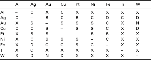
Al: aluminium; Ag: silver; Au: gold; Cu: copper; Pt: platinum; Ni: nickel; Fe: iron; Ti: titanium; W: tungsten
C: complex structures may exist; X: intermetallic compounds formed, undesirable combination; S: solid solubility exists in all alloy combinations; D: insufficient data for proper evaluation; N: no data available
To date most microwelding of dissimilar metals has been carried out with pulsed lamp Nd:YAG lasers.35, 36 Lamp-pumped lasers are capable of producing long, multi-ms pulses with peak powers many times the rated average power of the laser, provided that the duty cycle is sufficiently low. This ability stems from the flash-lamp itself, which is often more constrained by the maximum average thermal load than the peak power output. High peak powers of pulsed lamp pumped Nd:YAG lasers coupled with pulse shaping make these lasers ideal for welding dissimilar materials. The shaping of pulses is of great importance since the temperature has to be controlled in the region where the two molten phases are mixed. Weld depth that is too deep – which can lead to defective joints – and also insufficient weld depths can be avoided by adjusting the high starting power and the correct decreasing power to the joint geometry and the material properties of the pulse shape. Figure 7.28 shows examples of dissimilar material welds made with a lamp pumped Nd:YAG laser. These welds were made with a ramp down pulse shape (Fig. 7.29).
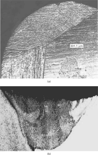
7.28 Examples of dissimilar weld joints; (a) Kovar to stainless steel, (b) 304 stainless steel and bronze. These welds were made with 125 W pulsed Nd:YAG laser (JK125); spot size 60 μm.
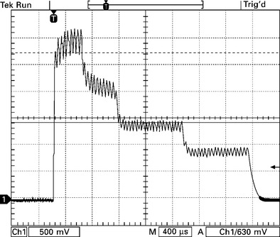
7.29 Example of ramp down temporal laser pulse shape used mainly for welding dissimilar or crack-sensitive materials.
Compared to conventional lamp pumped Nd:YAG lasers, fibre lasers offer a number of advantages when microwelding dissimilar materials. The big advantage of these new laser sources is the beam quality or focusability. Focusability is understood as the ability to achieve a small focus diameter with a given optical element.37 The small focus diameter of the fibre lasers offers a number of advantages during laser microwelding, i.e.
7.3.5 Plating and coatings
The majority of the materials used in microwelding applications are either plated or coated to improve corrosion resistance, solderability, or for better absorption of the laser energy. Nickel and gold are the most common plating choices. Nickel is used alone, and it is almost always used as under-plating for gold or tin. These metals are plated on top of the nickel, because they do not plate well directly to other base metals. Nickel can be plated by an electrolytic or electroless process. Ferrous alloys such as Kovar and stainless steel must be plated with electrolytic nickel. Electroless nickel plating contains phosphorous, which produces intermetallics within the weld that cause porosity and cracking. Gold-plated Kovar packages weld well, as long as there is not under-plating of electroless nickel. Gold-plated mild steel produces weld voids due to intermetallic segregation in the weld. Aluminium and copper can benefit from nickel plating, because the plating has better laser-energy absorbability than the base metals. This technique is not often used with aluminium but is an excellent aid in the welding of copper and its alloys.
Tin and zinc have low melting and vaporisation points, which result in porous welds. These platings should be absent from the weld joint. Even when platings beneficial to laser welding are chosen, there are other plating additives, such as organic brighteners, which can cause problems. Organic brighteners are gaseous when metals are liquid and, as discussed above, they create voids in the weld. Matte finishes with no organic brighteners work best for improving laser welding performance. Platings that only exist on top and not in the joint are often vaporised by the impinging laser beam and will not affect the weld quality.
7.4 Defects and evaluation of microweld joints
7.4.1 Weld defects
Welding defects such as porosity, lack of fusion, spatter, burn through, oxidation and different forms of cracking can occur during laser microwelding either due to material-related problems as outlined in Section 7.3.3 or during the welding process.
Weld cracking
There are a number of cracking mechanisms associated with the welding of metallic alloys. One of the most notorious is hydrogen cracking, also referred to as cold cracking. Hydrogen cracking is often a major concern when welding carbon steels and high strength low alloy steels. However, when welding aluminium alloys, hydrogen cracking cannot occur. Hot cracking is the cause of almost all cracking in aluminium weldments. Hot cracking is a high-temperature cracking mechanism and is mainly a function of how metal alloy systems solidify. This cracking mechanism is also known as hot shortness, hot Assuring, solidification cracking and liquation cracking. The cracking mechanisms that can occur during laser welding can generally be resolved by process parameter optimisation and fixturing. The combination of fixturing and weld configuration often introduces geometry defects that provide location of high stress concentration that can start a crack.
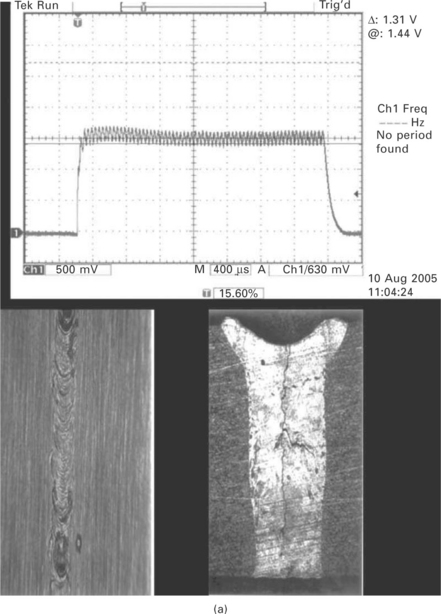
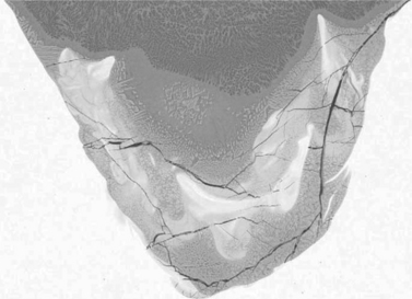
Figure 7.30 shows examples of microweld with excessive cracking and porosity, however, by just changing the temporal pulse shape of the pulsed laser, it is possible to produce defect-free cracks in the same materials.
Undercutting
Undercutting or weld blowout of the microweld is attributed to two main processing parameters. The first mechanism is due to high laser power which results in the expulsion and loss of liquid material from the weld pool (Fig. 7.31). The loss of the material comes from splattering and evaporation.38 However, the loss of the material through splattering is just down to high laser power. A more valid criterion would be the laser power divided by the welding speed, as this governs the heat input and the rapid flow of the energy through the keyhole.39 The other type of undercutting defect is observed when the gap is too big in overlap or butt joint welding (Fig. 7.32). This defect can be prevented by reducing the gap with good fixturing/clamping.
Weld spatter and porosity
Weld spatter is defined as the molten metal droplets that are thrown out of the fusion zone (Fig. 7.33). The formation of the spatter can be controlled by reducing the peak power and reducing the weld temperature. However, changing the peak power settings could also lead to a reduction in the weld penetration.
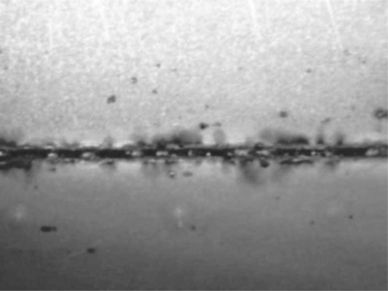
7.33 Combination of high power density at workpiece and low welding speed leading to porosity and spatter during laser welding.
Rapid closing of the keyhole, thus preventing full penetration through the plate, can lead to the formation of porosity (Fig. 7.34). With the rapid cooling usually present with laser welding, pores are left in the weld when the rapidly solidifying pool traps pores before they can float to the surface. However, with pulsed Nd:YAG welding, it is possible to tailor the pulse shape to allow the pores sufficient time to rise to the top. A long cooling segment of the pulse shape is normally utilised to reduce porosity.40
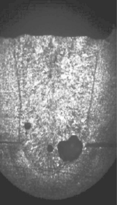
7.34 Rapid closing of the keyhole, thus preventing full penetration through the plate, can lead to the formation of porosity; 304 stainless steel overlap weld joint.
In the majority of cases, some sort of shielding gas is used during laser microwelding. The function of the shielding gas is to protect the weld surface from oxidation and atmospheric contamination. A range of shielding gases can be used (i.e., N2, Ar, He and CO2, etc.). This will depend on the material being welded. The presence of a shielding gas can also cause porosity during laser welding. The gas is entrapped by the turbulent welding pool and keyhole.41
Microwelding of dissimilar materials can introduce a number defects caused by the difference in the mechanical and physical properties. One of the most serious involves the formation of intermetallic compounds in the fusion zone which can lead to microcracking. Figure 7.35 shows a microweld between copper and aluminium showing microcracks in the fusion zone.
7.4.2 Evaluation of welds
Once the microweld has been made, there are a number of different methods available (visual, metallographic sections, mechanical testing and leakage testing) to evaluate the quality of the welds, i.e. cosmetic appearance, porosity, cracking, hermeticity and strength.
The simplest and most widely used method is visual observation of the surface of the weld. This method is very useful for determining if the microwelds are free from spatter and surface oxidation, and for in-depth analysis (i.e. cracking, porosity weld penetration, etc.), metallographic methods are required. This method is very slow but very necessary to evaluate the microwelds, and extreme care should be taken when sectioning very small components. The metallurgical laboratory should be well equipped with the suitable equipment to cut and polish very small parts.
Leak testing is another method which is very common for checking hermeticity of the microwelds. Lithium ion batteries and microwave packages are two of the applications which are tested for leaks. Figure 7.36 shows a typical leak detection jig used for checking welded batteries. Leak tests are performed on the welded samples to check that battery case (can and cap) and electrolyte inlet (ball and cap) are hermetically sealed. The samples are tested with nitrogen gas at 15 kgf/cm2 for 5 minutes in water. The schematic of the leak test is shown in Fig. 7.37. The welds are good, i.e. hermetically sealed, if no bubbles are observed along the length of the weld and around the ball and cap.
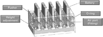
7.36 Leak testing jig mainly used for checking hermeticity of laser-welded lithium ion batteries (courtesy of Hana, South Korea).
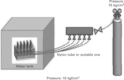
7.37 The schematic of the leak test. The welds are good, i.e. hermetically sealed, if no bubbles are observed along the length of the weld and around the ball and cap.
For tensile strength, small-scale tensile testing machines are used to evaluate the strength of the microwelds. During the pull test, the welded joint is often exposed to a complex stress state, resulting most often in tensile shear of the weld zone.42 During laser microwelding it is important to consider the effect of the weld process on the raw parent material. The strength of the overlap weld joint is governed by power density and the spot size of the laser beam.
The mechanical properties of these joints are governed to an extent by the weld width at the interface. A weld width equal to or greater than the thinnest sheet thickness is a suitable target. Table 7.4 shows the effect of spot weld diameter and the nugget size on the shear strength of the spot welds. These spot welds were made with single-mode 200 W fibre laser in thin foils of stainless steel. At low power the weld had very little strength due to very small nugget size at the interface. As the power increases, the weld diameter also increases, which produces spots welds with good strength due to bigger nugget size.
7.5 Applications of laser microwelding
Laser microwelding plays a very important role in joining microparts for a number of industries, i.e. medical, electronics, automotive and consumer goods, and some applications are listed in Table 7.1.
7.5.1 Examples of laser microwelding applications
Lithium ion batteries for portable applications such as mobile phones and laptops are made in very high volumes and as such need very high throughput on production lines to make manufacture cost effective. Lithium cells are poisoned by water vapour, so a hermetic seal of the cell is critical for long life. Laser welding a lid to the can is fast, reliable, low cost, and easy to automate. Pulsed YAG lasers produce the necessary pulse energy and peak power to produce hermetically sealed welds with the required penetration for the mechanical strength. Galvo-mirrors or translating optics can be used to match the speed of the cells if a weld-on-the-fly application is needed. Figure 7.38 shows an example of a lithium ion battery welded with a JK300HP (300 W average power).
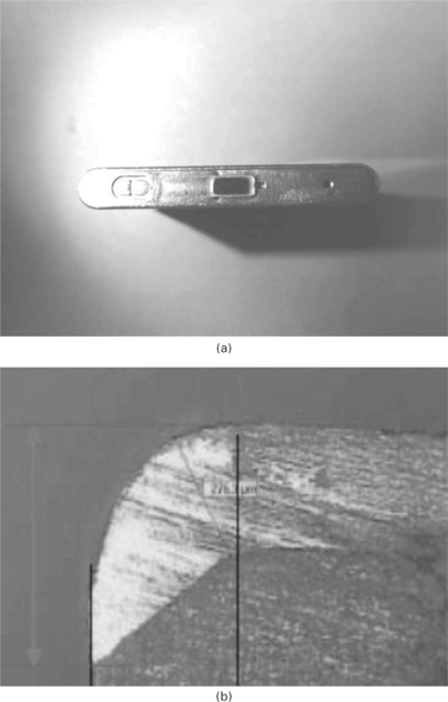
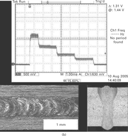
7.38 (a) Lithium ion battery welded with pulsed Nd:YAG laser at 50 mm/sec; weld penetration (b) 350 μm. The battery is made of aluminium alloy (0.2 mm thick case and 1 mm thick cap).
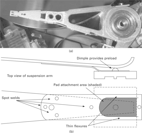
Disk drive flexures (Fig. 7.39) hold the ferrite reader that floats over the spinning magnetic media in a hard drive. The high speeds of positioning and the ultra-close proximity of the ferrite reader mean that this assembly must be accurately assembled from three or four pieces of stainless steel with thicknesses ranging from 20 μm to more than 200 μm. Their design must accommodate resonances, stiffness, and overall component accuracy in three planes. Assembly of these flexures must be highly automated for low-cost, repeatable manufacture.
Lasers have been the only joining solution available for this application since the early 1980s. Their ability to produce discreet energy levels and pulse shapes for each weld location and relative thickness means that each weld is tailored to its target and the welding rate can be over 150 welds/second. Most systems today use galvo-mirrors that direct the laser beam through a flat-field lens onto the part. Ultra-precise fixtures hold the parts together for laser welding and also feed inert gas to the weld area for clean, smooth, oxide-free welds. Any brittle oxide or melt spatter on the surface can flake off and contaminate the drive rendering it useless. For this application both low power Nd:YAG and fibre lasers can be used to produce welds. Figure 7.40 shows spot welds made with both lasers.
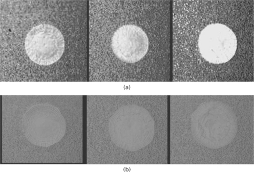
7.40 Laser spot welds, 304 stainless steel (51 + 102 μm); (a) pulsed Nd:YAG laser, (b) single-mode fibre laser.
Medical devices – pacemakers, defibrillator and drug-pump – welding implanted medical devices that incorporate electronics and sensors, require process control and end-product quality that is second to none. These devices must not only function flawlessly, they must have an aesthetic quality that helps with sterilisation and does not irritate the tissue. The welds on these implantable devices must be a hermetic seal very close to heat-sensitive components and since the value of the component before welding is very high, the yield from the welding process must also be high. Pacermakers and defibrillators are electronic devices that are encased in a titanium package that holds the circuitry and battery. Most of the laser welding employed with these units is in the outer case weld. Drug pumps are more complex since at their core they are a mechanical pump and reservoir system along with control electronics and batteries. Laser welding of the different mechanical sub-assemblies and reservoirs means that dozens of laser welds can be part of these systems.
Low-power pulsed YAG lasers (300 W) are the best choice for medical package assembly and sealing. Their high peak powers and low heat input can handle all the different alloys and create a very tolerant process while maintaining deep penetrations. Fibre optic beam delivery is most common for these parts because of the consistent focus spot size and top-hat energy distribution which helps with fillet and butt joints to fill any gaps and get good weld nugget size for maximum yield. It may be also possible to weld some of these medical devices with CW fibre lasers (200 W), but care is needed to optimise the laser parameters because pure CW power may cause distortion of the sensitive parts of the component. Figure 7.41 shows a titanium hearth pacemaker welded with a JK300HP (300 W). The weld penetration is approx. 200–250 μm.
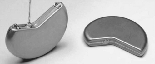
7.41 The seam weld around the cardiac pacemaker demonstrates the precision that can be achieved with a laser process. A laser welding also offers a greater degree of control resulting in stability, excellent repeatability, and consistency. Pacemakers require high integrity hermetic seals at the same time as ensuring well-controlled depth of penetration and low heat input to prevent damage to internal components.
Radioactive isotopes (Fig. 7.42) used for cancer therapy have a rather short half-life and must be produced to order and shipped immediately for implanting into the patient. The capsules or seeds containing radioactive elements are implanted into the body inside or near the cancer itself to produce a much localised radiation treatment. Other radioactive isotopes are used in heart procedures where the radioactivity helps reduce scarring around stents that begin to close the vessel sometime after the stent is inserted. In this case the radioactive material is laser sealed into a capsule and the capsule attached or laser welded to a lead for insertion into the body. It takes several minutes to locally radiate the artery around the stent.
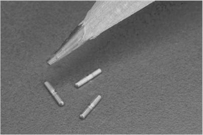
7.42 Laser welded radioactive isotopes. Pulsed YAG lasers are the best choice for capsule and seed assembly and sealing. Their high peak powers and low heat input create a very tolerant process while maintaining consistent shallow weld penetrations (200 μm).
For implantable medical applications, the alloy of choice is titanium which is very easy to weld due to its low thermal conductivity. Its reactivity with oxygen and nitrogen is the only process drawback. Weld shielding with argon is critical for bright silver welds. Pulsed YAG lasers are the best choice for capsule and seed assembly and sealing. Their high peak powers and low heat input create a very tolerant process while maintaining consistent shallow weld penetrations (200 μm).
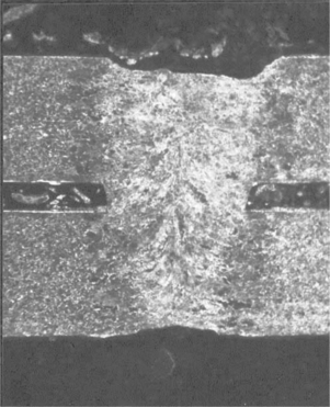
In microwave packages welding (Fig. 7.43), the microwave circuitry is different from many other electronic devices in that the package around the active elements is also part of the microwave circuit. Since most microwave circuits involve expensive radar or communication systems, they require a very high reliability hermetic seal and a high yield. Therefore, their packaging must be robust, hermetically sealed, and capable of being opened and reworked when needed. Laser welding meets these requirements. A laser weld produces a hermetic seal so that no contaminants can reach the circuits and the weld also traps a very high quality inert atmosphere in the package. Laser welding has very low heat input and can be placed very close to polymer seals, glass-to-metal seals, soldered components and electronic circuits.
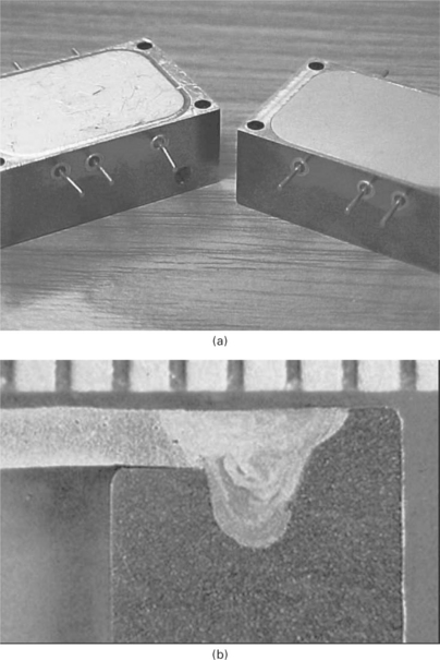
7.43 (a) Laser welding of microwave packages: a laser weld produces a hermetic seal so that no contaminants can reach the circuits and the weld also traps a very high quality inert atmosphere in the package. (b) Weld cross section of drop-in cover shown in (a). The cover is 0.50 mm thick 4047 aluminium alloy and the housing is 6061 aluminium alloy. Weld penetration is 1.20 mm.
For aerospace applications, the alloy of choice for these packages is aluminium. It has the electrical and thermal properties, is easy to machine, and very light weight. 6061-T6 alloy is used for the base of the package and then a 4047 alloy lid is laser welded onto the base with a butt, lap or fillet joint. The 12% silicon-aluminium alloy 4047 can be fusion welded to the 6061 without cracking, creating a strong hermetic seal. For rework, an end mill will machine through the laser weld back to the same level as the original base. Once repaired, another lid can be located on the package and laser welded again. The number of repairs is virtually unlimited. In some instances, a laser weld is required through the lid into dividing labyrinth walls in the base to isolate certain parts of the circuit from others. Some microwave packages can use stainless steel or Kovar components.
7.6 Conclusion and future trends
Laser microwelding is an established technology that is becoming both a necessity and a valuable asset for manufacturing micro components for various industry sectors, and a range of industrial lasers with diffraction-limited spot sizes are available to meet the growing demand.
More and more of the microwelding applications will require joining dissimilar metals with different mechanical and physical properties which creates big challenges for welding. In the future, laser microwelding of dissimilar material combinations will benefit from a deeper understanding of welding methods and materials, so that good quality welds can be produced in a range of material combinations. The weldability data outlined in Table 7.3 need more detailed study in terms of welding technology, as most small-scale laser welds will cool very rapidly giving rise to many welding defects, and the process can violate what the handbook would indicate as a weldable material combination. There is also potential for using lasers to microweld plastics to metals or plastics to ceramics. Metals are strong and ductile, and plastics are light and easily formable, and a laser joining technology for direct bonding a metal and a plastic, called laser-assisted metal and plastic (LAMP) joining, has been developed.43 LAMP joining is performed by melting the plastic near the joint interface and then forming small bubbles in the melted plastic by utilising a simple lap joint. The transmitted laser beam is absorbed to heat the metal surface, and the plastic near the joint can be melted to form bubbles by the heat conducted from the metal. The metal interface near the lap joint is not melted, but the plastic on the metal plate is melted to form small bubbles. The LAMP joining is applicable to bond thermoplastics, especially engineering plastics, to any metal. A strong LAMP joint is characterised by the formation of small bubbles in the plastic near the joint, which should be heated above the decomposition temperature of the plastic. This LAMP joining technology is applicable to many combinations of metals such as steels, titanium and aluminium alloys, and plastics such as PET, polyamide (PA) and polycarbonate (PC). It is also confirmed that LAMP joining is applicable to the joining of dissimilar metals with a plastic intermediate layer sheet in terms of the preventive means of local electric-physical corrosion in the metals.
Lastly, a key future trend in microwelding is a push towards more complete microwelding systems, i.e. good fixturing for good part fit-up, good gas shielding system, good vision system and some sort of in-process monitoring. It is very easy to produce sound welds in the laboratory environment by optimising laser and processing parameters. In production, however, it is not that easy to maintain optimal parameters of output and mode of laser beam, since the focusing optics or the cover glass slides can deteriorate in long-term operation. The weld quality can also be affected by non-laser conditions such as fit-up between the parts, variation in input materials, contamination (oil or dust), focus position and oxidation of the work surface. Thus it will be useful and cost saving to evaluate the weld quality during the welding process by in-process monitoring. The use of a complete microwelding system has the potential to improve the overall weld quality, reduce the cost and improve reliability by removing the human element and inherent variability of the manual process.
7.7 References
1. Olowinsky, A. M., Kramer, T., Durand, F., Laser beam micro welding in watch industry San Jose, CA,. Proc. SPIE – The International Society for Optical Engineering. Photon Processing in Microelectronics and Photonics 2002; 4637:571–580.
2. Witte, R., Herfurth, H. J., Bauer, I., Microjoining of dissimilar materials for optoelectronic and biomedical applications San Jose, CA. Proc. SPIE – The International Society for Optical Engineering. Micromachining and Microfabrication Process Technology VIII 2003; 4979:226–233.
3. Ready J., Farson D., eds. Handbook of Laser Materials Processing. Orlando, FL: Laser Institute of America, 2003.
4. Hugel, H. New solid-state lasers and their application potential. Optics and Lasers in Engineering. 2000; 34:213–229.
5. Koechner, W. Solid-state Laser Engineering, 2nd edn. Berlin: Springer-Verlag; 1988.
6. Dawes, D. G. Growing crystals for solid state lasers. December: Lasers and Optronics; 1987.
7. Naeem, M., Material processing with super-modulation. Proc. ICALEO 2002. Laser Institute of America, Scottsdale, AZ, 2002.
8. Naeem, M., Welding performance of a 2 kW continuous wave supermodulated Nd:YAG laser – increased weld speed, weld penetration and reduced porosity with supermodulated power. Proc. PICALEO 2008. Laser Institute of America, Beijing, China, 2008.
9. Graham, H. Throwing light on materials processing … an addition to laser family. May–June: TWI Bulletin; 2006.
10. Naeem, M., The influence of pulse shaping on laser material processing. Proc. 9th NOLAMP Conference, Nordic Conference on Laser Material Processing. 2003:239–249. [Trondheim, Norway].
11. Norman, S., Zervas, M. N., Appleyard, A., Durkin, M. K., Horley, R., Varnham, M. P., Nilsson, J., Jeong, Y. Latest development of high-power fibre lasers. Fibre Lasers: Technology, Systems, and Applications, San Jose, CA. Proc. SPIE. 2004; 5335:229.
12. Dominic, V., MacCormack, S., Waarts, R., Sanders, S., Bicknese, S., Dohle, R., Wolak, E., Yeh, P. S., Zucker, E. 110 W fibre laser. Electronics Letters. 1999; 35:1158.
13. Naeem, M. Micromachining with a single mode 100 W fibre laser’, Proc. Kyoto Research Park, Kyoto, Japan: LAMP; 2006.
14. Naeem, M., Lewis, S. Pulsed Nd:YAG laser or continuous wave fibre laser for micromachining?. Munich: Proc. WLT-Conference on Lasers in Manufacturing; 2007.
15. Reichel, V., Unger, S., Hagemann, H., Auerbach, M., 8 W highly efficient Yb-doped fibre laser Proc. SPIE. 2000:3889.
16. Nilsson, J., Grudinin, A. B., Turner, P. W. Advanced pulsed and CW high-power fibre laser. CLEO: Proc; 2000.
17. Schoenfelder, A. Fibre lasers address micromachining methods. June: Laser Focus World; 1999.
18. Hunter, B. V., Leong, K. H., Miller, C. B., Golden, J. F., Glesias, R. D., Laverty, P. J., Selecting a high-power fibre-optic laser beam delivery system Section E,. Proc. ICALEO ʼ96. Laser Institute of America, Orlands, FL, 1996:173–182.
19. Lasers, J. K. GSI Company Group, Product Datasheets & Brochures. http://www. jklasers. com/downloads, 2010.
20. Naeem, M., Collins, P., Micro-joining with pulsed Nd:YAG laser Munich. Proc. WLT-Conference on Lasers in Manufacturing. 2005:643–649.
21. Zacharia, T., David, S. A., Vitek, J. M., DebRoy, T. Weld pool development during GTA and laser beam welding of type 304 stainless steel, Part I – Theoretical analysis. Welding Journal. 1989; 68:499s–509s.
22. Zacharia, T., David, S. A., Vitek, J. M., DebRoy, T. Heat transfer during Nd:YAG pulsed laser welding and its effect on solidification structure of austenitc stainless steels. Metallurgical Transactions A. 1989; 20A:957–967.
23. Tomie, M., Abe, N., Yao, X., Arata, Y. 1988, ‘Tandem electron beam welding (Report – VIII)’. Transactions of JWRI. 1988; 17(1):299–303.
24. Arata, Y., Miyamoto, I. Laser welding. Technoctat. 1978; 11(5):33–42.
25. Miyamoto, I., Maruo, H., Arata, Y., Mechanism of bead-transition in laser welding. Int. Conference Welding Research in the 1980s. The High Temperature Society, Osaka, 1980:103–108.
26. Miyamoto, I., Knorovsky, G. A. Laser microwelding. In: Zhou Y., ed. Microjoining and Nanojoining. Cambridge: Woodhead Publishing; 2008:345–417.
27. Pittaway, L. G. The temperature distributions in thin foil and semi-infinite targets bombarded by an electron beam. Brit. J. Appl. Phys.. 1964; 15:967–982.
28. Ready, J. F. Industrial Applications of Lasers. New York: Academic Press; 1978.
29. Deininger, C., Mueller-Borhanian, J., Dausinger, F., Huegel, H., Development of multi-detector systems for processing monitoring of laser beam welding capable for industrial use Proc. Lane. 2004:107–117. [Erlangen, CIRP, 2004].
30. , Absorptivity of Nd:YAG laser radiation on ion and steel depending on temperature and surface condition Proc. ICALEO 2000. Seibold, G. Dausinger, F. Huegel, H. Laser Institute of America, Dearborn, MI, 2000:E125–E132.
31. Naeem, M., Modulation techniques for enhanced material processing using single mode fibre laser Proc. ICALEO 2008. Laser Institute of America, Temecula, CA, 2008.
32. ‘How to avoid cracking in aluminium alloys’, ESAB cutting and welding data sheet.
33. Naeem, M., JK Lasers, GSI Group, internal report. 2007.
34. Klages, K., Ruettimann, C., Olowinsky, A. M., Laser beam micro welding of dissimilar metals. Proc. ICALEO 2003. Laser Institute of America, Jacksonville, 2003.
35. Naeem, M., Microjoining of dissimilar metals with pulsed Nd:YAG laser. Proc. PICALEO 2006. Laser Institute of America, Melbourne, Australia, 2006.
36. Naeem, M., Microwelding performance comparison between a low power (125 W) pulsed Nd:YAG laser and a low power (100–200 W) single mode fibre laser. Proc. PICALEO 2008. Laser Institute of America, Beijing, China, 2008.
37. Dausinger, F., Benefit of enhanced focusability of new YAG-Lasers. Proc. EALA, 2002. Bad Nauheim/Frankfurt, Germany, 2002.
38. Boisselier, D., Comparison des performances laser YAG à fibre optique et CO2 “Slab pour le soudage des alliages d’aluminium. Proc. CISFFEL 6. Toulon, France, 1998.
39. Venkat, S. CO2 laser beam welding of aluminium alloys. Welding Journal. 1976; 76:275s–282s.
40. Katayama, S., Kohsaka, S., Mizutani, M., Nishizawa, K., Matsunawa, A., Pulse shape optimisation for defect prevention in pulsed laser welding of stainless steels. 12th International Conference Applications of Laser and Electro-optics (ICALEO’ 93). Laser Institute of America, Jacksonville, 2001:487–497.
41. Katayama, S., Matsunawa, A., Formation mechanism and prevention of defects in laser welding of aluminium alloys. Proc. CISFFEL. 1998; 6:. [Toulon, France].
42. Dieter, G. E. Mechanical Metallurgy. New York: McGraw-Hill; 1986.
43. Katayama, S. Laser joining of metal and plastic. November: Industrial Laser Solutions; 2010.


