Residual stress and distortion in laser welding
Abstract:
Typical examples of welding distortion and residual stress are presented first and the mechanism by which they are produced is explained using a simple mechanical model. Further, influential factors on various types of welding deformations and the distribution of residual stress are discussed based on the temperature distribution and the restraint. To understand the welding distortion and the residual stress associated with laser welding, typical examples selected from published articles are presented.
13.1 Introduction
Fusion weldings, such as arc, electron beam weldings and laser welding, are commonly used to assemble a wide range of metal structures, ships, automobiles and passenger trains for example, because of their high productivity and advantages in weight saving. However, distortion and residual stress are formed as unavoidable consequences. Figure 13.1 shows the typical forms of welding distortions. Transverse shrinkage, longitudinal shrinkage and angular distortions are the three fundamental modes of welding deformations. The welding distortions observed in real welded structures are a combination of these modes. When the plate is thin and the heat input is large relative to the plate thickness, buckling type distortion can be produced by welding. Welding distortion is one of the major causes of the dimensional error of welded structures and the deflection of panels reduces the buckling and the load carrying capacity of thin plate welded structures. If the welding distortion exceeds the tolerable limit, it may cause delay in production schedules and reduces the productivity due to additional correction works.
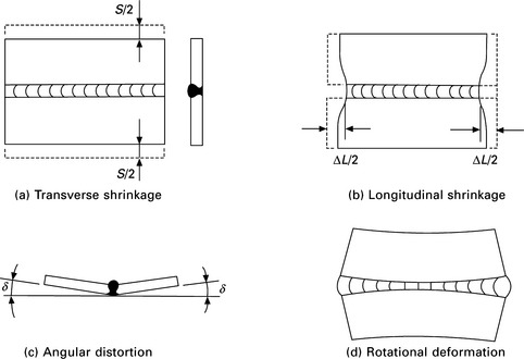
13.1 Typical welding distortions: (a) transverse shrinkage; (b) longitudinal shrinkage; (c) angular distortion; (d) rotational deformation.
Figure 13.2 illustrates the distribution of welding residual stress on a butt welded plate. Figure 13.2(a) shows the distribution of longitudinal residual stress (component in welding direction) along the welding direction and the transverse section at the center. On the center section, the largest tensile residual stress is observed in the location around the welding line and the value reaches almost the yield stress when the material is mild steel. To keep the balance, small compressive stress is produced in the area away from the weld line. As for the distribution along the welding line, the longitudinal residual stresses at both ends become zero because of the free boundary. In the same manner, the distribution of the transverse residual stress is shown in Fig. 13.2(b). The transverse residual stress is tensile at the center and it is compressive at the start and finish ends of the welding line. The transverse residual stress becomes zero along both edges of the plate.
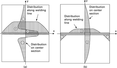
13.2 Schema of welding residual stress distribution: (a) stress in welding direction (b) stress in transverse direction.
As will be discussed in this chapter, the magnitude of the welding distortion and the residual stress are strongly influenced by the welding heat input. Generally, the magnitude of the welding distortion and the residual stress increase with the heat input. In this sense, high energy density welding such as laser welding is advantageous because it requires smaller heat input compared to conventional arc welding.
The welding distortion and the residual stress are produced as an undesirable consequence of the thermal cycle generated by the heat concentrated in a small area. The same mechanism can be utilized to form or bend plate to a desired curved shape by controlling the heat given to the plate. Since laser is superior in controllability, it can be used to form flat plate to arbitrary 3D curved shapes for shipbuilding applications and it can be employed for fine adjustment of the geometry of machine parts. Also it can be employed to mitigate or improve the residual stress distribution of welded structures, such as the pressure vessels in power plant.
13.2 Causes of residual stress and distortion
13.2.1 Mismatch and inherent strain
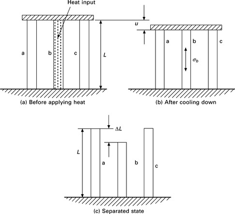
Welding residual stress and distortion are produced by mismatch of macroscopic scale (structural component level) and microscopic scale (strain level). Figure 13.3 shows a simple example of macroscopic mismatch. Three bars a, b and c are connected at both ends as shown in Fig. 13.3(a) and the bar b in the center is melted by heat and cooled down to room temperature. Since bar b shrinks during cooling, the connected three bars shrink as shown in Fig. 13.3(b). The deformation corresponding to this shrinkage is the displacement u and compressive stresses σa and σc are produced in bars a and c. Tensile stress σb is produced in bar b. Figure 13.3(c) shows the lengths of three bars separated by cutting. Because of the thermal cycle, the length of bar b becomes shorter than the other two by ΔL. This difference of length ΔL is the mismatch and it produces the distortion u and the residual stresses σa, σb and σc.
At this stage, it is worth noting that the distortion and the residual stress can be estimated if the mismatch ΔL is known. Let Aa, Ab, Ac be the cross-sectional area of three bars and E is the Young’s modulus. Then the deformation of the three bars joined together u and the residual stresses σa, σb, σc are obtained as:
In the above equations, k represents the stiffness of bar b and k* represents the sum of the stiffnesses of bars a and c, i.e.:
Then the parameter β defined by the following equation means the degree of restraint from bars a and c on bar b.
When the restraint is small, in other words (k* ![]() k), β ≈ 0. If the restraint is large (k*
k), β ≈ 0. If the restraint is large (k* ![]() k), β ≈ 1. Applying these relations to Eq. [13.1] and Eq. [13.3], it is readily seen that the mismatch turns into the deformation, and stress is not produced when the restraint is extremely small, i.e:
k), β ≈ 1. Applying these relations to Eq. [13.1] and Eq. [13.3], it is readily seen that the mismatch turns into the deformation, and stress is not produced when the restraint is extremely small, i.e:
If the restraint is extremely large, the mismatch turns into stress and no deformation is produced, i.e.:
The microscopic mismatch can be explained using decomposition of strain into its components. The total strain ε can be decomposed into the sum of the elastic strain εe, the plastic strain εp, the thermal strain εT, the creep strain εc and that produced through phase transformation εt, i.e:
Noting that the deformation and the stress are produced by the total strain ε and the elastic strain εe, Eq. [13.9] can be rearranged to:
This equation means that the distortion ε and the residual stress εe are produced by the inherent strain ε* which consists of the plastic, the thermal, the creep strains and that caused by the phase transformation. The inherent strain is sometimes called ‘misfit strain’. Though the detail is not explained here, the distortion and the residual stress after welding can be computed by elastic analysis if the distribution of the inherent strain ε* is known as in the case of the mismatch ΔL in the three-bar model.
13.2.2 Inherent strain and deformation in thin plate
Welding deformations in thin plate, such as the transverse shrinkage, longitudinal shrinkage and angular distortion shown in Fig. 13.1, are mostly produced by the longitudinal and the transverse inherent strains εx* and εy* where x, y and z are coordinates taken in the welding, the width and the thickness directions. By integrating the inherent strain over the cross section normal to the welding line and taking the average through the thickness h, the inherent deformations are obtained:
Among the above four components of the inherent deformation, three components except the longitudinal bending are important components in the distortion of welded structures. The inherent deformations can be calculated from the computed results by finite element analysis according to Eqs [13.11]–[13.14]. They can be also measured by experiments and used to predict the welding distortion of large-scale complex real structures (Murakawa et al., 1998).
13.2.3 Inherent stress and inherent force in thin plate
As the inherent deformation is defined based on the concept of the inherent strain, inherent stress and inherent force can be defined as relevant concepts. Through the constitutive relation, the inherent strains εx*, εy* are transformed into inherent stresses σx*, σy*:
Further, the inherent forces and the inherent moments can be defined by the following equations.
As explained, the mismatch (inherent deformation) turns into deformation when the restraint is small and it turns into force when the restraint is large. It is natural to use the inherent strain or deformation for the transverse direction in which the restraint is small and to use the inherent stress or force for the longitudinal direction in which the restraint is large.
13.3 Mechanism of formation of longitudinal and transverse shrinkage of welded joints
13.3.1 Inherent strain in three-bar model subjected to thermal cycle
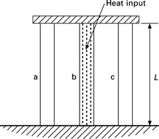
As discussed, the welding distortion and the residual stress are caused by the mismatch in microscopic and macroscopic scales or the inherent strain and the inherent deformation. In this section, the mechanism by which the inherent strain and the inherent deformation are produced is explained using a simple model that consists of three bars, a, b and c as shown in Fig. 13.4. In this model, there is no mismatch in the beginning and the initial length of the three bars is L.
If the temperature of bar b is raised by T °C in the heating process and the thermal expansion ratio is α, the length of bar b in stress-free state is increased by αTL due to the thermal expansion. The stress σb acting on bar b can be obtained by substituting this value into Eq. [13.3] as the mismatch ΔL, i.e.:
Assuming E = 200 GPa, α = 10‒5 1/°C, the thermal stress induced in the steel bar which is fully restrained (β = 1) becomes
If the yield stress is 300 MPa, the stress reaches the yield stress when the temperature becomes 150 °C and plastic deformation is produced during the further increase in temperature.
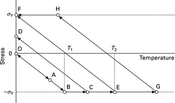
As a general case, the case in which 0 < β < 1 and the thermal cycle is 0 °C → Tmax °C → 0 °C is considered. The time history of the stress during the thermal cycle can be divided into three types depending on the maximum temperature reached Tmax as shown in Fig. 13.5:
Since the thermal stress remains below the yield stress, no plastic strain or inherent strain εb* is produced.
2. T1 < Tmax < T2 (O → B → C → D)
Compressive plastic strain is produced only in the heating process.
3. T2 < Tmax (O → B → G → H → F)
Compressive plastic strain is produced in the heating process. Then tensile plastic strain is produced in the cooling process. As a result, compressive plastic strain remains as the inherent strain.
Though the details of the derivation are not shown, the relation between the highest temperature reached Tmax, the inherent strain εb* and the residual stress σb are summarized as follows:
The above equations can be used to calculate the longitudinal shrinkage δL* or the tendon force F*L as will be discussed in the next section. Also, Eqs [13.29] and [13.27] tell us that critical temperature T1, which corresponds to the transition point of the inherent strain, becomes high and the maximum value of the inherent strain εb* becomes large when the restraint β is small.
13.3.2 Welding deformations in longitudinal and transverse direction
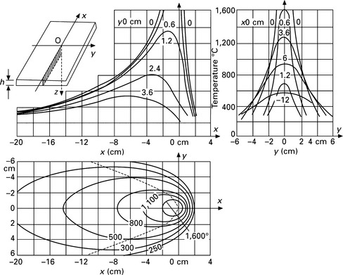
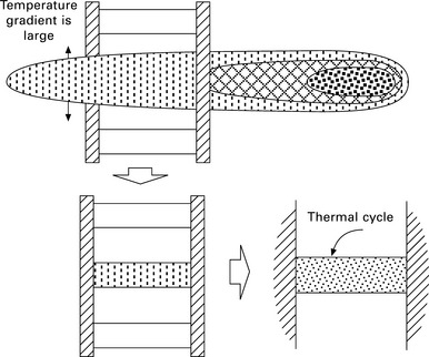
If the temperature distribution in a structure is uniform and there is no external restraint, neither residual stress nor distortion is produced by the thermal cycle. However, the metal is melted and joined by applying concentrated heat to a small area in welding. The temperature distribution in welding is not uniform and it changes with time. Figure 13.6 illustrates the temperature distribution during butt welding. The highest temperature is observed at the position of the heat source and the equitherms near the heat source are ellipsoids close to circles. As they move away from the heat source, the equitherms become long ellipsoids. This means that the temperature gradient near the heat source is large and that in the welding direction and the transverse direction is roughly of the same order. At the point behind the heat source, the temperature gradient in the transverse direction is large while that in the welding direction is small.
The temperature gradient can be related to the restraint using the three-bar model. Figure 13.7 illustrates the temperature distribution and the restraint in the welding direction which produce longitudinal residual stress. Since the temperature gradient is large in the transverse direction, the area close to the weld can be considered as the heated bar b in the center. The remaining areas on both sides of the weld, corresponding to bars a and c, have large stiffness and their temperature is close to room temperature. The temperature distribution in each bar is assumed to be uniform for simplicity. It is readily understood that large tensile residual stress is produced in the weld zone due to the large restraint and the shrinkage in the welding direction is small for the same reason.
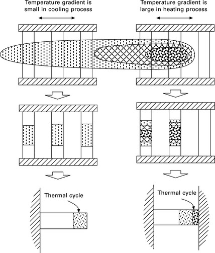
Similarly, the illustration for the transverse stress and deformation is given in Fig. 13.8. As shown in the figure, the temperature gradient in the heating and the cooling processes are different. The temperature gradient in the welding direction in the heating process is large while that in the cooling process is small. Since the restraint in the heating process is large and the yield stress of the bars in the center and that just behind the heat source is small, the thermal expansion of these bars is fully transformed into the compressive plastic deformation. Thus, the shrinkage of these bars due to the plastic deformation δT* is equal to the thermal expansion, i.e.:
where Q is heat input, ρ is density, c is specific heat, and h is thickness of plate. In the cooling process, the restraint becomes small due to the small temperature gradient in the longitudinal direction. Since the restraint and the stress are small, additional plastic deformation is not produced and the width of the plate becomes smaller by δT* = αQ/cρh after welding.
As is demonstrated through a simple three-bar model, the processes by which the stress and the deformation are formed are different between the welding and the transverse directions.
13.4 Influential factors on welding distortion and residual stress
The fundamental components of local deformations or the inherent deformations are the transverse shrinkage, the longitudinal shrinkage and the angular distortion shown in Fig. 13.1. The deformations, such as the longitudinal bending of beam, the buckling deformation and the twisting deformation shown in Fig. 13.9, are produced by the combination of the above fundamental components. Thus, if these inherent deformations are known, the distortion of the welded structure can be predicted by an elastic analysis (Murakawa et al., 1998).
13.4.1 Transverse shrinkage and angular distortions
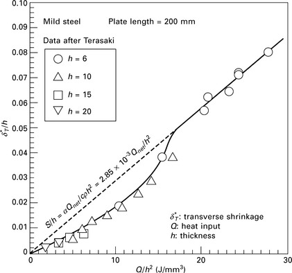
In case of arc welding, Satoh and Terasaki (1976) showed that the transverse shrinkage δT* can be consistently related to the heat input parameter Q/h2, where Q and h are welding heat input per unit length and thickness of plate, respectively. Figure 13.10 shows the relation between the transverse shrinkage and the heat input parameter Q/h2 for mild steel under arc welding. The heat input Q can be estimated by the following formula:
where η is heat efficiency, I is welding current, U is welding voltage and v is welding speed.
The parameter Q/h2 indicates the relative size of heat input compared to the plate thickness. When this parameter is small, only the part of the metal close to the surface along the weld bead is heated above the mechanical melting point (in the case of mild steel, it is roughly 700–800 °C). When the parameter is greater than 20 J/mm3, the temperature reaches the mechanical melting point throughout the thickness. In such cases, the measured points are plotted along a line and the linear relation holds between the transverse shrinkage δT* and the parameter Qlh2. This corresponds to the fact that the transverse shrinkage is roughly equal to the thermal expansion caused by the heat input. If mild steel is taken as an example:
By substituting the above material constants into Eq. [13.32], the following relation is obtained:
The proportional constant 3.3 × 10‒3 is close to the slope of the line in Fig. 13.10, which is 2.85 × 10‒3. If the heat input parameter is smaller than 20 J/mm3, the shrinkage becomes smaller than the value corresponding to this line. This can be explained by the fact that the restraint from the region near the back surface of the plate, where the temperature is below the mechanical melting temperature, becomes large.
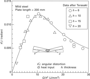
Similarly, Fig. 13.11 shows the relation between the angular distortion θT* and the net heat input Q. The angular distortion is produced by the through-thickness temperature gradient. This is observed when the heat input is small and the plate is melted partially in the thickness direction. The angular distortion increases almost linearly with the heat input parameter up to Q/h2 = 10 GJ/m3. When the parameter is larger than this, the angular distortion decreases with the parameter because the through-thickness temperature gradient becomes small.
13.4.2 Longitudinal shrinkage
Unlike the transverse shrinkage and the angular distortion, which can be directly represented as deformations, the longitudinal shrinkage is represented as the tendon force FL*. As explained, the inherent deformation is reflected directly to the deformation when the restraint is small, while it is reflected mainly to the force or the stress when the restraint is large. Thus, it is quite natural to describe the longitudinal shrinkage in terms of the force.
According to White et al. (1980), the tendon force F*L is proportional to the net heat input Q, i.e.:
White et al. proposed 200 as the proportional constant a. As discussed in the above, the transverse shrinkage, the angular distortion and the longitudinal shrinkage are basically proportional to the heat input Q.
The formula given by Eq. [13.35] can be derived from Eqs [13.24], [13.26] and [13.28]. When the butt welding of two plates with large enough width is considered, the restraint in the welding direction is very large so that the plane normal to the weld line can be assumed to be fully fixed. When the plate is thin, the highest temperature reached at the point y away from the center line of the weld Tmax (y) is approximated as:
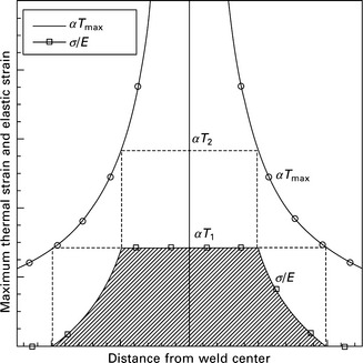
Using Eqs [13.24], [13.26], [13.28] and [13.36], the distribution of the residual stress component in the welding direction can be drawn as in Fig. 13.12. Further its integration over the transverse cross section gives the tendon force FL*:
If the material is mild steel, the constant α becomes 233 and this value roughly agrees with the value proposed by White et al. Further dividing the tendon force by the stiffness of the cross section EBh, average strain in the longitudinal direction εL is obtained:
where B is the breadth of the plate. It is noticed from the above equation that the Young’s modulus is involved in the tendon force but not in the longitudinal strain εL.
As shown in Fig. 13.12, the widths of the residual stress distribution B1* and B2* are determined by the temperature T1 and T2. From Eq. [13.36], T1, T2 and B1*, B2* are related through the following equations:
the widths of residual stress distribution B1* and B2* are given by:
The above equation tells us that the width of the residual stress distribution is also proportional to the heat input Q. And they are proportional to the Young’s modulus E and the thermal expansion ratio α, and they are inversely proportional to the yield stress σY, specific heat c, density ρ and thickness h.
13.4.3 Buckling due to welding
Since the buckling is a nonlinear problem, it is difficult to explain it in a simple manner. Noting that the phenomena is linear up to the onset of buckling, it is relatively easy to discuss the critical heat input Qcr at which the plate starts to buckle by the residual stress produced by welding, and it can be easily shown that Qcr is proportional to (cρ/α)(h3/B). For simplicity, let’s consider a square plate with stiffeners welded along four edges. The distribution of the welding residual stress in the plate is roughly approximated as shown in Fig. 13.13. The buckling is driven by the compressive residual stress σR distributing in the center part of the plate. When the equilibrium is assumed, σR must be in balance with the tensile stress distributing near the weld line or the tendon force FL*. Further, the tendon force can be related to the heat input Q through Eq. [13.35]. i.e.:
On the other hand, buckling stress σcr is given by the following equation:
where k is a constant determined by the aspect ratio and the boundary condition of the plate. Noting that the plate buckles when the welding residual stress σR reaches the buckling stress σcr, the critical heat input Qcr is shown to be:
The above equation tells us that Qcr is proportional to (cp/α)(h3/B).
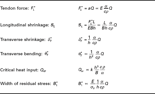
As summarized in Table 13.1, the magnitudes of various types of welding deformations and the width of residual stress distribution can be related to the heat input Q and other parameters. All deformations and the width of residual stress distribution are linearly related to the heat input Q and the parameter α/cρ. It is also seen that the Young’s modulus and the yield stress do not appear as primary factors except for the tendon force and the width of residual stress distribution.
13.5 Distortion and residual stress produced by laser welding
13.5.1 Welding distortion and its control
Laser welding is effective in reducing the distortion because of the small heat input resulting from deep and narrow weld seams compared with arc welding. For further improvement, influence of the welding power and welding speed on distortion and residual stress of laser beam welded shaft-hub joints was investigated by Buschenhenke et al. (2010), who reported that high brightness lasers generate deeper welds with higher aspect ratio but this leads to higher tensile stress levels and is not necessarily beneficial for deformation. The deformation can be reduced at the higher welding speed with large laser power as shown in Fig. 13.14. Also the effectiveness of the multi-beam laser shown in Fig. 13.15 has been investigated (Buschenhenke et al., 2011). Figure 13.16 shows the distortions such as dishing slope and tilt measured and computed for single-beam and multi-beams. As seen from the figure, the tilt is significantly reduced by two beams on one side and the dishing can be reduced by two beams on the face and back sides. It is also shown in this report that dense tack welds are effective in controlling the tilt.
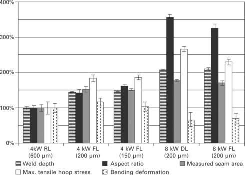
13.14 Influence of welding condition on residual stress and distortion (Buschenhenke et al., 2010).
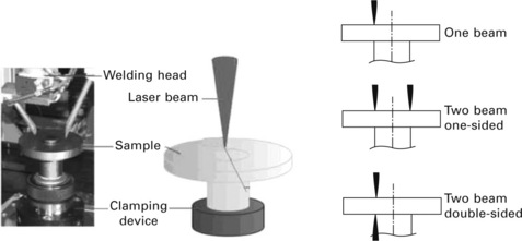
13.15 Welding set-up with one laser beam and the schematic overview of all beam positions (Buschenhenke et al., 2011).
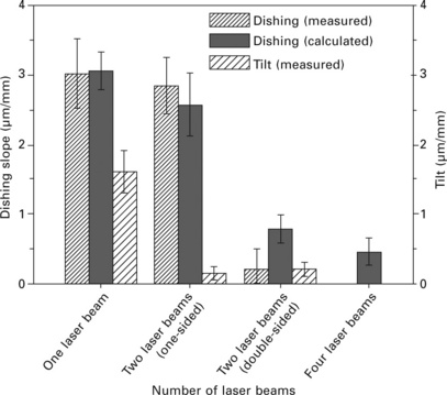
13.16 Effectiveness of multi-beam laser welding to reduce distortions such as dishing slope and tilt (Buschenhenke et al., 2011).
13.5.2 Residual stress
Zhang et al. (2010) investigated multi-pass narrow gap laser welding of austenitic stainless steels. Thick stainless steels are welded by three welding methods, namely LBW, GTAW and GTAW + SMAW. Figure 13.17 shows the distribution of residual stresses measured on the surface of the specimen. As seen from the figure, the maximal value of the residual stress perpendicular to the welding bead for the laser welded joint is lower than those of the conventional GTAW. As for the width of residual stress distribution, the width for the laser welding is smaller than GTAW in both residual stresses perpendicular and parallel to the welding. This is because the heat input for the laser welding is small and this agrees with Table 13.1, which shows that the width of residual stress distribution is proportional to the heat input.
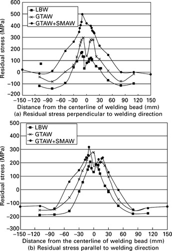
13.17 Residual stresses of LBW, GTAW and GTAW + SMAW (Zhang et al., 2010).
In the case of laser powder deposition, the effect of the deposition pattern on the temperature and stress distribution has been studied by Foroozmehr and Kovacevic (2009). Figure 13.18 shows three deposition patterns tested and Plate XII (between pages 328 and 329) shows the influence of deposition pattern on the computed residual stress. It is reported that dividing the area under deposition into smaller areas results in less variation in temperature with a higher average temperature during the process. The stress distribution along the deposition direction and perpendicular to that direction are changed as a result of changing the deposition pattern. The results have a close agreement with the X-ray diffraction residual stress measurements. Similarly, Chae and Mazumder (2011) investigated how the residual stress in laser direct metal deposition is developed over time. Also the effects of the laser power on thermal behavior such as melt pool size and temperature field have been studied.
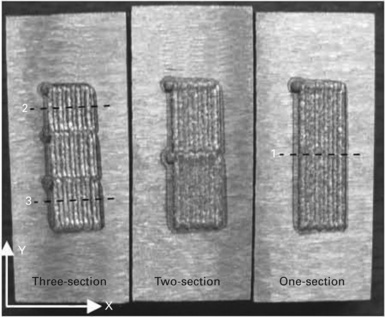
13.18 Coupons made with different deposition patterns (Foroozmehr and Kavacevic, 2009).
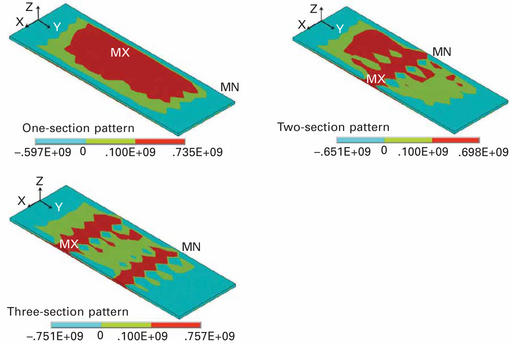
Plate XII Computed effect of deposition pattern on residual stress distribution (from Foroozmehr F and Kovacevic R (2009) ´Effect of path planning on residual stress distribution in laser powder deposition process´, Proceedings of ICALEO´09, 830–839).
13.5.3 Prediction by simulation
There are two simulation methods which can be employed for the prediction of welding distortions and residual stresses. One is the thermal elastic plastic finite element analysis, in which the welding is treated as a transient nonlinear problem (Ueda and Yamakawa, 1971). The other is the inherent strain method, in which the distortion and residual stress are computed by elastic analysis using the inherent strain as initial strain (Ueda et al., 1977; Murakawa et al., 1998). They have both advantages and disadvantages. The latter is advantageous in computational time and disadvantageous because the detail of the welding condition, such as the gap control and fitting, may not be fully considered in some cases. To predict the welding distortion and the residual stress of large-scale structures, methods combining these two are proposed as a practical approach.
A local–global finite element approach (Tsirkas et al., 2003b) is one of the combined methods to predict welding distortions of large structures. Figure 13.19 shows the distortions of a member of a ship structure assembled in two different sequences by laser welding. The local approach takes into account thermal, metallurgical and mechanical aspects of the laser welding process. The simulation of the laser welding process was performed using a nonlinear heat transfer analysis, based on a keyhole formation model, and a coupled transient thermomechanical analysis. The global approach involves the transfer of residual plastic strains and the stiffness of the weld, obtained from the local model, to the global analysis, which provides the distortions in the member. The developed methodology was applied to the evaluation of global distortions due to laser welding of stiffeners on a plate.
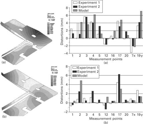
13.19 Predicted distortions of a ship structure member assembled in two different sequences by laser welding (Tsirkas et al., 2003b).
The thermal elastic plastic finite element method was employed to predict distortions of various types of joints, such as butt joints (Tsirkas et al., 2003a; Arai and Asano, 2009) and aluminum lap joints (Moraitis and Labeas, 2008).
13.5.4 Laser forming
Since laser is superior in controllability compared to other heat sources, such as gas frame and arc, it can be applied to forming three-dimensional doubly curved shapes from a flat plate. The mechanism of deformation during the forming process is the same as in the case of welding deformation. By selecting process parameters, such as the power, beam diameter and scanning speed, the laser can be applied to structures with a wide range of plate thicknesses from thick plate for ship structures (Romero et al., 2011) to thin sheet metals (Jamil et al., 2010). In the case of application to shipbuilding industries, Plate XIII (between pages 328 and 329) shows the computed deformation of plate after forming by CO2 laser. Computer simulation has a great potential in the design of the forming procedure. Simulation of the process to form a bowl shape from a circular plate (Venkadeshwaran et al., 2009) and the simulation of laser forming of the particle reinforced metal matrix composites (Liu et al., 2009) have been reported. Attempts have also been made to predict the deformation in the laser forming process using an analytical method (Kyrsanidi et al., 2000).
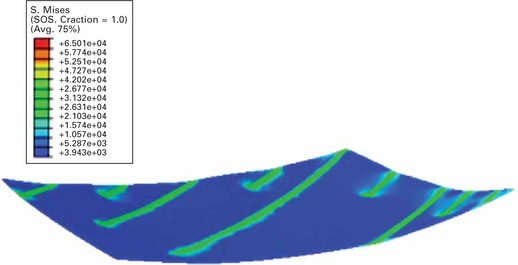
Plate XIII Computed deformation of plate after forming by CO2 laser (from Romero P, Otero N, Pintos V, Arias R (2011) ‘Experimental analysis of automated laser forming for shipbuilding industry’, Proceedings of ICALEO’ll, 1272–1279).
When the plate is relatively thick, the plastic strain produced by the thermal load can be employed. In the case of very thin plate, the plastic strain produced by micro shockwave (Bechtold et al., 2009), illustrated in Fig. 13.20, can be employed and this type of forming method can be used for fine adjustment of geometry of thin metal parts.
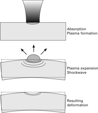
13.20 Mechanism of laser forming by micro shockwave (Bechtold et al., 2009).
13.5.5 Problems to be tackled
Judging from the amount of literature reporting the simulation of the laser welding process, it is clear that theoretical prediction is a powerful means to understand how the deformation and residual stresses develop. It is also useful to identify the influential factors to reduce the distortion and the residual stress. To obtain reliable conclusions from the simulations, the modeling of the heat source is very important as in the case of arc welding. In the case of the laser welding, development of an accurate and simple keyhole model is necessary.
13.6 References
Arai, T., Asano, N., Simulation of thin metal deformation by laser welding. Proceedings of ICALEO’ 2009; 09:676–683.
Bechtold, P., Roth, S., Schmidt, M., Analysis and application of micro shockwave adjustment using ultrashort laser pulses. Proceedings of ICALEO’ 2009; 09:1124–1133.
Buschenhenke, F., Hofmann, M., Seefeld, T., Vollertsen, F., Distortion and residual stress in laser beam welded shaft-hub joints. Proceedings of ICALEO’ 2010; 10:389–397.
Buschenhenke, F., Seefeld, T., Vollertsen, F., Distortion control during laser beam welding of shaft-hub joints within a process chain. Proceedings of ICALEO’ 2011; 11:427–434.
Chae, H. M., Mazumder, J., Effects of melt pool size on transient and residual stress in DMD process. Proceedings of ICALEO’ 2011; 11:267–274.
Foroozmehr, F., Kovacevic, R., Effect of path planning on residual stress distribution in laser powder deposition process. Proceedings of ICALEO’ 2009; 09:830–839.
Jamil, M. S. C., Pinkerton, A. J., Li, L., Sheikh, M. A., The effect of beam geometry on diode laser forming of sheet metals. Proceedings of ICALEO’ 2010; 10:495–502.
Kyrsanidi An, K., Kermanidis Th, B., Pantelakis Sp, G. An analytical model for the prediction of distortions caused by the laser forming process. Journal of Materials Processing Technology. 2000; 104:94–102.
Liu, F. R., Chan, K. C., Tang, C. Y., Investigations on interface debonding of the particle reinforced metal matrix composites in laser forming. Proceedings of ICALEO’ 2009; 09:. [Paper No. 503].
Moraitis, G. A., Labeas, G. N. Residual stress and distortion calculation of laser beam welding for aluminum lap joints. Journal of Materials Processing Technology. 2008; 19(8):260–269.
Murakawa, H., Luo, Y., Ueda, Y. Inherent strain as an interface between computational welding mechanics and its industrial application. In: Cerjak H., ed. Mathematical Modelling of Weld Phenomena 4. London: Minerals and Mining, Institute of Materials; 1998:597–619.
Romero, P., Otero, N., Pintos, V., Arias, R., Experimental analysis of automated laser forming for shipbuilding industry. Proceedings of ICALEO’ 2011; 11:1272–1279.
Satoh, K., Terasaki, T. Effect of welding conditions on welding deformations in welded structural materials. Journal of the Japan Welding Society. 1976; 45(4):302–308.
Tsirkas, S. A., Papanikos, P., Kermanidis, T. Numerical simulation of the laser welding process in butt-joint specimens. Journal of Materials Processing Technology. 2003; 134:59–69.
Tsirkas, S. A., Papanikos, P., Pericleous, K., Strusevich, N., Boitout, F., Bergheau, J. M. Evaluation of distortions in laser welded shipbuilding parts using local–global finite element approach. Science and Technology of Welding and Joining. 2003; 8(2):79–88.
Ueda, Y., Yamakawa, T. Thermal stress analysis of metals with temperature dependent mechanical properties. Trans. JWS. 1971; 2(2):90–100.
Ueda, Y., Fukuda, K., Nakacho, K., Endo, S. Fundamental concept in measurement of residual stresses based on finite element method and reliability of estimated values. Theoretical and Applied Mechanics. 1977; 25:539–554.
Venkadeshwaran, K., Das, S., Misra, D., 3D laser forming through circle line heating. Proceedings of ICALEO’ 2009; 09:233–239.
White, J. D., Leggatt, R. H., Dwight, J. B. Weld shrinkage prediction. Welding and Meal Fabrication. 1980; 11:587–596.
Zhang, X., Ashida, E., Tarasawa, S., Properties of welded joint for narrow gap laser welding of austenitic stainless steels. Proceedings of ICALEO’ 2010; 10:632–637.

