Developments in multi-pass laser welding technology with filler wire
Abstract:
This chapter presents the results of multi-pass laser welding of thick plates for type 316L stainless steels with filler wire. The lack of fusion can be prevented by optimizing the relationship between laser power intensity and the deposited metal volume. The solidification crack, which usually occurs in the weld metal of the build-up passes, can be suppressed by controlling the chemical composition of the filler wire. The maximal tensile residual stress and the range of the tensile stress of the laser welded joint are lower than those of the conventional gas tungsten arc welding (GTAW).
17.1 Introduction
Many thick-section structures are fabricated using welding in several industrial fields such as power plants, shipbuilding and pipelines. The welding processes for fabrication of these thick-section structures include traditional multi-pass arc welding, laser-arc hybrid welding, one-pass electron beam welding and laser welding. For arc welding, such as the application of narrow-gap arc welding, submerged arc welding and hot-wire tungsten inert gas welding, the production efficiency is limited by the low welding speed and too many weld passes. Furthermore, welding distortion is also a problem, and distortion correction is often needed after welding. In the past decade, electron beam welding1–3 and laser welding have been paid more attention for welding of thick-section stainless steels.4–9 They both are very high-efficiency and low-distortion process methods due to the features of ultra-deep penetration and very narrow weld bead width. For electron beam welding, the thickness to be penetrated for single-pass electron beam welding of stainless steels has been over 100 mm,2,3 As for laser welding, it can produce weld joint with smaller welding distortion and higher welding speed than arc welding, and the process can be performed in atmosphere with appropriate shielding gas. Although the penetration depth is still lower than that of electron beam at present, the process flexibility is a great advantage by combination of a laser beam with additional materials like a filler wire or powder, or by combination with an arc, which can permit larger gap tolerance and adjust the composition of the weld metal. Especially for thick-section steel plates of 30–60 mm or greater, multi-pass laser welding with a filler wire is one of the appropriate methods.
This chapter presents the process principle, welding parameters and welding results for multi-pass laser welding with a filler wire. All the experimental results are for laser welding of SUS316L steels with thicknesses of 30–60 mm.10–14 The exact results obtained for a welding operation depend on a wide variety of process parameters and vary with different laser welding systems. These parameters are not usually specified well enough to allow one to duplicate exactly the conditions for a particular process. Thus the tabulated and graphed data must be interpreted as indicating an approximate range of welding results that may be obtained. In order to obtain the best results, the welding parameters for a particular processing operation must be optimized experimentally.
17.2 Principle of multi-pass welding with filler wire
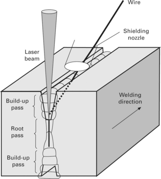
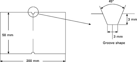
Multi-pass welding with a filler wire is one of the efficient methods for joining thick-section materials with a laser beam. It has been reported that 150 mm thick low carbon steels could be butt-jointed by narrow-gap laser welding with a filler wire.15 Multi-pass laser welding can be performed from one side or both sides. Figure 17.1 shows the schematic diagram of the experimental setup for multi-pass laser welding from both sides. A groove with a thick root face and small groove angle is often prepared. In order to reduce the total weld passes, the thickness of root face can be prepared as thick as possible, for the laser beam welding has high penetrating ability. As the smaller the angle of groove is, the less is the total deposited metal, the angle of groove should be set as small as possible. The root pass is usually performed without filler wire, but it is also possible for filler wire to be added. The subsequent build-up passes are performed by adding a filler wire. One of the major aspects that concerns the laser beam properties is that the laser beam must be assured to irradiate the groove bottom, so it is necessary to use a laser beam with small beam parameter product and a focusing lens with long focal length.
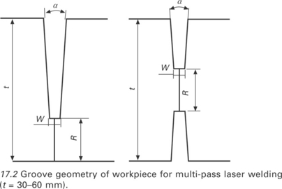
As an example, Fig. 17.2 shows the groove geometries of the workpieces for one side (Fig. 17.2(a)) and both sides (Fig. 17.2(b)) welding when using an 8 kW disk laser to perform welding. The thickness of the plate is 30–50 mm for one-side welding, and 60 mm for both-sides welding. The thickness of root face R is from 8 mm to 10 mm for one-side welding, and 10 mm to 15 mm for both-sides welding. The groove angle α is 4–5° and the width of root face W is 2–4 mm. The groove depth is from about 20 mm to 50 mm for different thick plates.
17.3 Developments in technology
17.3.1 Welding systems
The welding system for multi-pass laser welding with a filler wire consists of at least a laser oscillator, an optical system for transferring a laser beam, a laser process head, a shielding gas nozzle, and a system for feeding filler wire into the groove. The other additional equipment includes a monitoring system to check the welding process, and a seam-tracking system to guide the welding position.
Multi-pass welding with a filler wire is usually utilized for large-scale thick-section structures, so the process stability in long-time continuous welding is one of the most important aspects that concern the welding quality. The stability of welding process involves the stability of laser beam quality and the other welding conditions. In particular, the thermal focus shift, which is induced by the change in the position of focal point of the optical lenses, often happens in high-power laser welding and is not easy to detect. Figure 17.3 shows a sample of the instability of weld bead shape and penetration depth in bead-on-plate welding. The welding conditions are laser power of 10 kW, welding speed of 0.3 m/min and defocused distance of − 2 mm. The total welding time is 46 s and the length of the weld bead is 230 mm. It shows that at the beginning of welding, the weld surface is smooth (Fig. 17.3(a)) and the cross section shape is sound (Fig. 17.3(b)), but the weld surface becomes unstable, with large spatters, and the cross section shape also becomes narrow and underfill occurs near the end of the welding (Fig. 17.3(c)). The penetration depth is respectively decreased from 16.7 mm near the welding beginning to 14.7 mm near the welding end. Such instability in penetration depth and weld bead shape is considered to be related to the thermally induced focus shift of the focusing lens. Measures to prevent the thermal lens effect have to be taken for applications of high-power laser welding.
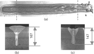
17.3 Instability of weld bead shape induced by thermal focus shift in laser welding10 (laser power 10 kW, welding speed 0.3 m/min): (a) weld surface; (b) cross section of weld bead near weld start; (c) weld cross section near weld end.
17.3.2 Welding parameters
Root-pass welding
The effect of welding conditions on the weld geometry of the root pass has been investigated with penetration welding of 30 mm thick plates without filler wire. The thickness of the root face is 10 mm. The result is shown in Fig. 17.4. Instability or variation of penetration depth occurs under some conditions if no backing plate is used in welding. The appropriate welding conditions for good weld bead geometry are 6 kW laser power and 0.5 m/ min welding speed. When the welding speed is increased to 0.75 m/min at 6 kW laser power, the weld bead becomes partial penetration. When the laser power is increased to 8 kW, the penetration bead becomes unstable at the welding speed of 0.8–1.2 m/min due to the excessive penetration, and partial penetration occurs at the welding speed of 1.5 m/min. It is predictable that the penetration bead is unstable when the welding speed is less than 0.8 m/ min for 8 kW laser power. Thus the appropriate welding parameter range is too narrow and, moreover, many spatters are stuck on the groove surface and the backside of the workpieces in the experiment when the laser power is 8 kW. Therefore, the welding parameters of 6 kW laser power and 0.5 m/min welding speed are adapted for the root-pass welding.
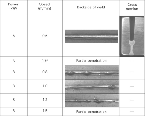
17.4 Results of root pass welding.13
Build-up welding
One of the most important aspects that concerns the weld quality in build-up multi-pass welding is ‘lack of fusion’. Build-up welding is performed under various welding conditions so as to study the relationship between welding conditions and weld bead geometry. The welding parameters are laser power 6 kW and 8 kW, welding speed 0.3 m/min and 0.4 m/min, and beam spot size at the welding point varying from 0.69 mm to 1.56 mm. The feeding speed of the filler wire is varied from 3.5 m/min to 8.0 m/min to get different build-up heights and deposition areas. The welding results show that lack of fusion occurs easily if the welding conditions are not appropriate, which is described in detail as follows.
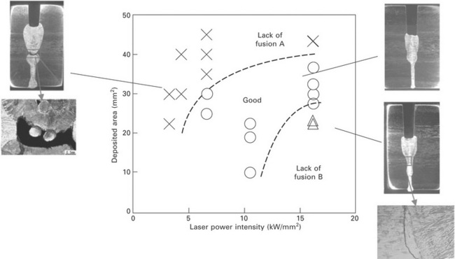
The typical weld bead geometries for the build-up welding, and the relationship between the welding conditions and the welding results are shown in Fig. 17.5. Two types of lack of fusion, lack of fusion A and lack of fusion B, are observed in the weld joint. In Fig. 17.5, the horizontal axis is labeled laser power intensity, and the vertical axis is labeled deposited area, which is the result of the wire feeding speed multiplied by the cross area of wire. It shows that when the laser power intensity is low and the deposited area is high, lack of fusion A tends to occur. The feature of lack of fusion A is that the weld bead formed in the initial root-pass welding is not re-melted during the following build-up welding, and as a result, lack of fusion occurs between the root weld bead and the build-up bead. In this case, non-fully melted wire is also observed. This is because the volume of wire fed into the welding zone is excessive and the melting ability of the laser beam is insufficient; as a result, even the filler wire cannot be fully melted. As the laser power intensity increases, lack of fusion A can be suppressed due to increases in the melting ability of laser energy, and good weld bead can be obtained in an appropriate range. However, if the laser power intensity is increased to very high level, lack of fusion B will readily occur.
The feature of lack of fusion B is that the side wall of the groove could not be melted and, as a result, there is lack of fusion occurring between the side wall of the groove and the deposited metal. The reason for lack of fusion B can be explained as follows: the volume of filler wire fed in the welding zone is not enough, resulting in the weld bead formed in root welding being re-melted by a deep and very narrow keyhole. The width of the penetration part induced by the keyhole is narrower than that of the groove, thus the groove wall near the upper of the root bead (or the bottom of the build-up bead) is not melted, leading to lack of fusion. In this case, the non-fully melted wire observed in lack of fusion A is not observed. Therefore, the relationship between deposited area and laser power intensity should be considered so as to prevent the lack of fusion.
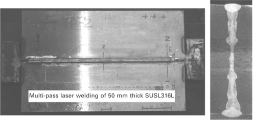
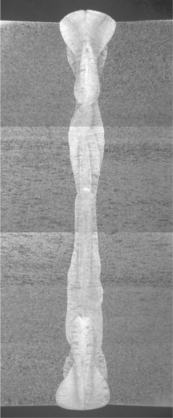
Figure 17.6 shows a sample of multi-pass laser welding of 50 mm thick stainless steel plates. The length of weld bead is 400 mm. The number of welding layers is 8, including two layers of root welding without filler wire, 4 layers of normal build-up welding, and 2 layers (4 passes) of reinforcement welding. No lack of fusion and porosity is found by optical microscope observation of the cross section of weld bead and X-ray inspection.
17.3.3 Example applications
This section presents welding results in terms of solidification cracking, microstructure and mechanical properties in applications of multi-pass welding for austenite stainless steel.
Welding crack and microstructure
Table 17.1 shows the compositions of the base metal and filler wires used in the welding experiment. Figure 17.7 shows the cross section of weld bead with crack and the microstructure of the weld metal near the crack. The crack usually occurs in the center of the build-up pass weld and is solidification cracking according to SEM observation. For this weld, the filler wire is wire A (Table 17.1) and its theoretical ferrite content should be about 5%. In the experiment, nitrogen is used as the shielding gas in order to suppress keyhole type porosity; however, the nitrogen content of the weld metal is much higher than that of the filler wire and the base metal, resulting in low ferrite content in the weld metal. Figure 17.7 indicates that the ratio of the ferrite microstructure near the crack is less than 1%, much less than that of the other zone. An increase of 300–400 ppm nitrogen of the weld metal compared with that of the base metal is also apparent. Considering that the nitrogen shielding gas decreases the ferrite content, filler wire with higher ferrite content should be used.
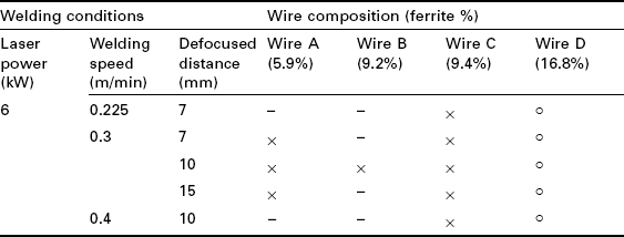
Table 17.2 shows the effect of welding conditions and wire composition (mainly the ferrite content) on the welding crack. The ferrite contents of the filler wires A, B, C and D are 5.9%, 9.2%, 9.4% and 16.8%, respectively. Under any conditions of welding speed and defocused distance of a laser beam at a laser power of 6 kW, cracks are observed in all the weld metals produced with wire A, wire B and wire C. When filler wire D with the ferrite content of 16.8% is used, however, no crack is found in the weld metal for all the welding conditions. The ferrite content of the weld metal is measured and it is found that the ferrite content of the weld metal is in the range of 6–11%. The decrease of 5.8–10.8% ferrite content of weld metal compared with the filler wire is the result of the nitrogen content increase in the weld metal due to the shielding gas of nitrogen. Therefore, it is suggested that increasing ferrite content of filler wire can prevent cracking. In addition, the increase in the ferrite content in the weld metal at room temperature should be correlated with the formation of a larger amount of ferrite phase during solidification.
Microstructure and mechanical properties
Figure 17.8 shows the microstructure of the weld metal for multi-pass welded 50 mm thick plates. The ferrite contents in the weld metal differ with welding pass, but the ferrite content is in the range of 7–11% for all layers.
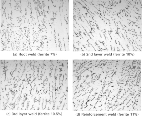
17.8 Microstructure of weld metal for multi-pass laser welding of 50 mm thick SUS316L plates.14
The results of the tensile test for the welded joint are shown in Table 17.3. It shows that the laser welded joints have enough tensile strength compared with that of the base metal, and also satisfy the specification of the base metal.
Table 17.3
| Welded joint | Base metal | |
| Tensile strength (MPa) | 577 | 551 |
| 0.2% yield strength (MPa) | 294 | 236 |
Figure 17.9 shows the distribution of hardness of weld metal and the base metal near the weld bead. The hardness of the weld bead and the hardness at 3 mm from the fusion boundary is in the range from 180 Hv to 220 Hv, which is greater than the hardness of the base metal (150–160 Hv). As the distance from the fusion boundary increases, the hardness decreases. The value of hardness shows the same level as that of the conventional GTAW.
Residual stresses
The residual stresses on the surface of the laser welded joint with 50 mm thickness are measured. The distribution of residual stresses perpendicular to the welding direction and parallel to welding direction are shown in Fig. 17.10(a) and (b), respectively. To compare the residual stresses of laser beam welding (LBW) with GTAW and shielded metal arc welding (SMAW), the residual stresses of GTAW and GTAW + SMAW joints16 are also shown in Fig. 17.10. It shows that the residual stresses of laser welded joints have the same tendency as that of GTAW and GTAW + SMAW joints. The maximum value of tensile stress is near the centerline of the welding bead. The tensile stress decreases as the distance from the centerline of the welding bead increases, and the stress changes to be compressive at the areas far away from the welding bead. The maximum value of tensile residual stress and the tensile range of stresses are different in LBW, GTAW and SMAW joints. Compared with GTAW, the maximal tensile residual stress is lower and the tensile range (above 0 mPa of stress) is narrower for a laser welded joint. This is probably because of the different angles of the grooves for different welding methods, which results in different total heat inputs and the volume of the weld bead. The narrower welding groove, lower heat input and fewer weld passes for laser welding lead to lower residual stress.
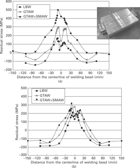
17.10 Residual stresses of LBW, GTAW and GTAW+SMAW.14 (a) Residual stress perpendicular to welding direction (b) Residual stress parallel to welding direction.
17.4 Future trends: further improvement of welding efficiency
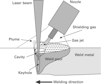
The number of welding passes need to be reduced further from the standpoint of process productivity; however, the thickness of the root pass is dependent on the penetration capability of the laser beam. For instance, the penetration is about 18 mm for welding stainless steel under the conditions of laser power 10 kW and 0.3 m/min welding speed.10 One of the possible methods to increase the penetration is to use a side gas jet.11–13,17 Figure 17.11 shows the schematic diagram of gas jet assisted laser welding. The main feature of this method is that the keyhole opening is deepened and widened by high pressure gas flow, so that the laser beam can enter the keyhole inside directly under no interaction with the surface of the molten pool at the keyhole opening. In this case, the keyhole depth can be increased and the penetration depth can be improved greatly, which has the same meaning as the use of higher power laser. In the next subsections, the difference between the gas jet assisted laser welding and the conventional laser welding is discussed, and then the results of the butt-joint welding of 40 mm thick plates and 50 mm thick plates are presented.11–13
17.4.1 Comparison between conventional and gas jet assisted laser welding
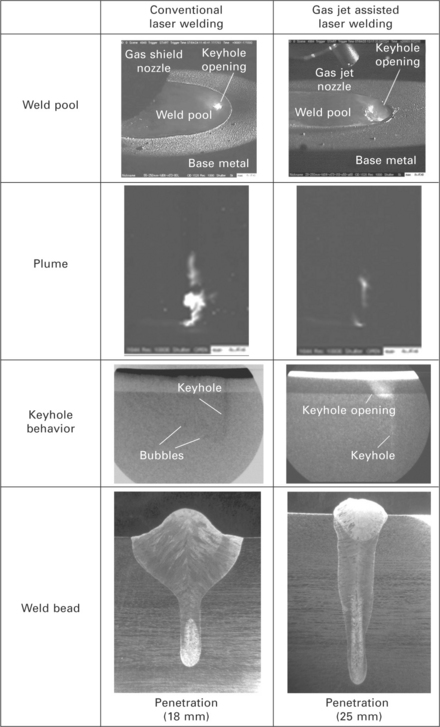
In order to understand the mechanisms of the penetration depth improvement induced by side gas jet, the keyhole behavior and the metal flow in gas jet assisted laser welding are investigated with high-speed cameras and X-ray transmission observation. Figure 17.12 shows a comparison between the conventional laser welding and gas jet assisted laser welding for bead-on-plate welding of 30 mm thick plates. The welding conditions are the same 10 kW laser power, 0.3 m/min welding speed and argon as the shielding gas for both processes. The different parameters between the two processes are the gas flow rate of the inner gas jet. The gas flow rate of the inner gas jet nozzle is set to 0 for the conventional laser welding, and 12 l/min for the gas jet assisted laser welding.
The welding phenomena and results for the conventional laser welding are shown in the left of Fig. 17.12. The photo of the weld pool, which is taken by high-speed camera, shows that for conventional laser welding without gas jet, a wide and flat surface of the molten pool is formed during welding (in the case of good shielding condition), but the keyhole opening is very small and melt metal with some extent of thickness exists between the front edges of the keyhole and the molten pool. The photo of the plume shows that a very strong and severely fluctuating plume is injected from the keyhole during welding. The keyhole behavior observed by the X-ray transmission apparatus shows that the keyhole presents a very narrow line shape, many bubbles form near the bottom of the keyhole, and some bubbles result in porosities during solidification. The photo of the cross section of weld bead shows that a wine-cup shape weld of about 18 mm in penetration and 17 mm in width is formed.
The welding phenomena and results for gas jet assisted laser welding are shown in the right of Fig. 17.12. For gas assisted laser welding, the weld pool becomes narrower and the keyhole opening is enlarged and deepened considerably, and the thickness of the melt metal between the keyhole front and the molten pool front also becomes thinner. The plume induced in the process is much weaker and more stable, and the height of the plume is also much lower than that of conventional laser welding without gas jet. From the X-ray in-situ observation, the keyhole shows different behavior, and the opening of the keyhole is significantly deepened and enlarged to form a cavity of about 3 mm in diameter and 3 mm in depth. In this case, the laser beam could be directly irradiated on the bottom of the keyhole opening under the conditions of no obstacles by removing the molten metal, resulting in a considerably deepened keyhole. As a result, the penetration depth is greatly increased to 25 mm at the same laser power and welding speed. Because of the formation of a deep keyhole opening, the defocused distance can be set to a greater minus value in order to get a deeper keyhole.
Another difference between the conventional laser welding and gas jet assisted laser welding is the weld appearance. The reinforcement height of the weld in conventional laser welding is less than 0.3 mm in the experiment. For gas jet assisted laser welding, however, the reinforcement height is about 3.0 mm even if no filler wire is used in the process. That is because the gas jet pushed the molten metal around the keyhole to flow backward and a weld bead with excessively high reinforcement is formed.
17.4.2 I-butt joint welding of 40 mm thick plates without filler wire
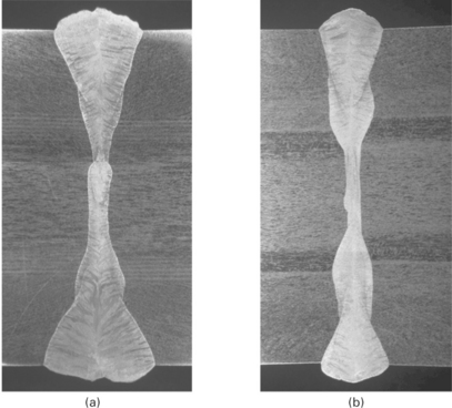
I-butt joint welding is undertaken on type 316L steel plates of 200 mm length, 100 mm width and 40 mm thickness, at the laser power of 10 kW. Two joints are welded: one is welded at 0.2 m/min welding speed, and the other at 0.3 m/min. Figure 17.13 shows the photos of the cross sections of weld beads. At the welding speed of either 0.2 m/min or 0.3 m/min, a regularly shaped bead without any lack of fusion and porosity is obtained in the welded joint. The width of the bead surface at 0.2 m/min welding speed is wider than that at 0.3 m/min. It shows that for butt-joint welding of 40 mm thick plates, a fully penetrated good joint can be obtained with a 10 kW laser in two passes, and penetrated from both sides without filler wire, by using the gas jet assisted laser welding method.
17.4.3 I-butt joint welding of 50 mm thick plates with filler wire
I-butt joint welding of 50 mm thick plates is tried by combining gas jet assisted welding and multi-pass welding with a filler wire. The geometry of the test piece used in the experiment is shown in Fig. 17.14. The welding is performed from both sides. The welding conditions and the welding results are shown in Fig. 17.15. The number of passes is four, including two passes of deep penetration laser welding with gas jet and two passes of repair welding with a filler wire. It shows a regularly shaped weld bead and no lack of fusion and porosity.
17.5 References
1. Takano, G., Shimoyama, T., Uratani, Y., Kuri, S. Study on weldability of electron beam welding for thick plate of austenitic stainless steel (Report 1): Selection of welding conditions and prevention of weld defects. Transactions of The Japan Welding Society. 1983; 14(2):10–19.
2. Kim, D. H., Kim, B. Y., Cho, S., Jung, K. J., Choi, I. S., Choi, M. H., Kim, I. H., Lee, G. Y. Welding technology development for the fabrication of ITER blanket shield block in Korea. Fusion Science and Technology. 2009; 56(1):43–47.
3. Jones, L., Alfile, J. -P., Aubert, P., Punshon, C., Danner, W., Kujanpaa, V., Maisonnier, D., Serre, M., Schreck, G., Wykes, M. Advanced cutting, welding and inspection methods for vacuum vessel assembly and maintenance. Fusion Engineering and Design. 2002; 51–52:985–991.
4. Vollertsen, F., Thomy, F., Welding with fiber laser from 200W to 17000W ICALEO2005. 2007:254–263.
5. Kinishita, K., Mizutani, M., Kawahito, Y., Katayama, S., ‘Phenomena of welding with high-power fiber laser’, ICALEO2006, paper 902. 2006.
6. Arata, Y., Maruo, H., Miyamoto, I., Nishio, R. High power CO2 laser welding of thick plate. Transactions of JWRI. 1986; 15(2):27–34.
7. Vollertsen, F., Grunenwald, S., ‘Defects and process tolerances in welding of thick plates’, 1CALEO2008, paper 1004. 2008.
8. Jokinen, T., Karhu, M., Kujanpää, V. Welding of thick austenitic stainless steel using Nd:yttrium-aluminum-garnet laser with filler wire and hybrid process. Journal of Laser Applications. 2008; 15(4):220–224.
9. Coste, F., Sabatier, L., Dubet, O., Aubert, P., ‘Nd:Yag laser welding of 60 mm thick 316L parts using multiple passes’, ICALEO2001, paper 514. 2001.
10. Zhang, X., Ashida, E., Mizutani, M., Katayama, S., Anma, Y., Luo, X., ‘High-power fiber laser welding of thick steel at low welding speed’, ICALEO2007, paper 1601. 2007.
11. Zhang, X., Ashida, E., Katayama, S., Mizutani, M. Deep penetration welding of thick section steels with 10 kW fiber laser. Quarterly Journal of the Japan Welding Society. 2009; 27(2):64–68.
12. Zhang, X., Ashida, E., Mizutani, M., Katayama, S., ‘Development of ultra deep penetration welding with 10 kW fiber laser’, ICALEO2008, paper 705. 2008.
13. Zhang, X., Ashida, E., Tarasawa, S., Anma, Y., Okada, M., Katayama, S., Mizutani, M., ‘Welding of thick stainless steel plates up to 50 mm with high brightness lasers’, Journal of Laser Applications, 23(2), 022002. 2011.
14. Zhang, X., Ashida, E., Tarasawa, S., ‘Properties of welded joint for narrow gap laser welding of austenitic stainless steels’, ICALEO2010, paper 1805. 2010.
15. Tukamoto, T., Kawanaka, H., Maeda, Y., ‘Laser narrow gap welding of thick carbon steels using high brightness laser with beam oscillation’, ICALEO2011, paper 305. 2011.
16. Japan Nuclear Energy Safety Organization Report No. J-000-2006-00160. Annual report on verification test of SCC in stainless steel used in nuclear power plant. 2005. [(in Japanese)].
17. Fabbro, R., Slimani, S., Doudet, I., Coste, F., Briand, F. Experimental study of the dynamical coupling between the induced vapor plume and the melt pool for Nd-Yag CW laser welding. Journal of Physics D: Applied Physics. 2006; 39:394–400.

