7.1 Physical Model for the Wireless Channel
The propagation problem should be afforded by solving the Maxwell's equation with the boundary conditions on buildings, ground, vehicles, sea, etc. Boundary conditions should be specified at least with accuracy of the order of the wavelength λ, where λf = c, f being the transmitted frequency and c ![]() 3 · 108ms−1 the propagation speed. In the case of mobile cellular communications, f
3 · 108ms−1 the propagation speed. In the case of mobile cellular communications, f ![]() 1GHz = 109Hz so that λ
1GHz = 109Hz so that λ ![]() 3 · 10−1m. Since describing the boundary conditions with such an accuracy is a formidable problem, a simplified approach is used to afford the propagation problem in the wireless channel (Gallagher 2008).
3 · 10−1m. Since describing the boundary conditions with such an accuracy is a formidable problem, a simplified approach is used to afford the propagation problem in the wireless channel (Gallagher 2008).
7.1.1 Assumptions on the Propagation Channel
In the sequel, the following assumptions on the propagation channel are made.
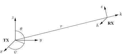
The transmitter (TX) is located in the origin of the (x, y, z) axis system (TX reference system). The receiver (RX) is located in P ≡ (r, θ, ψ) (spherical coordinates with respect to TX reference system) where the electric and magnetic fields are e(P, t) and h(P, t), respectively. Free-space propagation and far field (r > λ) conditions are satisfied. Thus e is orthogonal to h, both e and h are orthogonal to the propagation vector k, and ||e(P, t)|| is proportional to ||h(P, t)|| (Figure 7.1). A spherical coordinate system (r′, θ′, ψ′) with origin in the RX is also defined. Furthermore, in the case of both moving TX and RX, also a fixed reference system (r0, θ0, ψ0) will be considered.
Figure 7.1 Plane wave
The radiation pattern of the TX antenna αT(θ, ψ, fT) in the TX reference system is in general depending on the transmitted frequency fT. The radiation pattern of the RX antenna αR(θ′, ψ′, fR) in the RX reference system is in general depending on the received frequency fR. The presence of RX antenna only causes local modification in the electric and magnetic fields and does not affect the propagation delay r/c and the far-field attenuation factor 1/r.
7.1.2 Stationary TX, Stationary RX
Let us consider the propagation channel between a stationary TX and a stationary RX. For a complex sinewave transmitted signal at the TX antenna clamps xT(t) = ej2πft (TX frequency fT = f) the component of the electric field along the direction of e(P, t) in the RX location P is
(7.1) ![]()
where αT(θ, ψ, f) describes the TX radiation pattern. The received frequency is coincident with the transmitted frequency: fR = fT = f. The signal at the (possibly loaded) RX antenna clamps is given by
(7.2) ![]()
where
(7.3) ![]()
describes both TX and RX radiation patterns. More generally, α possibly includes also antenna-polarization and input-impedance mismatchs. Thus, the result is that
(7.4) ![]()
with
That is, the overall propagation channel is LTI with harmonic-response function H(f).
Let us consider now a generic (non sinusoidal) transmitted signal x(t) with Fourier transform X(f), that is,
(7.6) ![]()
Since Maxwell'equations are linear, for the superposition principle and accounting for (7.5), the signal at the RX antenna clamps is given by
where a(t), depending on θ, ψ, θ′, ψ′, is the inverse Fourier transform of α(θ, ψ, θ′, ψ′, f)/r and describes the linear distortion on the transmitted signal introduced by the TX and RX (frequency-dependent) radiation patterns.
Assumption 7.1.1 Wide-Band TX and RX Antennas (Stationary TX and RX). The overall TX and RX radiation pattern can be assumed to be constant with respect to frequency in the frequency interval where the spectral components of the transmitted (and hence also of the received) signal are relevant. That is, for some f0 it results that
(7.8) ![]()
Under the wide-band antenna assumption (Assumption 7.1), (7.7a)–(7.7c) specialize to
(7.9a) ![]()
(7.9b) ![]()
(7.9c) ![]()
That is, the propagation LTI channel introduces constant attenuation and delay:
(7.10) ![]()
7.1.3 Moving TX, Moving RX
Let both source (or transmitter (TX)) and observer (or receiver (RX)) be moving and let PT(u) and PR(t) be the three-dimensional vectors of TX and RX positions, respectively, with respect to a fixed reference system (r0, θ0, ψ0), where t is time measured at RX and u is time measured at TX.
Let t be the time at the receiver and D(t) the (time-varying) delay experienced by a transmitted wavefront before being received at time t. In other words, a wavefront transmitted at u = t − D(t) is received at time t. Consequently, the delay D(t) is due to the time-varying distance between TX located in P T(t − D(t)) and RX located in P R(t) (Kapoulitsas 1981; Neipp et al. 2003):
where c is the medium propagation speed and ||P|| is the norm of the vector P. In the considered fixed reference system (r0, θ0, ψ0), TX reference system (r, θ, ψ), and RX reference system (r′, θ′, ψ′) we have
(7.12) ![]()
(7.13) ![]()
(7.14) ![]()
(7.15) ![]()
The function ![]() (t, D(t)) is the time-varying distance covered by the wavefront transmitted at time t − D(t) in P
T(t − D(t)) and received at time t in P
R(t). It should not be confused with the time-varying distance between TX and RX at time t, that is, the distance between P
T(t) and P
R(t), which is
(t, D(t)) is the time-varying distance covered by the wavefront transmitted at time t − D(t) in P
T(t − D(t)) and received at time t in P
R(t). It should not be confused with the time-varying distance between TX and RX at time t, that is, the distance between P
T(t) and P
R(t), which is
Note that the time-varying distance ![]() (t, D(t)) (not R(t)) is responsible of the Doppler effect in the received signal. In fact, the time-varying delay D(t) is a consequence of the propagation from P
T(t − D(t)) to P
R(t) (see (7.11)) and not from P
T(t) to P
R(t). Even if R(t) is constant, we can still have Doppler effect if
(t, D(t)) (not R(t)) is responsible of the Doppler effect in the received signal. In fact, the time-varying delay D(t) is a consequence of the propagation from P
T(t − D(t)) to P
R(t) (see (7.11)) and not from P
T(t) to P
R(t). Even if R(t) is constant, we can still have Doppler effect if ![]() (t, D(t)), and hence D(t), are time-varying. For example, if both TX and RX move along two parallel lines with the same nonuniform motion law, R(t) is constant while
(t, D(t)), and hence D(t), are time-varying. For example, if both TX and RX move along two parallel lines with the same nonuniform motion law, R(t) is constant while ![]() (t, D(t)) is time-varying giving rise to Doppler effect. However, as shown in Sections 7.1.4 and 7.1.5, if either TX or RX is stationary, then
(t, D(t)) is time-varying giving rise to Doppler effect. However, as shown in Sections 7.1.4 and 7.1.5, if either TX or RX is stationary, then ![]() (t, D(t)) can be easily linked to R(t).
(t, D(t)) can be easily linked to R(t).
If the transmitted signal is a sinewave, the received signal is in turn a sinewave only if the propagation channel can be modeled as a (linear) FOT-deterministic time-variant system (Section 6.3.8 and (Izzo and Napolitano 2002a)). In all other cases, the received signal contains spectral components spread on a band depending on the time-varying nature of the propagation channel.
For a complex sinewave transmitted signal xT(t) = ![]() the component of the electric field along the direction of e(P
R(t), t) in the RX location P
R(t) at time t is due to transmission at time t − D(t) and is given by
the component of the electric field along the direction of e(P
R(t), t) in the RX location P
R(t) at time t is due to transmission at time t − D(t) and is given by
In general, this function is not sinusoidal. Its Fourier transform
(7.18) ![]()
depends on the RX position P
R(t) for t ![]() (− ∞ , + ∞). Each infinitesimal spectral component
(− ∞ , + ∞). Each infinitesimal spectral component
![]()
of the received electrical field gives rise to an infinitesimal voltage at the antenna clamps that depends on the time-varying RX radiation pattern
![]()
Since Maxwell's equations are linear, the overall received signal xR(t ; fT) corresponding to the transmitted complex sinewave xT(t) = ![]() is given by the superposition integral
is given by the superposition integral
Let us consider now a generic (non sinusoidal) transmitted signal x(t) with Fourier transform X(f), that is,
(7.20) ![]()
Since Maxwell's equations are linear, for the superposition principle the signal at the RX antenna clamps is given by
(7.21) 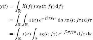
That is, the propagation channel is a LTV system (Section 1.1.7) with impulse-response function
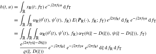
where, in the second and third equality, (7.17)–(7.19) are accounted for.
Assumption 7.1.2 Wide-Band TX and RX Antennas (Moving TX and RX). The overall TX and RX radiation pattern can be assumed to be constant with respect to frequency in the frequency interval where the spectral components of both the transmitted and received signals are relevant. That is,
(7.23) ![]()
where Y(fR) is the Fourier transform of y(t).
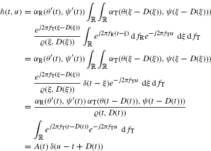
Under the wide-band antenna assumption (Assumption 7.1.2), the impulse-response function (7.22) of the propagation channel specializes into
where
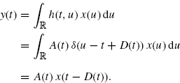
is the time-varying complex gain. Therefore, in the case of wide-band antennas the received signal is given by
Let us consider the transmitted signal
(7.27) ![]()
where Re{ · } denotes real part, fc is the carrier frequency, and ![]() is a complex signal which is coincident with the complex envelope provided that
is a complex signal which is coincident with the complex envelope provided that ![]() is an analytic signal, that is, the Fourier transform of
is an analytic signal, that is, the Fourier transform of ![]() is zero for negative frequencies (Gardner 1987b; Izzo and Napolitano 1997). According to (7.26), the received signal is given by
is zero for negative frequencies (Gardner 1987b; Izzo and Napolitano 1997). According to (7.26), the received signal is given by
where
(7.29) ![]()
That is, the complex signal ![]() can be obtained by a LTV transformation of the complex signal
can be obtained by a LTV transformation of the complex signal ![]() . The impulse-response function of the LTV system is
. The impulse-response function of the LTV system is
(7.30) ![]()
In a first approximation, the dependence on t in the gain A(t) can be neglected (Quinn and Hannan 2001, pp. 21–22) (see Assumption 7.3.1 and comments in Section 7.3.2). Thus, the impulse–response function of the LTV system can be written as
In Section 7.3, it is shown that in the special case of constant relative radial speed between TX and RX, the complex signal ![]() is obtained from
is obtained from ![]() by the LTV transformation with impulse-response function
by the LTV transformation with impulse-response function
which is obtained as a special case of (7.31). If s ![]() 1, then the LTV system can be approximated as linear periodically time-variant. If s
1, then the LTV system can be approximated as linear periodically time-variant. If s ![]() 1 and ν
1 and ν ![]() 0 then the LTV system can be approximated as LTI.
0 then the LTV system can be approximated as LTI.
Note that (7.32) is not the complex envelope of a real impulse-response function. In fact, even in the special case of LTI channel introducing just the complex gain a (s = 1, d0 = 0, and ν = 0), the complex envelope of the impulse-response function cannot obtained from (7.32) since it is given by
(7.33) ![]()
where fc is the carrier frequency of the real signal. On this subject, see also (Aiken 1967; Yoo 2008).
7.1.4 Stationary TX, Moving RX
Let be TX stationary and RX moving. That is, PT(u) = P
0 ∀ u ![]() R. Accordingly with (7.11) and (7.16) we have
R. Accordingly with (7.11) and (7.16) we have
and ![]() (t, D(t)) is independent of D(t). Equation (7.11) specializes into
(t, D(t)) is independent of D(t). Equation (7.11) specializes into
from which it follows that
where D.(t) denotes the first-order derivative of D(t) and R.(t) is the relative radial speed between P T(t) and P R(t).
7.1.5 Moving TX, Stationary RX
Let be TX moving and RX stationary. That is, P
R(t) = P
0 ∀ t ![]() R. Accordingly with (7.11) and (7.16) we have
R. Accordingly with (7.11) and (7.16) we have
and (7.11) specializes into
from which it follows that
(7.39) ![]()
and, hence,
7.1.6 Reflection on Point Scatterer
Let us consider a transmitted signal reflected on a point scatterer and then received. This is a model for radar/sonar systems where the scatterer is the target or for communications systems where the scatterer is a reflecting object in surroundings of transmitter or receiver. In radar systems also the clutter contribution should be accounted for and in some communications systems also the line-of-sight path should be considered. Such contributions are not considered here for the sake of simplicity and can be easily added in more realistic models. The equivalent system model is described in Figure 7.2, where
Figure 7.2 Reflection on point scatterer: transmitter TX, scatterer S, receiver RX

- x(t) is the transmitted signal;
- h1(t, u) is the impulse-response function of the propagation channel between transmitter and scatterer, which also includes the transmitter radiation pattern and the scatterer receiving radiation pattern;
- y1(t) is the signal received by the scatterer and retransmitted;
- h2(t, u) is the impulse-response function of the propagation channel between scatterer and receiver, which also includes the scatterer transmitting radiation pattern and the receiver radiation pattern;
- y2(t) is the received signal.
Let P T, P S, and P R be the three-dimensional vectors of positions of possibly moving transmitter (TX), scatterer (S), and receiver (RX), respectively. The scatterer is characterized by the radiation pattern αS(θS, ψS) to be considered in the receiving (θSR, ψSR) and retransmitting (θST, ψST) directions, with spherical coordinates taken in a reference system centered in the scatterer. Under the wide-band antenna assumption (Assumption 7.1.2), accounting for (7.11), (7.24), and (7.25), the LTV system describing the TX-S channel is
where D1(t) is the time-varying delay such that
(7.42) ![]()
and
(7.43) ![]()
is the time-varying complex gain introduced by the TX-S channel. Furthermore, the LTV system describing the S-RX channel is
where D2(t) is the time-varying delay such that
(7.45) ![]()
and
(7.46) 
is the time-varying complex gain introduced by the S-RX channel.
Let u, ts, and t, time measured at transmitter, scatterer, and receiver, respectively. From (7.41) it follows that a wavefront received at S at time ts is transmitted from TX at time
From (7.44) it follows that a wavefront received at RX at time t is transmitted from S at time
According to (7.26), the signal received from the scatterer and retransmitted is
(7.49) ![]()
and the signal at the receiver is
(7.50) 
Thus, the overall LTV system introduces a time-varying delay
which, accordingly with (7.47) and (7.48), is the overall delay experienced by a wavefront transmitted at
Moreover, the overall attenuation is
(7.53) ![]()
The radar cross-section (RCS) of the scatterer is
(7.54) ![]()
7.1.7 Stationary TX, Reflection on Point Moving Scatterer, Stationary RX (Stationary Bistatic Radar)
In a stationary bistatic radar system, both TX and RX are stationary and a reflection occurs on a moving target S located in P S (Figure 7.3). This case is obtained by specializing that in Section 7.1.6.
Figure 7.3 TX stationary, RX stationary, reflection on a moving scatterer S (stationary bistatic radar)
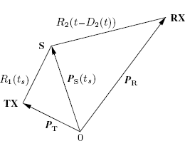
Let ts be the time at the moving scatterer S and D1(ts) the delay experienced by the transmitted wavefront before being received by the scatterer S at time ts. Let R1(ts) be the time-varying distance between the stationary TX and the moving scatterer S (first path). Define, analogously to (7.34),
(7.55) ![]()
According to (7.35) we have
(7.56) ![]()
Now, let t be the time at the stationary RX and D2(t) the delay experienced by the wavefront transmitted at time ts by the moving scatterer S before being received at time t. Due to (7.48), ts = t − D2(t). Let R2(t) be the time-varying distance between the moving scatterer S and the stationary RX (second path). Define, analogously to (7.37),
(7.57) ![]()
According to (7.38) we have
(7.58) ![]()
The overall delay D(t) experienced by a wavefront transmitted at t − D(t) by TX and received at time t by RX is given by (7.51) which specializes into
7.1.8 (Stationary) Monostatic Radar
By considering the special case of (7.59) when P T ≡ P R, we obtain the time-varying delay for the monostatic radar. In such a case, setting R1(t) = R2(t) = R(t) and D1(t) = D2(t) = D(t)/2 in (7.59) leads to
Equation (7.60) can be interpreted as follows. Let t be the time at the receiver and D(t) the delay experienced by the transmitted wavefront. The wavefront transmitted at t − D(t) is reflected by the target at t − D(t)/2. Consequently, the delay D(t) is due to the round-trip corresponding to the distance of the target from the monostatic stationary radar antenna at the time of reflection, that is at t − D(t)/2.
A more detailed analysis can be carried out accounting for boundary conditions for the electric and magnetic fields with relativistic correction on the target (Cooper 1980). In the special case of a plane wave scattered by a plane surface moving along the same direction of the propagation vector, the scattered waveform is amplitude modulated by a term proportional to (1 + R.(t)/c)/(1 − R.(t)/c) (Cooper 1980).
7.1.9 Moving TX, Reflection on a Stationary Scatterer, Moving RX
Let both TX and RX be moving, with a reflection occurring on a stationary scatterer S located in P S (Figure 7.4). This case is obtained by specializing that considered in Section 7.1.6 when both TX and RX are moving and the scatterer is stationary.
Figure 7.4 TX moving, RX moving, reflection on a stationary scatterer S
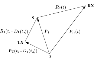
Let ts be the time at the stationary scatterer S and D1(ts) the delay experienced by the transmitted wavefront before being received by the scatterer S at time ts. Let R1(ts) be the time-varying distance between the moving TX and the stationary scatterer S (first path). Define, analogously to (7.37),
(7.61) ![]()
According to (7.38) we have
(7.62) ![]()
Now, let t be the time at RX and D2(t) the delay experienced by the wavefront transmitted at time ts by the scatterer S before being received at time t. Due to (7.48), ts = t − D2(t). Let R2(t) be the time-varying distance between the stationary scatterer S and the moving RX (second path). Define, analogously to (7.34),
(7.63) ![]()
According to (7.35) we have
(7.64) ![]()
The overall delay D(t) experienced by a wavefront received by RX at time t is given by (7.51)
Therefore,
(7.66) 
Due to (7.52), this results agrees with that in (Sadowsky and Kafedziski 1998).
The example considered in this section includes, as a special case, a synthetic aperture radar (SAR) observing a stationary scene. For a SAR, both TX and RX antennas move along the same direction and stay at the same distance provided that the speed of the aircraft is constant.


