7.3 Constant Relative Radial Speed
Let ξ(t) be the projection of the vector P R(t) − P T(t − D(t)) along the propagation direction ik (oriented from P T(t − D(t)) to P R(t)), that is
(7.77) ![]()
The delay D(t) experienced by the wavefront transmitted at time t − D(t) in P T(t − D(t)) and received at time t in P R(t) depends on the distance ||PR(t) − PT(t − D(t))||. Accordingly with (7.11) we have
As observed in Section 7.1.3, |ξ(t)| is the time-varying distance responsible of the Doppler effect, viz, the time-varying delay D(t), and should not be confused with
(7.79) ![]()
Let us assume that the relative radial speed between P T(t − D(t)) and P R(t) is constant within the observation interval. Thus, the projection of the vector P R(t) − P T(t − D(t)) along the propagation direction ik is a linear function of t. That is,
Furthermore, let us assume that, within the observation interval, RX does not collapse on TX. Thus, ξ(t) does not change sign and it is always ![]() (t, D(t)) > 0. Under such an assumption,
(t, D(t)) > 0. Under such an assumption, ![]() (t, D(t)) = ξ(t) or
(t, D(t)) = ξ(t) or ![]() (t, D(t)) = − ξ(t) is a linear function of time and the angles in TX and RX radiation patterns are constant with time:
(t, D(t)) = − ξ(t) is a linear function of time and the angles in TX and RX radiation patterns are constant with time:
(7.81) ![]()
7.3.1 Moving TX, Moving RX
The expression of D(t) depends on the sign of ξ(t). Specifically,
Therefore, from (7.80) we have (upper sign for ξ(t) ≥ 0 and lower sign for ξ(t) < 0)
(7.85) ![]()
and
(7.86) 
where
(7.88) ![]()
For a complex sinewave transmitted signal ![]() the component of the electric field along the direction of e(P
R(t), t) in the RX location P
R(t) at time t is
the component of the electric field along the direction of e(P
R(t), t) in the RX location P
R(t) at time t is
(7.89) 
where s is given in (7.87).
Assumption 7.3.1 It results that ![]() (observation interval). That is,
(observation interval). That is,
(7.90) ![]()
Thus, since (1 + x)α ![]() 1 + αx for |x|
1 + αx for |x| ![]() 1, the following approximation holds for the attenuation factor:
1, the following approximation holds for the attenuation factor:
(7.91) 
Note that a similar approximation cannot be made in the argument of the complex exponential ![]() since phases must be considered modulo 2π.
since phases must be considered modulo 2π.
![]()
That is, the attenuation factor equals a constant term 1/|ξ0| plus an amplitude modulating factor proportional to t − t0. The amplitude-modulation operator t, in the frequency domain, corresponds to the derivative operator d/df. Therefore, when ![]() , the approximation
, the approximation ![]() , ∀t
, ∀t ![]() [t0, t0 + T] consists in neglecting a small term which, in the frequency domain, is proportional to a T-finite approximation of δ(1)(f − sfT), the first-order derivative of the Dirac delta centered in sfT (Zemanian 1987, Section 1.3).
[t0, t0 + T] consists in neglecting a small term which, in the frequency domain, is proportional to a T-finite approximation of δ(1)(f − sfT), the first-order derivative of the Dirac delta centered in sfT (Zemanian 1987, Section 1.3).
Under Assumption 7.3.1 and making the approximation 1/|ξ(t)| ![]() 1/|ξ0| into the expression of e(P
R(t), t), the electric field at RX is a complex sinewave with frequency fR = sfT. Thus, the signal at the RX antenna clamps can be expressed in the following equivalent forms
1/|ξ0| into the expression of e(P
R(t), t), the electric field at RX is a complex sinewave with frequency fR = sfT. Thus, the signal at the RX antenna clamps can be expressed in the following equivalent forms
where
(7.93) ![]()
The transmitted frequency fT is transformed into the received frequency
(7.94) ![]()
where
(7.95) ![]()
is referred to as Doppler shift introduced by the time-varying channel.
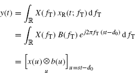
Let us consider a generic transmitted signal x(t) with Fourier transform X(f). Since Maxwell's equations are linear, starting from (7.92a) the signal at the RX antenna clamps can be expressed as
where b(t) is the inverse Fourier transform of B(fT). Equivalently, from (7.92b), we have
which compared with (4.82a) shows that the Doppler channel is a FOT-deterministic LTV system with the set Ω containing only one element σ and characterized by
(7.98) ![]()
(7.99) ![]()
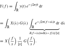
Moreover, by taking the Fourier transform of both sides of (7.97), we have
(7.100) 
Thus, accordingly with (4.81b), the FOT-LTV system can also be characterized by the functions
(7.101) ![]()
(7.102) ![]()
Under the wide-band TX and RX antenna assumption (Assumption 7.1.2), (7.96) specializes into
(7.103) ![]()
where
(7.104) ![]()
Thus, by considering the transmitted signal
(7.105) ![]()
where Re{ · } denotes real part and fc is the carrier frequency, the result is that
(7.106) 
where
with complex gain
(7.108) ![]()
and frequency shift
(7.109) ![]()
7.3.2 Stationary TX, Moving RX
In the case of stationary TX and moving RX, (7.11) specializes into (7.34) and (7.35). Assuming that during the observation interval RX does not collapse on TX, we have
From (7.80), (7.110), and (7.111), it follows
and comparing (7.80) and (7.112) it results in ![]() for ξ ≥ 0 and
for ξ ≥ 0 and ![]() for ξ < 0. In addition, (7.111) and (7.112) lead to
for ξ < 0. In addition, (7.111) and (7.112) lead to
The same expression can be obtained observing that, accounting for (7.112), (7.36) specializes into
(7.14) ![]()
The time-varying delay D(t) depends linearly on t: D(t) = d0 + d1t, with d0 ![]() (R0 − vt0)/c and
(R0 − vt0)/c and ![]() . Furthermore
. Furthermore
where
is the time-scale factor due to the time-varying delay.
For a complex sinewave transmitted signal ![]() the component of the electric field along the direction of e(P
R(t), t) in the RX location P
R(t) at time t is
the component of the electric field along the direction of e(P
R(t), t) in the RX location P
R(t) at time t is
(7.117) ![]()
where (7.17), (7.34), and (7.82) are accounted for. Thus, the electric field at RX is a sinewave with frequency ![]() amplitude-modulated by
amplitude-modulated by ![]() .
.
Under Assumption 7.3.1, ![]() , and
, and
(7.118) 
Under Assumption 7.3.1, and making the approximation ![]() , the electric field at RX is a sinewave with frequency fR = sfT. Thus, the signal at the RX antenna clamps is
, the electric field at RX is a sinewave with frequency fR = sfT. Thus, the signal at the RX antenna clamps is
where
(7.120) ![]()
The transmitted frequency fT is transformed into the received frequency
(7.121) ![]()
where
(7.122) ![]()
is the Doppler shift introduced by the time-varying channel. For s ≠ 1 the propagation channel is a FOT-deterministic LTV channel (Section 6.3.8), (Izzo and Napolitano 2002a).
For a transmitted frequency fT > 0, accounting for (7.112), we have:
- P
R(t) moves away from TX ⇒
 ⇒
⇒  ⇒ fR < fT
 - P
R(t) approaches TX ⇒
 ⇒
⇒  ⇒ fR > fT
Let us now consider a generic transmitted signal x(t) with Fourier transform X(f). Since Maxwell's equations are linear, by reasoning as for (7.96) the signal at the RX antenna clamps can be expressed as
where b(t) is the inverse Fourier transform of
(7.124) ![]()
which describes the filtering effect of the TX and RX antenna radiation patterns. Similarly to the case of moving TX and moving RX, the system with input/output relationship (7.123) can be expressed in terms of functions Gσ(λ), ϕσ(λ), Hσ(f), ψσ(f) that characterize FOT-deterministic LTV systems.
Under the wide-band TX and RX antenna assumption (Assumption 7.1.2), (7.123) specializes into
(7.125) ![]()
where
(7.126) ![]()
Thus, by considering the transmitted signal
(7.127) ![]()
where Re{ · } denotes real part and fc is the carrier frequency, and reasoning as for (7.107), the result is that
(7.128) ![]()
where
with complex gain
(7.130) ![]()
and frequency shift
7.3.3 Moving TX, Stationary RX
In the case of moving TX and stationary RX, (7.11) specializes into (7.37) and (7.38). Assuming that during the observation interval TX does not collapse on RX, we have
From (7.80), (7.132), and (7.133), it follows
(7.1134) ![]()
where the upper sign is for ξ(t) ≥ 0 and the lower for ξ(t) < 0. By substituting this expression of D(t) into (7.133) leads to
which implies that R(t) must be a linear function of t, say
where the strict inequality is consequence of the assumptions that within the observation interval TX does not collapse on RX. Substituting (7.136) into (7.135) we have
Since (7.137) holds for all t such that R(t − D(t)) > 0, it necessarily results
(7.138) ![]()
(7.139) ![]()
Therefore,
That is, the time-varying delay D(t) depends linearly on t: D(t) = d0 + d1t, with ![]() and
and ![]() . In addition, the time-varying distance R(t) between TX and RX is such that
. In addition, the time-varying distance R(t) between TX and RX is such that
(7.148) 
Furthermore
where
is the time-scale factor due to the time-varying delay.
Finally, note that the expression of D(t) in the rhs of (7.140) can be also obtained observing that, accounting for (7.136), (7.40) specializes into
(7.144) ![]()
For a complex sinewave transmitted signal ![]() the component of the electric field along the direction of e(P
R(t), t) in the RX location P
R(t) at time t is
the component of the electric field along the direction of e(P
R(t), t) in the RX location P
R(t) at time t is
(7.145) 
Thus, the electric field at RX is a sinewave with frequency ![]() amplitude-modulated by
amplitude-modulated by ![]() .
.
Under Assumption 7.3.1, that is |vT| < R0, and making the approximation ![]() , t
, t ![]() (t0, t0 + T), the electric field at RX is a sinewave with frequency fR = sfT. Thus, the signal at the RX antenna clamps is
(t0, t0 + T), the electric field at RX is a sinewave with frequency fR = sfT. Thus, the signal at the RX antenna clamps is
where
(7.147) ![]()
The transmitted frequency fT is transformed into the received frequency
(7.148) ![]()
where
(7.149) ![]()
is referred to as Doppler shift introduced by the time-varying channel. For s ≠ 1 the propagation channel is a FOT-deterministic LTV channel (Section 4.3.1), (Izzo and Napolitano 2002a).
For a transmitted frequency fT > 0, if P R(t) moves away from TX or approaches TX we have the same kind of order relationships between fR and fT as in the case of stationary TX and moving RX (Section 7.3.2).
Let us now consider a generic transmitted signal x(t) with Fourier transform X(f). Since Maxwell's equations are linear, by reasoning as for (7.96) the signal at the RX antenna clamps can be expressed as
where b(t) is the inverse Fourier transform of
(7.151) ![]()
which describes the filtering effect of the TX and RX antenna radiation patterns. Similarly to the case of moving TX and moving RX, the system with input/output relationship (7.150) can be expressed in terms of functions Gσ(λ), ϕσ(λ), Hσ(f), ψσ(f) that characterize FOT-deterministic LTV systems.
Under the wide-band TX and RX antenna assumption (Assumption 7.2), (7.150) specializes into
(7.152) ![]()
where
(7.153) ![]()
Thus, by considering the transmitted signal
(7.154) ![]()
where Re{ · } denotes real part and fc is the carrier frequency, and reasoning as for (7.107), the result is that
(7.155) ![]()
where
with complex gain
(7.157) ![]()
and frequency shift
Remark 7.3.2 The results of Section 7.1 are non-relativistic. For |R.(t)/c| < 1, the asymmetry in the results for stationary TX–moving RX and moving TX–stationary RX in the case of constant relative radial speed disappears.
In fact, for stationary TX–moving RX, from (7.116) and (7.131), one obtains
(7.159) ![]()
(7.160) ![]()
Furthermore, for moving TX–stationary RX, from (7.143) and (7.158) one has
(7.161) ![]()
(7.162) ![]()
where the approximate equalities hold for ![]() and the error is of the order of
and the error is of the order of ![]() .
.
7.3.4 Stationary TX, Reflection on a Moving Scatterer, Stationary RX (Stationary Bistatic Radar)
In this section, the combined Doppler effect in the case of stationary TX, reflection on a moving scatterer, and stationary RX is analyzed. This scenario corresponds to a stationary bistatic radar in the presence of a moving target. The propagation model is that described in Section 7.1.7 (see also Section 7.1.6 for notation).
Assumption 7.3.3 Both relative radial speeds of target with respect to TX (Radar 1) and RX (Radar 2) can be assumed to be constant within the observation interval.
Up link: From stationary TX (Radar 1) to moving RX (Target or Scatterer).
The propagation channel is characterized by
(7.163) ![]()
(7.164) ![]()
(7.165) ![]()
(7.166) ![]()
(7.167) ![]()
Let ![]() be the complex sinewave transmitted by radar 1. Under Assumptions 7.3 and 7.4, and according to (7.119), 1/R1(t)
be the complex sinewave transmitted by radar 1. Under Assumptions 7.3 and 7.4, and according to (7.119), 1/R1(t) ![]() 1/R01 and the signal received from the target is
1/R01 and the signal received from the target is
(7.168) ![]()
where (for t0 = 0)
Down link: From moving TX (Target or Scatterer) to stationary RX (Radar 2).
The propagation channel is characterized by
(7.170) ![]()
(7.171) ![]()
(7.172) ![]()
(7.173) ![]()
(7.174) ![]()
The complex sinewave transmitted by the target is ![]() . Under Assumptions 7.3 and 7.4, and according to (7.146), 1/R2(t)
. Under Assumptions 7.3 and 7.4, and according to (7.146), 1/R2(t) ![]() 1/R02 and the signal at the RX antenna clamps is
1/R02 and the signal at the RX antenna clamps is
(7.175) ![]()
where (for t0 = 0)
The overall time-scale factor is
The transmitted frequency fT is transformed into the received frequency
(7.78) ![]()
where
(7.179) ![]()
is the Doppler shift introduced by the overall (TX-S-RX) time-varying channel.
Let us consider a generic transmitted signal x(t) with Fourier transform X(f). Since Maxwell's equations are linear, the signal at the RX antenna clamps is
Under Assumption 7.1.2 on TX and RX radar antennas and modeling the target as a RX and TX antenna satisfying Assumption 7.1.2, (7.169) and (7.176) (for t0 = 0) reduce to
(7.181) ![]()
(7.182) ![]()
with![]() , and (7.180) specializes into
, and (7.180) specializes into
(7.183) 
with a ![]() α1α2, s given by (7.177), and
α1α2, s given by (7.177), and
(7.184) ![]()
7.3.5 (Stationary) Monostatic Radar
For a stationary monostatic radar TX and RX antennas are coincident. Thus, the analysis is made by specializing the results for the bistatic radar to the case R1(t) = R2(t). It follows that ![]() , R01 = R02 = R0, and
, R01 = R02 = R0, and
(7.185) ![]()
(7.186) ![]()
(7.187) ![]()
7.3.6 Moving TX, Reflection on a Stationary Scatterer, Moving RX
In this section, the combined Doppler effect in the case of moving TX, reflection on a stationary scatterer S, and moving RX is analyzed. If TX and RX move along the same direction and stay always at the same distance, this scenario corresponds to a SAR illuminating a stationary scene. The propagation model is that described in Section 7.1.9.
If both the relative radial speeds between TX and S and between S and RX are constant within the observation interval, then
(7.188) ![]()
In the first path (moving TX, stationary receiver S), for all values of ts such that
![]()
that is, since ts = t − D2(t), for all values of t such that
![]()
accounting for (7.140), we have
(7.189) ![]()
In the second path (stationary transmitter S, moving RX) for all values of t such that
![]()
accounting for (7.113), we have
(7.190) ![]()
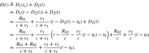
Thus, the expression of the overall delay D(t) in (7.65) specializes into
(7.191) 
7.3.7 Non-synchronized TX and RX oscillators
The received signal models (7.129) and (7.156) can also account for possible frequency and phase mismatch, νosc and ϕosc, respectively, of the local (RX) oscillator with respect to the transmitter oscillator. In such a case, it results that
(7.192) ![]()
and the overall frequency shift ν + νosc = (s − 1)fc + νosc is not proportional to fc only through the factor (s − 1).


