
21
Fingerprint Scanner
In this project we’ll use a fingerprint sensor, a servomotor, and some LEDs to create a cool biometric entry system.

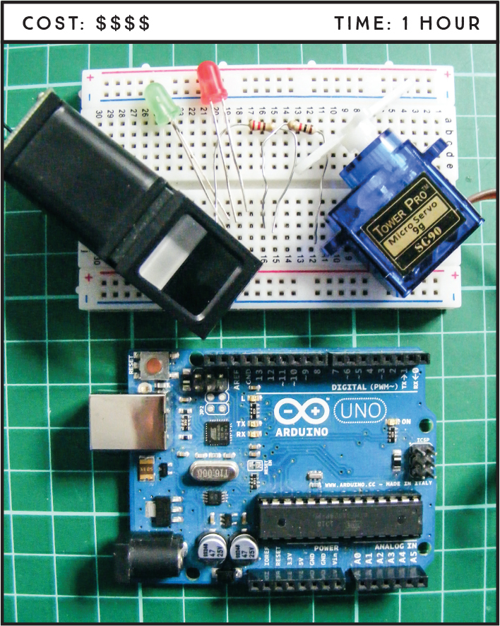
PARTS REQUIRED
Arduino board
Breadboard
Jumper wires
Red LED
Green LED
2 220-ohm resistors
Tower Pro SG90 9g servomotor
Optical fingerprint sensor (ZFM-20 Series)
LIBRARIES REQUIRED
Adafruit_Fingerprint
Servo
SoftwareSerial
NOTE
The software we’re using in this project operates only on Windows.
HOW IT WORKS
Biometric identification is used to identify a person from a specific biological characteristic that remains the same even over a long period of time, such as a fingerprint or iris pattern. Since fingerprints are unique to each person, they’re often used to help identify individuals for purposes like criminal investigations and security authentication. In this project, we’ll use a fingerprint sensor to read a fingerprint and, if it matches a print on record with the right security clearance, allow access by moving a servomotor.
The sensor we’ll use is the ZFM-20 Series Fingerprint Identification Module (see Figure 21-1) but will generally be referred to as an optical fingerprint sensor module. The sensor takes a photograph of a fingerprint, adds it to the module’s database, and then checks the scanned fingerprint for a match. It can hold up to 162 fingerprints. The sensor is available online and from retailers such as Adafruit, which has also created a specific Arduino library for the module that we’ll use in the sketch.
FIGURE 21-1: The ZFM-20 Series Fingerprint Identification Module is an optical fingerprint sensor.

PREPARING THE FINGERPRINT SENSOR
To use the sensor, we must first get the SFG Demo software, available to download from http://www.adafruit.com/datasheets/SFGDemoV2.0.rar. The SFG Demo software is a simple, free program that connects your PC to the Fingerprint ID module via an Arduino so you can control it, add or delete fingerprints, and assign an ID for each one.
Download the SFGDemoV2.0.rar file and unzip to a destination of your choice.
Once you have unzipped the .rar file, double-click the SFGDemo.exe file to run the program, and you’ll see the screen shown in Figure 21-2.
FIGURE 21-2: The SFGDemo control screen

Now you need to connect the fingerprint sensor module to your PC via the Arduino. The connections for the module to Arduino are shown in the following table.
FINGERPRINT SENSOR
ARDUINO
GND (black wire)
+5V
RX (white wire)
Pin 0 (RX)
TX (green wire)
Pin 1 (TX)
+5V (red wire)
+5V
You’ll be using the Arduino as a bypass to connect the fingerprint scanner to your PC via the USB cable, so you need to load a blank sketch to get the Arduino to connect to the PC without carrying out a function. The easiest way to do this is to open the latest version of the Arduino IDE and upload the default sketch, shown next.
void setup() {
// put your setup code here, to run once:
}
void loop() {
// put your main code here, to run repeatedly:
}Next, connect the Arduino to your PC and in the SFGDemo program, select the Open Device button. From the Com Port drop-down menu that opens, choose the port your Arduino is connected to and click OK. You’ll see a message indicating that your module is connected and recognized, as shown in Figure 21-3. Here my module is connected to the Arduino through com port 4, but you might need to use a different port.
FIGURE 21-3: When the device is connected correctly, the program shows the message “Open Device Success!”

Next, you’ll add a fingerprint to the database. Click Enroll on the SFGDemo control screen. When you see the message “Waiting for fingerprint,” press a finger firmly against the fingerprint sensor module window and wait a few seconds. When the print is registered, you’ll see the message “Success!” (as shown in Figure 21-4).
FIGURE 21-4: The module has successfully captured a fingerprint and shows a preview of the print in the top-left window.

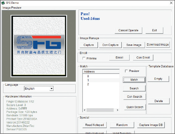
Now you’ll test whether the module recognizes the fingerprint you just recorded. Click the Match button on the SFGDemo control screen. When prompted, press your finger against the window firmly for a few seconds. If the demo finds a match, you’ll see the “Pass!” message shown in Figure 21-5.
FIGURE 21-5: The fingerprint matches and a “Pass!” message displays in the information panel of the SFGDemo control panel.
Now you need to check that the module recognizes your fingerprint when it’s attached to the Arduino and not the PC. Close the SFGDemo program and, from the resources you downloaded from https://www.nostarch.com/arduinohandbook2/, add the Adafruit Fingerprint Sensor library to your IDE. If you need a refresher on adding libraries, check out the library section at the start of this book.
Once you’ve added the Adafruit Fingerprint Sensor library, open the IDE and select Files ▸ Examples ▸ Adafruit-fingerprint-sensor-master ▸ Fingerprint to choose the library fingerprint sketch shown in Figure 21-6. Upload this sketch to your Arduino.
FIGURE 21-6: The fingerprint demo sketch from the Adafruit Fingerprint Sensor library

NOTE
Your sensor may come with six wires, two of which aren’t necessary for the demo.
Once you’ve uploaded the fingerprint sketch to your Arduino, disconnect from the PC. You now need to change your module/ Arduino pin setup. Instead of connecting the module to the TX and RX pins, change these connections to pins 2 and 3 on the Arduino, respectively, as shown in the following table. This keeps the TX and RX serial communication free to use the Arduino IDE Serial Monitor in the next step.
FINGERPRINT SENSOR
ARDUINO
GND (black wire)
+5V
TX (green wire)
Pin 2
RX (white wire)
Pin 3
+5V (red wire)
+5V
Now, reconnect your Arduino to the PC and open the Arduino IDE. Open the Serial Monitor of the IDE. When you press your finger to the module window, you should see something like Figure 21-7.
FIGURE 21-7: The module processes are displayed in the Arduino IDE serial screen.

THE BUILD
Now that you know the module is working as expected, you’ll use what you’ve learned to create the fingerprint entry system.
The fingerprint module should now be connected to the Arduino, but if you’re starting at this point, follow the connections given in step 10 before proceeding.
Connect the servomotor to the GND and +5V power rails on the breadboard and connect the signal pin to Arduino pin 9, as shown in the following table.
SERVO
ARDUINO
Signal (yellow wire)
Pin 9
Positive power (red wire)
Breadboard +5V rail
Negative power (black wire)
Breadboard GND rail
Insert the LEDs into the breadboard so that the shorter, negative leg is connected to the GND power rail of the breadboard and the positive, longer leg is connected to Arduino pins 7 and 8 via a 220-ohm resistor, as shown in the following table. The resistors should straddle the center of the breadboard, as shown in Figure 21-8.
LEDS
ARDUINO
Green LED (positive, longer leg)
Pin 7 via 220-ohm resistor
Red LED (positive, longer leg)
Pin 8 via 220-ohm resistor
Negative power of both LEDs (shorter leg)
Breadboard GND rail
FIGURE 21-8: The LEDs are connected to the Arduino pins via 220-ohm resistors.

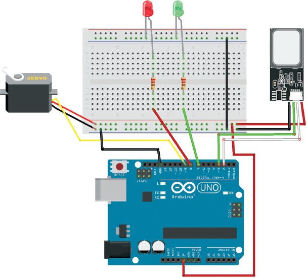
Connect the power rails of the breadboard to +5V and GND on the Arduino, and then check that your circuit matches Figure 21-9.
Upload the code in “The Sketch” on page 183.
FIGURE 21-9: The circuit diagram for the fingerprint scanner
THE SKETCH
The sketch first calls on the Servo, SoftwareSerial, and Adafruit_ Fingerprint libraries. The LED and servo pins are defined as 7, 8, and 9, respectively, and pins 2 and 3 are defined for serial connection to the fingerprint sensor module. The fingerprint library handles the functionality of the module, and the sketch has a series of steps to read and store a fingerprint.
The sensor automatically scans every 5 seconds and reads the fingerprint when it is pressed to the window. If the fingerprint matches one in the module memory (which we stored earlier in the project), the red LED will turn off, the green LED will light, and the servomotor will turn 180 degrees. This state will continue for 5 seconds, and the setup will reset and wait for another valid entry.
// Fingerprint Sensor Library reproduced with kind permission
// from Adafruit Industries
/***************************************************
This is an example sketch for our optical Fingerprint sensor
Designed specifically to work with the Adafruit BMP085 Breakout
----> http://www.adafruit.com/products/751
These displays use TTL Serial to communicate, 2 pins are required to
interface
Adafruit invests time and resources providing this open source code,
please support Adafruit and open-source hardware by purchasing
products from Adafruit!
Written by Limor Fried/Ladyada for Adafruit Industries.
BSD license, all text above must be included in any redistribution
****************************************************/
#include <Servo.h>
#include <Adafruit_Fingerprint.h>
#if ARDUINO >= 100
#include <SoftwareSerial.h>
#else
#include <NewSoftSerial.h>
#endif
int getFingerprintIDez();
int ledaccess = 7; // Green LED pin
int leddeny = 8; // Red LED pin
int servoPin = 9; // Servo pin
Servo doorLock;
// Pin #2 is IN from sensor (GREEN wire)
// Pin #3 is OUT from arduino (WHITE wire)
#if ARDUINO >= 100
SoftwareSerial mySerial(2, 3); // Pins for the fingerprint sensor
#else
NewSoftSerial mySerial(2, 3);
#endif
Adafruit_Fingerprint finger = Adafruit_Fingerprint(&mySerial);
void setup() {
doorLock.attach(servoPin); // We define the servo pin
pinMode(ledaccess, OUTPUT); // Green LED pin set as an ouput
pinMode(leddeny, OUTPUT); // Red LED pin set as an output
pinMode(servoPin, OUTPUT); // Servo pin set as an output
Serial.begin(9600); // Start sending messages to the Serial Monitor
Serial.println("fingertest");
finger.begin(57600); // Set data rate for the sensor serial port
// Start the module and checking for fingerprint
if (finger.verifyPassword()) {
Serial.println("Found fingerprint sensor!");
} else {
Serial.println("Did not find fingerprint sensor :(");
while (1);
}
Serial.println("Waiting for valid finger...");
}
void loop() {
int ID = getFingerprintIDez(); // Get the fingerprint ID#
// Reset the device to the test state
digitalWrite(ledaccess, HIGH);
digitalWrite(leddeny, HIGH);
doorLock.write(0);
if (ID >= 0) { // Valid ID. Unlocked state
// Enable the access LED, turn off the deny LED
digitalWrite(ledaccess, HIGH);
digitalWrite(leddeny, LOW);
// Unlock the servo
doorLock.write(180);
}
else if (ID == -3) { // ID doesn't match any registed print
// Locked state
// Enable the deny LED, turn off the access LED
digitalWrite(ledaccess, LOW);
digitalWrite(leddeny, HIGH);
}
delay(5000);
}
uint8_t getFingerprintID() {
uint8_t p = finger.getImage();
switch (p) {
case FINGERPRINT_OK: // Sensor takes a photo when a finger is
// placed on the module window
Serial.println("Image taken");
break;
case FINGERPRINT_NOFINGER:
Serial.println("No finger detected");
return p;
case FINGERPRINT_PACKETRECIEVEERR:
Serial.println("Communication error");
return p;
case FINGERPRINT_IMAGEFAIL:
Serial.println("Imaging error");
return p;
default:
Serial.println("Unknown error");
return p;
}
p = finger.image2Tz(); // OK success! We have a fingerprint and
// now check that it can be read
switch (p) {
case FINGERPRINT_OK:
Serial.println("Image converted");
break;
case FINGERPRINT_IMAGEMESS:
Serial.println("Image too messy");
return p;
case FINGERPRINT_PACKETRECIEVEERR:
Serial.println("Communication error");
return p;
case FINGERPRINT_FEATUREFAIL:
Serial.println("Could not find fingerprint features");
return p;
case FINGERPRINT_INVALIDIMAGE:
Serial.println("Could not find fingerprint features");
return p;
default:
Serial.println("Unknown error");
return p;
}
p = finger.fingerFastSearch(); // OK converted! It's valid, so
// check it against module memory
if (p == FINGERPRINT_OK) {
Serial.println("Found a print match!");
} else if (p == FINGERPRINT_PACKETRECIEVEERR) {
Serial.println("Communication error");
return p;
} else if (p == FINGERPRINT_NOTFOUND) {
Serial.println("Did not find a match"); // No match found,
// back to the start
return p;
} else {
Serial.println("Unknown error");
return p;
}
// We found a match! So the following will run:
Serial.print("Found ID #"); Serial.print(finger.fingerID);
Serial.print(" with confidence of "); Serial.println(finger.confidence);
return finger.fingerID;
}
// Returns -1 if failed, otherwise returns ID #
int getFingerprintIDez() {
int p = finger.getImage();
if (p != FINGERPRINT_OK) return -1;
p = finger.image2Tz();
if (p != FINGERPRINT_OK) return -2;
p = finger.fingerFastSearch();
if (p != FINGERPRINT_OK) ; {
Serial.println("No match found");
return -3;
}
// Found a match!
Serial.print("Found ID #"); Serial.print(finger.fingerID);
Serial.print(" with confidence of "); Serial.println(finger.confidence);
return finger.fingerID;
}
TROUBLESHOOTING
Q. The code compiles, but the fingerprint sensor does not light up or function.
• Make sure that your wiring matches the tables on page 181 and page 182. This code will work only with the fingerprint sensor I’ve used in this project.
• If your sensor has six wires instead of the expected four and the wire colors don’t match as described, it is the first four pins you need: GND, TX, RX, and +5V. The other two connections are not used in this project, so you can remove these wires.
• If your module still does not light up, check the data sheet for the actual pin configuration and reconnect the wires according to that.
• Remember you need to set up the module first and test it as described in “Preparing the Fingerprint Sensor” on page 176.
Q. The LEDs do not light up as expected.
• Ensure the LEDs are firmly inserted into the breadboard and the resistors line up with the connections to the Arduino.
• Remember to connect power to the breadboard rails.
Q. The servomotor does not move as expected.
• Double-check that the wiring matches the servo connections shown in Figure 21-9.
• The module, servo, and LEDs combined draw a fair amount of power from your battery pack, and while the Arduino can still function at a lower voltage, the servomotor cannot. Change to fresh batteries.