
Now that we know how to control a motor and its direction of rotation, let's have a look at controlling the speed of a motor, which is necessary for advanced maneuvering.
The speed control happens through the PWM technique, where we vary the width of pulses to control the speed.
This technique is used to get analog results by digital means. The digital pins on the Intel Edison produce a square wave:

The on and off pattern can simulate voltages between a full on 5V and a full off 0V. This is manipulated by altering the time the signal spends on and the time the signal spends off. The duration of the on time is called pulse width. In order for us to get varying pulse values, we change or modulate the pulse width. If this is done fast enough, then the result is a value between 0-5V.
There are PWM pins on the Arduino breakout board for the Intel Edison. These pins are used:

Now we can implement this to control the speed of our own motors. In the preceding L293D IC, the enable pins can be used for PWM input.
Modules of L293D mainly expose the following pins:
- Input 1 for motor 1
- Input 2 for motor 1
- Input 1 for motor 2
- Input 2 for motor 2
- Enable for motor 1
- Enable for motor 2
- Vcc
- Gnd
Take a look at the following module:
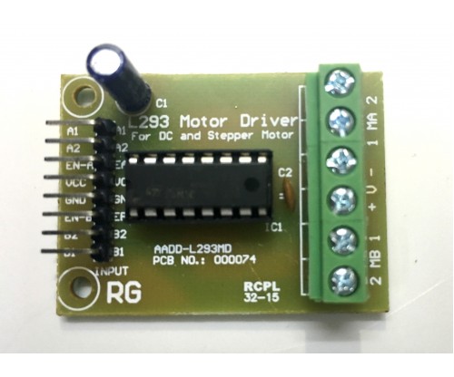
A total of eight pins are exposed, as mentioned previously.
Connect the enable pins to any of the PWM pins on the Intel Edison:
- Enable 1 to digital pin 6
- Enable 2 to digital pin 9
Next, to control the speed we need to use the analogWrite method in those enabled PWM pins on the Intel Edison.
To set the frequency of the Intel Edison's PWM control, use the example shown in the following link and clone it:
https://github.com/MakersTeam/Edison/blob/master/Arduino-Examples/setPWM_Edison.ino
The range of values of the analogWrite method is 0-255, where 0 is always off and 255 is always on.
Now using this modify the preceding code to set the enable pin values. An example of using it is shown here. The task of controlling the pins in a fully-fledged motion is left to the reader:
#define M11 2
#define M12 3
#define M21 4
#define M22 5
#define PWM 6
void setup()
  {
    pinMode(M11,OUTPUT);
    pinMode(M12,OUTPUT);
    pinMode(M21,OUTPUT);
    pinMode(M22,OUTPUT);
  }
void loop()
  {
    forward();
  }
void forward()
  {
    digitalWrite(M11,HIGH);
    digitalWrite(M12,LOW);
    digitalWrite(M21,HIGH);
    digitalWrite(M22,LOW);
    analogWrite(PWM, 122);
  }
In the preceding code, stress on the forward method, where we've used analogWrite (PWM, 122). This means that the motor should now rotate half of its original speed. This technique can be used for faster line following robots and speed control.