
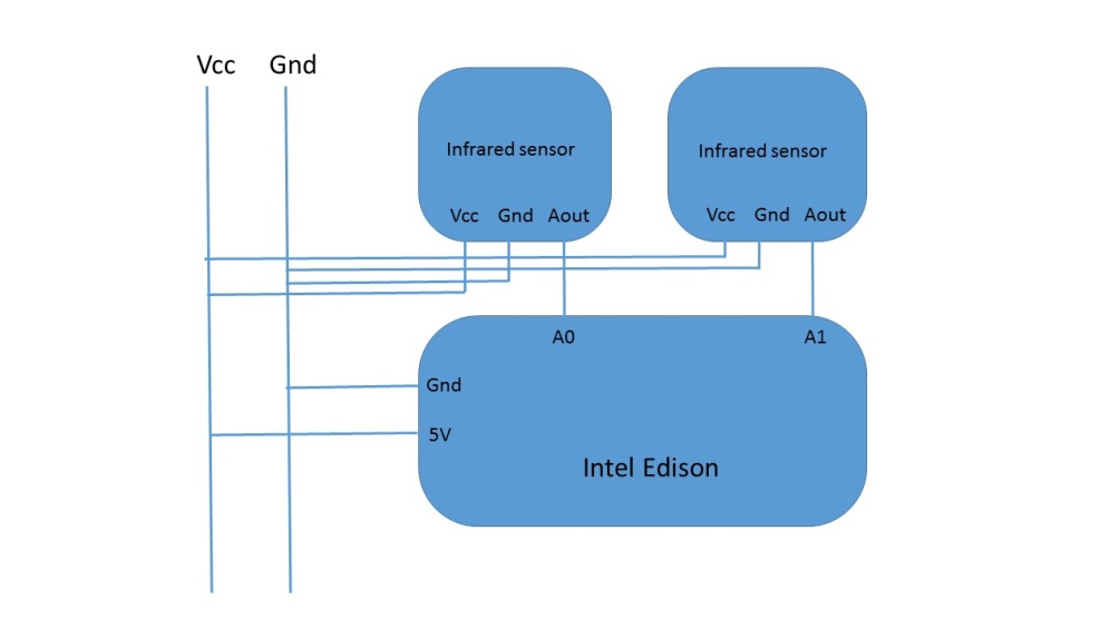
Follow the following circuit diagram for the hardware setup:
Sensor calibration circuit
The circuit is pretty straightforward and simple to understand. Just attach two sensors to the A0 and A1 pins and the common Vcc and Gnd connections.
Now, let's get on with the code:
void setup()
  {
    Serial.begin(9600);
  }
void loop()
  {
    int a= analogRead(A0);
    int b= analogRead(A1);
    Serial.print(a);
    Serial.print("       ");
    Serial.println(b);
    delay(200);
  }
The preceding code returns us the values and readings from both the sensors. After you burn the code into the Intel Edison, you will start receiving the values from the sensors. Now, it is required to perform the tests as mentioned in calibration to calibrate the sensors.