
L293D is a typical motor driver integrated circuit that can drive two motors in both directions. It's like a starter for every robotics project. It's a 16-bit IC:

The maximum voltage for Vs motor supply is 36V. It can supply a max current of 600mA per channel.
It works on the concept of H bridge. The circuit allows the flow of current in either direction. Let's have a look at the H bridge circuit first:
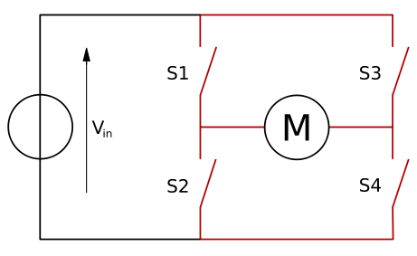
Here, S1, S2, S3, and S4 are switches that in real life contain transistors. The operation is extremely simple. When S1 and S4 are on, the central motor rotates in one direction while the reverse happens when S2 and S3 are on. S1, S2, S3, and S4 receive control signals from the microcontroller and operate the direction of the motor accordingly.
The L293D consists of two such circuits. Thus, we can control up to two motors. One can use the L293D as a module or just as a standalone IC. Normally what we need to worry about are four pins, where we'll send control signals. We have the pin layout for L293D. Let's have a look at what signals will result in what kind of action.
Pins 1-8 are responsible for one motor, while pins 9-16 are responsible for the other.
Enable pin is set to logic high for the operation. The same goes for the other side.
What needs to be tampered with are the input pins 2, 7, 10, and 15. The motors are connected to pins 3, 6, 11, and 14. Vss is for the power supply for the motor, while Vss or Vcc is for the internal power supply. While enable 1 and enable 2, that is pins 1 and 9, are set to high depending on the condition:
|
Pin 2 or 10 |
Pin 7 or 15 |
Motor |
|
High |
Low |
Clockwise |
|
High |
High |
Stop |
|
Low |
Low |
Stop |
|
Low |
High |
Anti-clockwise |
The preceding table summarizes the action triggered based on the input. It is to be noticed that if both the input pins are either on or off then the motor won't rotate. Now in typical L293D modules, only four control pins are exposed and the main voltage supply and Gnd pins are exposed. In the preceding table, it is mentioned as 2 or 10 and 7 or 15. The pair goes as 2 and 7 or 10 and 15. It means that 2 is on or 10 is off and the same goes for the other as well. The motion of the motor, which is designated as clockwise and anti-clockwise, depends on the connection of the motor. Assume that the rotation direction reverses when the control signal changes.