
The name might be a bit fancy but this UGV is quite simple with the only difference being that it contained four high torque motors powered by a single dual driver motor driver circuit. Initially, we used two driver circuits but then we shifted to one. It was powered by a Li-Po battery but all tests were conducted using an SMPS. The UGV was controlled by a WPF application with the name of universal remote controller. This UGV was also fitted with a camera with an operating frequency of 5.8 GHz. The UGV was also wireless using a 2.4 GHz RF module. Let's have a look at the hardware required apart from the Intel Edison:
- 30 cm by 30 cm chassis(1)
- 10 cm diameter wheels(4)
- High torque motors 300 RPM 12V(4)
- 20A dual motor driver(1)
- RF 2.4 GHz USB link(1)
- RF 2.4 GHz Serial link(1)
- Li-Po battery (minimum voltage supply: 12V; maximum current drawn: 3-4A)
This section will cover the hardware aspect of it and how to develop the controller application using WPF. The chassis combined with the wheels falls under the deign principle discussed in preceding figure. Let's have a look at the circuit diagram of the UGV. If the robot is made using the earlier mentioned hardware, then the robot will perform well in rough terrain and also be able to climb a steep slope of 60-65 degrees (tested):
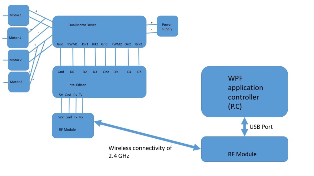
Motor 1 represents the left hand side motors while motor 2 represents the right hand side motors. Both the left hand side motors are shorted and same goes for the left hand side motors as well. This particular UGV was programmed to receive certain characters through serial port communication and provide some action based on that. Now, let's have a look at the code of the Intel Edison:
#define SLOW_SPEED 165
#define MAX_SPEED 255
int pwm1=6,dir1=2,brk1=3,pwm2=9,dir2=4,brk2=5;
void setup()
{
Serial1.begin(9600);
  pinMode(2,OUTPUT);
  pinMode(6,OUTPUT);
  pinMode(3,OUTPUT);
  pinMode(4,OUTPUT);
  pinMode(5,OUTPUT);
  pinMode(9,OUTPUT);
}
/*
         * 1: Fast front
         * 0: Fast back
         * 3: Fast right
         * 4: Fast left
         * 5: STOP
         * 6: Slow front
         * 7: Slow back
         * 8: Slow right
         * 9: Slow left
         * */
void loop()
{
  if(Serial1.available()>0)
  {
    char c= Serial1.read();
    if(c=='1')
    forward(MAX_SPEED);
    else if(c=='0')
    backward(MAX_SPEED);
    else if(c=='3')
    right(MAX_SPEED);
    else if(c=='4')
    left(MAX_SPEED);
    else if(c=='6')
    forward(SLOW_SPEED);
    else if(c=='7')
    backward(SLOW_SPEED);
    else if(c=='8')
    right(SLOW_SPEED);
    else if(c=='9')
    left(SLOW_SPEED);
    else if(c=='5')
    stop();
  }
}
void forward(int speed)
{
  //Left side motors
  digitalWrite(2,LOW); //Direction
  digitalWrite(3,LOW); //Brake
  analogWrite(6,speed);
  //Right side motor
  digitalWrite(4,LOW); //Direction
  digitalWrite(5,LOW); //Brake
  analogWrite(9,speed);
}
void backward(int speed)
{
  //Left side motors
  digitalWrite(2,HIGH);//Direction
  digitalWrite(3,LOW); //Brake
  analogWrite(6,speed);
  //Right side motor
  digitalWrite(4,HIGH);//Direction
  digitalWrite(5,LOW); //Brake
  analogWrite(9,speed);
}
void left(int speed)
{
  //Left side motors
  digitalWrite(2,LOW);//Direction
  digitalWrite(3,LOW); //Brake
  analogWrite(6,speed);
  //Right side motor
  digitalWrite(4,HIGH);//Direction
  digitalWrite(5,LOW); //Brake
  analogWrite(9,speed);
}
void right(int speed)
{
  //Left side motors
  digitalWrite(2,HIGH);//Direction
  digitalWrite(3,LOW); //Brake
  analogWrite(6,speed);
  //Right side motor
  digitalWrite(4,LOW);//Direction
  digitalWrite(5,LOW); //Brake
  analogWrite(9,speed);
}
void stop()
{
  //Left side motors
  digitalWrite(2,LOW);//Direction
  digitalWrite(3,HIGH); //Brake
  analogWrite(6,122);
  //Right side motor
  digitalWrite(4,LOW);//Direction
  digitalWrite(5,HIGH); //Brake
  analogWrite(9,122);
}
The preceding code executes functions based on the data received. The following table summarises the characters responsible for the data received:
|
Character Received |
Action Undertaken |
|
0 |
Fast back |
|
1 |
Fast front |
|
3 |
Fast right |
|
4 |
Fast left |
|
5 |
Stop |
|
6 |
Slow front |
|
7 |
Slow back |
|
8 |
Slow right |
|
9 |
Slow left |
We have created two macros for max and slow speed. The parameters for methods of motion execution is the speed that is passed based on the data received. You can test it using your serial monitor. Now, that we have the hardware lets write a software for it. This software will be able to control the robot using keyboard as well.