
When we are dealing with electrical load, we simply cannot directly connect it to Edison or any other boards, as it will end up frying. For dealing with these loads, an interfacing circuit is used called a relay. A relay in its crude form is a series of electromechanical switches. They operate on a DC voltage and control AC sources. Components that will be used are listed as follows:
- Intel Edison
- 5V relay module
- Electric bulb wires
Before going into the circuitry, we'll discuss relays first:

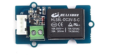
The red rectangular area represents the electromagnet. We excite the electromagnet with a DC voltage, and that triggers the mechanical switch. Having a closer look at the preceding image, we can see three ports where the AC load is connected: common, normally closed, and normally open. In default conditions, that is when the electromagnet is not excited, and the common and normally closed ports are connected. What we are interested in for now is the normally open port.
The image of the relay used is shown as follows:
The electrical load will have a live and neutral wire. Connect either one according to the following circuit:

With reference to the preceding figure, Vcc and Gnd are connected to the controller. The AC source connects one end of the electrical load directly, while the other is via the relay. A part of it connects the common port, while the other may be in normally closed (NC) or normally open (NO). When you have the other end of the electrical load connected to the NC port, then by default without excitation of the electromagnet, the circuit is complete. Since we don't want the bulb to be operating when the electromagnet isn't excited, connect it to the NO port, rather than NC. Thus, when the electromagnet is operating by applying voltage on Vcc and Gnd as ground, the mechanical switch flips to the NO position, thus connecting it with the common port.
The whole idea behind the operation of a relay is the use of electromechanical switches to complete a circuit. However, it is worth noting that not all relays operate on the same principle; some relays use solid state devices to operate.
Solid State Relays (SSRs) don't have any movable parts unlike that of electromechanical relays. SSRs uses photo-couplers to isolate the input and the output. They change electrical signals to optical signals, which propagates through space and thus isolates the entire circuit. The coupler on the receiving end is connected to any switching device, such as a MOSFET, to perform the switching action.
There are some advantages of using SSRs over electromechanical relays. They are as follows:
- They provide high speed, high frequency switching operations
- There is failure of contact points
- They generate minimal noise
- They don't generate operation noise
Although we will use electromechanical relays for now, if the use case deals with high frequency switching, then it's better to go with SSRs. It is also to be noted that when exposed to long usage, SSRs are known to heat up.