
The list of hardware required for a simple two-wheel drive line follower robot is as follows:
- Robot chassis
- 9V DC motors
- Motor driver L293D
- Two infrared sensors
- 9V DC power supply
- Two wheels
- One castor
- Intel Edison, which is used as a controller
The process of attaching the motors to the chassis and the castor won't be shown. A circuit diagram will be shown, and arranging all the components depends on the reader.
Use a two or a four-wheel drive robot chassis, and as we are using two wheels we will fit the castor on the front of the robot. The the sensors should be at the front, on either side of the robot. Let's consider a 2D model of our robot:

The preceding figure is a 2D model of the line follower robot with 2WD. The sensors should be on either side and the castor in the middle. While the L293D and the Intel Edison can be located anywhere, the position of the castor, sensors, motors, and obviously the wheels should be the same or similar to the structure shown in the preceding figure.
The hardware setup usually takes a bit of time as it involves a lot of tickling of wires and loose soldering joints usually add in more problems. Now, before moving forward with the code, let's wire everything up with the following circuit diagram:
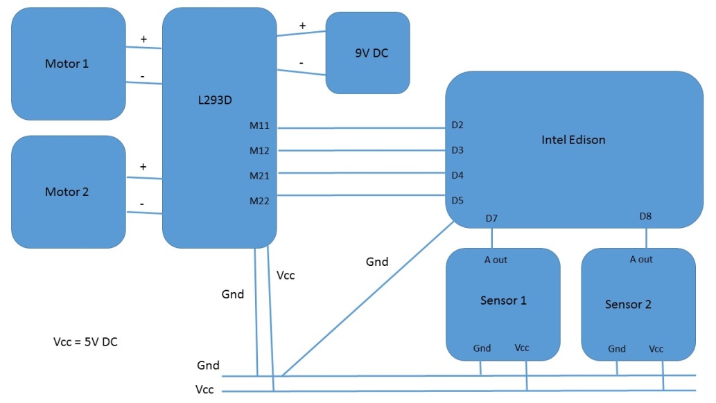
The preceding circuit is a combination of what we've done so far in this chapter. A common ground, a Vcc line, is created that connects the L293D, Intel Edison, and the sensors. The 9V DC power supply powers the motors, while the control pins are responsible for sending control signals from the Intel Edison. The output of the sensors is connected to the digital pins of the Intel Edison. Finally, the motor driver controls the motors based on the control signals.
If you have a close look at the preceding circuit diagram, then everything fits into the typical robotics architecture:

But the dashboard is missing. We may add a dashboard, but as of now, we aren't interested in that aspect.
Now that the hardware is done with all the connections and circuitry, let's add a code to it to make it run.
The algorithm is very simple, as follows:
- Check the left sensor value.
- If detected, turn left.
- Or else, check the right sensor value.
- If detected, turn right.
- Else if both detected.
- Stop the motion.
- Or else, move forward.
The following is the code for this:
#define M11 2
#define M12 3
#define M21 4
#define M22 5
#define S1 7
#define S2 8
inta,b;
void setup()
  {
    pinMode(M11,OUTPUT);
    pinMode(M12,OUTPUT);
    pinMode(M21,OUTPUT);
    pinMode(M22,OUTPUT);
    pinMode(S1,INPUT);
    pinMode(S2,INPUT);
  }
void loop()
  {
    a=digitalRead(S1);
    b=digitalRead(S2);
    //Left turn condition
    if(a==1&&b==0)
      {
        left();
      }
    //Right turn condition
    else if(a==0&&b==1)
      {
        right();
      }
    //Stop condition
    else if(a==1&&b==1)
      {
        stop();
      }
    //By default forward
    else
      {
        forward();
      }
  }
void forward()
  {
    digitalWrite(M11,HIGH);
    digitalWrite(M12,LOW);
    digitalWrite(M21,HIGH);
    digitalWrite(M22,LOW);
  }
void backward()
  {
    digitalWrite(M11,LOW);
    digitalWrite(M12,HIGH);
    digitalWrite(M21,LOW);
    digitalWrite(M22,HIGH);
  }
void right()
  {
    digitalWrite(M11,HIGH);
    digitalWrite(M12,LOW);
    digitalWrite(M21,LOW);
    digitalWrite(M22,HIGH);
  }
void left()
  {
    digitalWrite(M11,LOW);
    digitalWrite(M12,HIGH);
    digitalWrite(M21,HIGH);
    digitalWrite(M22,LOW);
  }
void stop()
  {
    digitalWrite(M11,LOW);
    digitalWrite(M12,LOW);
    digitalWrite(M21,LOW);
    digitalWrite(M22,LOW);
  }
In the preceding code, which is very similar to that of the motor testing, only the void loop() is replaced by the main logic, as described in the algorithm. We've used macros for defining sensor and motor pins.
The code initially sets the pins to either input mode or output mode. Next, we store the input values of the sensor. Finally, based on the sensor input, we process the robot motion.
After you burn the code on your Intel Edison, the robot should run. Try a simple track initially, and once your robot runs, then go for a more tight turns. Again, it should be kept in mind that in the preceding code, our right sensor may be your left sensor. In that case you must change the position or just change the condition.
Thus, through a combination of sensors and very simple processing, we can control the motors of a robot and follow a line. Now, if the problem statement asked you to reverse the condition and follow a white line on a black surface, we'd need to tamper with the code a bit, especially in condition checking. The result will be as follows:
void loop()
{
int a,b;
  a=digitalRead(S1);
  b=digitalRead(S2);
  //Left turn condition
if(a==0&&b==1)
  {
left();
  }
  //Right turn condition
else if(a==1&&b==0)
  {
right();
  }
  //Stop condition
else if(a==0&&b==0)
  {
stop();
  }
  //By default forward
else
  {
forward();
  }
}
Just the 1s and 0s need to be interchanged.
Now that we have fairly basic knowledge of developing a basic line follower robot, let's have a brief look at an advanced form of line following and tackle some of the basic concepts.