
For making systems wireless in robotics, there are many options available. The choice of hardware and protocol depends on certain factors, which are as follows:
- Availability of mobile network coverage
- Rules and regulations over RF in your operating country
- Maximum distance required
- Availability of Internet connectivity
If we use a GSM module, then mobile network coverage is a must. We may need to get clearance for the RF and ensure that it does not interfere with other signals. The maximum distance is another factor to consider, as distance is limited when using Bluetooth. Bluetooth connectivity can be hampered if the distance exceeds. The same goes for RF, but RF coverage can be increased based on the antenna used. If there is Internet connectivity over an area, then MQTT itself can be used, which was again discussed in Chapter 3, Intel Edison and IoT (Home Automation).
RF, or radio frequency, can be used for small applications. Wi-Fi can also be used with Edison, but let's cover a wide spectrum of devices and take a look into how RF can be used.
Normally, RF modules follow a Universal Asynchronous Receiver Transmitter (UART) protocol. These generally have a USB link and a serial link. A serial link can be converted with a USB link using a serial to USB converter. There are many options to choose from when buying an RF module set.
Normally, the pin out of a RF serial link is shown as follows:

Here is a product of http://robokits.co.in/, which we used in our projects:

The module can consist of five pins. We only need to deal with the four pins, as mentioned in the preceding figure.
An RF kit is used to manually control the robot wirelessly by sending commands. These are sent using serial port communication. The controller may use an RF module that has a USB link, or you can use a serial to USB converter to connect it to your PC. The connections of an RF serial link with a serial to USB converter is shown as follows:
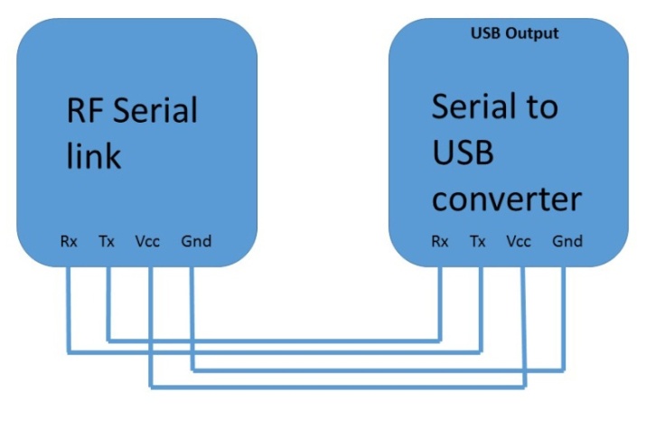
The connection shown earlier is for connecting an RF serial link to a USB. This applies to the computer side as we want to control it by a PC. We must use two RF modules; one is for Edison and the other is for the controller app or the PC. To connect the RF module to Intel Edison, have a look at the following image:
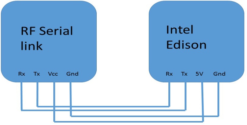
Intel Edison has Rx and Tx pins, which are pins 0 and 1 respectively. The overall architecture is shown as follows:

Now that we know how the hardware pieces are used for wireless communication, the programming part of the preceding model in Intel Edison is ridiculously simple. Just replace Serial with Serial1, as we are using the Rx and Tx pins:
void setup()
  {
    Serial1.begin(9600);
  }

void loop()
  {
    Serial1.println("Hi, Reporting in from Intel Edison");
    delay(500);
  }
The preceding code sends data to a controller app by using the Rx and Tx pins over an RF network. Now we will have a look on the controller application side, where we will develop a WPF application to control our device.