
The entire connection is shown in the following figure:
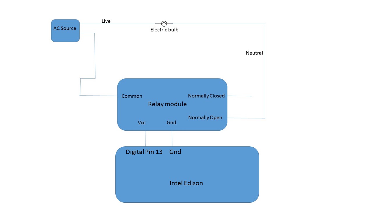
Circuit diagram for home automation project
The circuit adds Intel Edison because the relay circuit will be controlled by the controller. The relay here just acts as an interfacing unit to the AC load.
While the relay is being operated, please do not touch the underside of it or you may get an AC electric shock, which can be dangerous.
To test whether the circuit is working or not, try out a simple program using the Arduino IDE:
#define RELAY_PIN 13 void setup()
{
  pinMode(RELAY_PIN,OUTPUT); //Set relay pin to output
}
void loop
{
  digitalWrite(RELAY_PIN, HIGH); //Set relay to on position
}
The code should switch the position of the switch from the NC position to the NO position, thus completing the circuit, leading your bulb to glow. Don't forget to switch on the AC power supply.
Once you have the final circuit ready, we'll move forward with the development of the WPF application, which will control Edison.