chapter 7
Power Supplies
“I have the power!”
—HE-MAN

In this chapter, you will learn how to
■ Explain the basics of electricity
■ Describe the details of powering the PC
■ Install and maintain power supplies
■ Explain power supply troubleshooting and fire safety
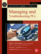
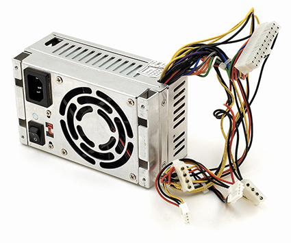
Computers need electricity to run. Where this electricity comes from depends on the device. Mobile devices use batteries (covered in detail in Chapter 23). Desktop computers need a special box—the power supply unit (PSU)—that takes electricity from the wall socket and transforms it into electricity your computer can use. Figure 7.1 shows a typical power supply.
• Figure 7.1 Power supply about to be mounted inside a system unit
As simple as this appears on the surface, power supply issues are of critical importance for techs. Problems with power create system instability, crashes, and data loss—all things most computer users would rather avoid! Good techs know an awful lot about powering the PC, from understanding the basic principles of electricity to knowing the many variations of PC power supplies. Plus, you need to know how to recognize power problems and implement the proper solutions. Too many techs fall into the “just plug it in” camp and never learn how to deal with power, much to their clients’ unhappiness.

Historical/Conceptual
■ Understanding Electricity
Electricity is a flow of negatively charged particles, called electrons, through matter. All matter enables the flow of electrons to some extent. This flow of electrons is very similar to the flow of water through pipes; so similar that the best way to learn about electricity is by comparing it to how water flows through pipes. Let’s talk about water for a moment.
Water comes from the ground, through wells, aquifers, rivers, and so forth. In a typical city, water comes to you through pipes from the water supply company that took it from the ground. What do you pay for when you pay your water bill each month? You pay for the water you use, certainly, but built into the price of the water you use is the surety that when you turn the spigot, water will flow at a (more or less) constant rate. The water sits in the pipes under pressure from the water company, waiting for you to turn the spigot.
Electricity works essentially the same way as water. Electric companies gather or generate electricity and then push it to your house under pressure through wires. Just like water, the electricity sits in the wires, waiting for you to plug something into the wall socket, at which time it’ll flow at a (again, more or less) constant rate. You plug a lamp into an electrical outlet and flip the switch, electricity flows, and you have light. You pay for the quantity of reliable, constant-voltage electricity your home or business uses.
The pressure of the electrons in the wire is called voltage and is measured in units called volts (V). See Figure 7.2.

• Figure 7.2 Electrical voltage as water pressure
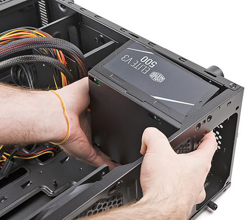
The number of electrons moving past a certain point on a wire is called the current (or amperage), which is measured in units called amperes (amps or A). See Figure 7.3.
• Figure 7.3 Electrical amperage as amount of water flowing
The amps and volts needed so that a particular device will function is expressed as how much wattage (watts or W) that device needs. The correlation between the three is remarkably simple math: V × A = W. Let’s see how this formula helps PC techs.
Wires of all sorts—whether copper, tin, gold, or platinum—have a slight resistance to the flow of electrons, just as water pipes have a slight amount of friction that resists the flow of water. Resistance to the flow of electrons is measured in ohms (Ω).
■ Pressure = voltage (V)
■ Volume flowing = amperes (A)
■ Power = wattage (W)
■ Resistance = ohms (Ω)

A particular thickness of wire only holds so much current at a time. If you push too much through, the wire will overheat and break, much as an overloaded water pipe will burst. To make sure you use the right wire for the right job, all electrical wires have an amperage rating, such as 20 amps. If you try to push 30 amps through a 20-amp wire, the wire will break, and electrons will seek a way to return into the ground. Not a good thing, especially if the path back to ground is through you!
Circuit breakers and ground wires provide the basic protection from accidental overflow. A circuit breaker is a heat-sensitive or electromagnetically operated electrical switch rated for a specified amperage. If you push too much amperage through the circuit breaker, the wiring inside detects the increase in heat or current and automatically opens, stopping the flow of electricity before the wiring overheats and breaks. You reset the circuit breaker to reestablish the circuit, and electricity flows once more through the wires. A ground wire provides a path of least resistance for electrons to flow back to ground in case of an accidental overflow.
Many years ago, home and building electrical supplies used fuses instead of circuit breakers. Fuses are small devices with a tiny filament designed to break if subjected to too much current. Unfortunately, fuses had to be replaced every time they blew, making circuit breakers much more convenient. Even though you no longer see fuses in a building’s electrical circuits, many electrical devices—such as a PC’s power supply—often still use fuses for their own internal protection. Once blown, these fuses are not replaceable by users or technicians without special training and tools.
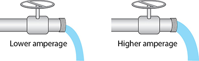
Electricity comes in two flavors: direct current (DC), in which the electrons flow in one direction around a continuous circuit, and alternating current (AC), in which the flow of electrons alternates direction back and forth in a circuit (see Figure 7.4). Most electronic devices use DC power, but all power companies supply AC power because AC travels long distances much more efficiently than DC.
• Figure 7.4 Diagrams showing DC and AC flow
1101
■ Powering the PC
Your PC uses DC voltage, so some conversion process must take place before the PC can use AC power from the power company. The power supply in a computer converts high-voltage AC power from the wall socket to low-voltage DC. The first step in powering the PC, therefore, is to get and maintain a good supply of AC power. Second, you need a power supply to convert AC to the proper voltage and amperage of DC power for the motherboard and peripherals. Finally, you need to control the by-product of electricity use—namely, heat. Let’s look at the specifics of powering the PC.
Supplying AC
Every PC power supply must have standard AC power from the power company. The power supply gets that power with a power cord that plugs into an electrical outlet on one end and to the power supply via a standard IEC-320 connector on the other. In the United States, standard AC comes in somewhere between input 110 and 120 V, often written as ~115 VAC (volts of alternating current). Most of the rest of the world uses 230 VAC, so modern power supplies are designed to support both voltages, aka dual voltage. Not only are they dual voltage, but they’re also autosensing. Just plug in the power supply and it automatically adjusts to whatever voltage is offered.
Older power supplies were also dual voltage but not autosensing. These power supplies came with a voltage-selection switch and are referred to as fixed-input. Figure 7.5 shows the back of a power supply. Note the three components, from top to bottom: the hard on/off switch, the 115/230 switch, and the IEC-320 connector.

• Figure 7.5 Back of fixed-input power supply, showing typical switches and power connection
![]()
Testing Your Power Source
Before you plug any critical components into an AC outlet, take a moment to test the outlet first by using a multimeter or a device designed exclusively to test outlets. Failure to test AC outlets properly can result in inoperable or destroyed equipment, as well as possible electrocution. The IEC-320 plug has three holes, called hot, neutral, and ground. These names describe the function of the wires that connect to them behind the wall plate. The hot wire carries electrical voltage, much like a pipe that delivers water. The neutral wire carries no voltage, but instead acts like a water drain, completing the circuit by returning electricity to the local source, normally a breaker panel. The ground wire makes it possible for excess electricity to return safely to the ground, such as in a short-circuit condition.
When testing AC power, you want to check for three things: that the hot outputs approximately 115 V (or whatever the proper voltage is for your part of the world), that the neutral connects to ground (0 V output), and that the ground connects to ground (again, 0 V). Figure 7.6 shows the voltages at an outlet. You can use a multimeter—often also referred to as a volt-ohm meter (VOM) or digital multimeter (DMM)—to measure several aspects of electrical current. A multimeter consists of two probes, an analog or digital meter, and a dial to set the type of test you want to perform. Refer to Figure 7.7 to become familiar with the components of the multimeter.

• Figure 7.6 Outlet voltages
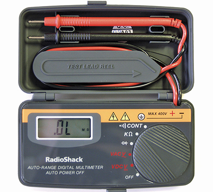
• Figure 7.7 Author’s ancient but reliable Radio Shack digital multimeter
Note that some multimeters use symbols rather than letters to describe AC and DC settings. For example, the V with the solid line above a dashed line in Figure 7.8 refers to direct current. The V~ stands for alternating current.
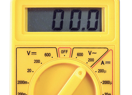
• Figure 7.8 Multimeter featuring DC and AC symbols
AC Adapters
Many computing devices use an AC adapter rather than an internal power supply. AC adapters tend to look the same, a black box with two cables. One cable goes to a wall power outlet, and the other cable plugs into your device (see Figure 7.9).
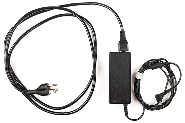
• Figure 7.9 Typical AC adapter
Even though it sits outside a device, an AC adapter converts AC current to DC, just like a power supply. Unlike internal power supplies, AC adapters are rarely interchangeable. Although manufacturers of different devices often use the same kind of plug on the end of the AC adapter cable, these adapters are not necessarily interchangeable. In other words, just because you can plug an AC adapter from your friend’s laptop into your laptop does not mean it’s going to work.
You need to make sure that three things match before you plug an AC adapter into a device: voltage, amperage, and polarity. If either the voltage or amperage output is too low, the device won’t run. If the polarity is reversed, it won’t work, just like putting a battery in a flashlight backward. If either the voltage or amperage—especially the former—is too high, on the other hand, you can very quickly toast your device. Don’t do it! Always check the voltage, amperage, and polarity of a replacement AC adapter before you plug it into a device.
Most multimeters offer at least four types of electrical tests: continuity, resistance, AC voltage (VAC), and DC voltage (VDC). Continuity tests determine whether electrons can flow from one end of a wire to the other end. If so, you have continuity; if not, you don’t. You can use this setting to determine if a fuse is good or to check for breaks in wires. If your multimeter doesn’t have a continuity tester (many cheaper multimeters do not), you can use the resistance tester. A broken wire or fuse will show infinite resistance, while a good wire or fuse will show no resistance. Testing AC and DC voltages is a matter of making sure the measured voltage is what it should be.
 Try This!
Using a Multimeter to Test AC Outlets
Every competent technician knows how to use a multimeter, so if you haven’t used one in the past, get hold of one and work through this scenario. Your boss tasks you with checking the existing electrical outlets in a new satellite location for the company. Caution: During this exercise, do not physically touch any of the metal parts of the probes or sockets!
First you need to set up the meter for measuring AC. Follow these steps:
1. Move the selector switch to the AC V (usually red). If multiple settings are available, put it into the first scale higher than 120 V (usually 200 V). Auto-range meters set their own range; they don’t need any selection except AC V.
2. Place the black lead in the common (–) hole. If the black lead is permanently attached, ignore this step.
3. Place the red lead in the V-Ohm-A (+) hole. If the red lead is permanently attached, ignore this step.
Once you have the meter set up for AC, go through the process of testing the various wires on an AC socket. Just don’t put your fingers on the metal parts of the leads when you stick them into the socket! Follow these steps:
1. Put either lead in hot, the other in neutral. You should read 110 to 120 VAC.
2. Put either lead in hot, the other in ground. You should read 110 to 120 VAC.
3. Put either lead in neutral, the other in ground. You should read 0 VAC.
If any of these readings is different from what is described here, it’s time to call an electrician.
Using Special Equipment to Test AC Voltage
A number of good AC-only testing devices are available. With these devices, you can test all voltages for an AC outlet by simply inserting them into the outlet. Be sure to test all of the outlets the computer system uses: power supply, external devices, and monitor. Although convenient, these devices aren’t as accurate as a multimeter. My favorite tester is a seemingly simple tool available from a number of manufacturers. This handy circuit tester (see Figure 7.10) provides three light-emitting diodes (LEDs) that describe everything that can go wrong with a plug.

• Figure 7.10 Circuit tester
1102
Equipment Grounding
Computer equipment safety starts with proper grounding. The ground wire functions as an emergency outlet for excess current in case of any short or malfunction of a device. Don’t assume that a convenient three-prong outlet has proper grounding, especially in older buildings. Use a multimeter to check that ground wire.
Protecting the PC from Spikes and Sags in AC Power
If all power companies could supply electricity in smooth, continuous flows with no dips or spikes in pressure, the next two sections of this chapter would be irrelevant. Unfortunately, no matter how clean the AC supply appears to a multimeter, the truth is that voltage from the power company tends to drop well below (sag) and shoot far above (power surge or spike) the standard 115 V (in the United States). These sags and spikes usually don’t affect lamps and refrigerators in such scenarios, but they can keep your PC from running or can even destroy a PC or peripheral device. Two essential devices handle spikes and sags in the supply of AC: surge suppressors and uninterruptible power supplies.
Surge Suppressors Surges or spikes are far more dangerous than sags. Even a strong sag only shuts off or reboots your PC; any surge can harm your computer, and a strong surge destroys components. Given the seriousness of surges, every PC should use a surge suppressor device that absorbs the extra voltage from a surge to protect the PC. The power supply does a good job of surge suppression and handles smaller surges without a problem. But the power supply takes a lot of damage from larger surges and will eventually fail. To protect your power supply, a dedicated surge suppressor works between the power supply and the outlet to protect the system from power surges (see Figure 7.11).

• Figure 7.11 Surge suppressor
Most people tend to spend a lot of money on their PC and for some reason suddenly get cheap on the surge suppressor. Don’t do that! Make sure your surge suppressor has the UL LCC 1449 for 330-V rating to ensure substantial protection for your system. UL (https://www.ul.com) is a U.S.-based, not-for-profit, widely recognized industry testing laboratory whose testing standards are very important to the consumer electronics industry. Additionally, check the joules rating before buying a new surge suppressor. A joule is a unit of electrical energy. How much energy a surge suppressor can handle before it fails is described in joules. Most authorities agree that your surge suppressor should rate at a minimum of 2000 joules—and the more joules, the better the protection. My surge suppressor rates at 3500 joules.
While you’re protecting your system, don’t forget that surges also come from telephone and cable connections. If you use anything with copper cables—cable modems, or even an old DSL modem—make sure to get a surge suppressor that includes support for these types of connections. Many manufacturers make surge suppressors with telephone line protection (see Figure 7.12).

• Figure 7.12 Surge suppressor with cable and telephone line protection
No surge suppressor works forever. Make sure your surge suppressor has a test/reset button so you’ll know when the device has—as we say in the business—turned into an extension cord. If your system takes a hit and you have a surge suppressor, call the company! Many companies provide cash guarantees against system failure due to surges, but only if you follow their guidelines.
![]()
If you want really great surge suppression, you need to move up to power conditioning. Your power lines take in all kinds of strange signals that have no business being in there, such as electromagnetic interference (EMI) and radio frequency interference (RFI). Most of the time, this line noise is so minimal it’s not worth addressing, but occasionally events (such as lightning) generate enough line noise to cause weird things to happen to your PC (keyboard lockups, messed-up data). All better surge suppressors add power conditioning to filter out EMI and RFI.
 Tech Tip
Clamping Voltage
Surge suppression isn’t just about joules. Surge suppressors are also rated in clamping voltage, in which an overvoltage condition is “clamped” to a more manageable voltage for a certain amount of time. Good consumer suppressors can clamp 600 volts down to 180 volts or less for at least 50 microseconds and can do so on either the hot line or neutral line.
Uninterruptable Power Supply An uninterruptable power supply (UPS) protects your computer (and, more importantly, your data) in the event of a power sag or power outage. Figure 7.13 shows a typical UPS. It essentially contains a big battery that provides AC power to your computer regardless of the power coming from the AC outlet. An example of a UPS is the battery backup that we use in our personal computers, laptops, and tablets. These devices have integrated battery technology that charges the device with DC power.
• Figure 7.13 UPS
All UPSs are measured in both watts (the true amount of power they supply in the event of a power outage) and in volt-amps (VA). Volt-amps is the amount of power the UPS could provide if the devices took power from the UPS in a perfect way. Your UPS provides perfect AC power, moving current smoothly back and forth 60 times a second (or 50 in other parts of the world). Power supplies, monitors, and other devices, however, may not take all of the power the UPS has to offer at every point as the AC power moves back and forth, resulting in inefficiencies. If your devices took all of the power the UPS offered at every point as the power moved back and forth, VA would equal watts.
If the UPS makers knew ahead of time exactly what devices you planned to plug into their UPS, they could tell you the exact watts, but different devices have different efficiencies, forcing the UPS makers to go by what they can offer (VAs), not what your devices will take (watts). The watts value they give is a guess, and it’s never as high as the VAs. The VA rating is always higher than the wattage rating.
Because you have no way to calculate the exact efficiency of every device you’ll plug into the UPS, go with the wattage rating. You add up the total wattage of every component in your PC and buy a UPS with a higher wattage. You’ll spend a lot of time and mental energy figuring precisely how much wattage your computer, monitor, drives, and so on require to get the proper UPS for your system. But you’re still not finished! Remember that the UPS is a battery with a limited amount of power, so you then need to figure out how long you want the UPS to run when you lose power.
Tech Tip
UPS Technologies
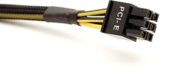
There are two main types of UPS: online, where devices are constantly powered through the UPS’s battery, and standby, where devices connected to the UPS receive battery power only when the AC sags below ~80–90 V. Another type of UPS is called line-interactive, which is similar to a standby UPS but has special circuitry to handle moderate AC sags and surges without the need to switch to battery power.
The quicker and far better method to use for determining the UPS you need is to go to any of the major surge suppressor/UPS makers’ Web sites and use their handy power calculators. My personal favorite is on the APC by Schneider Electric Web site: https://www.apc.com (type UPS selector in the search field). APC makes great surge suppressors and UPSs, and the company’s online calculator will show you the true wattage you need—and teach you about whatever new thing is happening in power at the same time.
Try This!
Shopping for a UPS
When it comes to getting a UPS for yourself or a client, nothing quite cuts through the hype and marketing terms like a trip to the local computer store to see for yourself. You need excuses to go to the computer store, so here’s a valid one for you.
1. Go to your local computer store—or visit an online computer site if no stores are nearby—and find out what’s available.
2. Answer this question: How can you tell the difference between an online UPS and a standby UPS?
Every UPS also has surge suppression and power conditioning, so look for the joule and UL 1449 ratings. Also look for replacement battery costs—some UPS replacement batteries are very expensive. Last, look for a UPS with a USB or Ethernet (RJ-45) connection. These handy UPSs come with monitoring and maintenance software (see Figure 7.14) that tells you the status of your system and the amount of battery power available, logs power events, and provides other handy options.

• Figure 7.14 UPS management application
Table 7.1 gives you a quick look at the low end and the higher end of UPS products.
Table 7.1 Typical UPS Devices
1101
Supplying DC
After you’ve ensured the supply of good AC electricity for the PC, the power supply unit takes over, converting public utility voltage AC (115/120 V in the United States, 230 V in many other countries) into several DC voltages (notably, 3.3 V, 5 V, and 12 V) usable by the delicate interior components. Power supplies come in a large number of shapes and sizes, but the most common size by far is the standard 150 mm × 140 mm × 86 mm desktop PSU shown in Figure 7.15.

• Figure 7.15 Desktop PSU
The PC uses the 12-V current to power motors on devices such as hard drives and optical drives, and it uses the 3.3- and 5-V current for support of onboard electronics. Manufacturers may use these voltages any way they wish, however, and may deviate from these assumptions. Power supplies also come with standard connectors for the motherboard and interior devices.
Power to the Motherboard
Modern motherboards use a 20- or 24-pin P1 power connector. Some motherboards may require special 4-, 6-, or 8-pin connectors to supply extra power (see Figure 7.16). We’ll talk about each of these connectors in the form factor standards discussion later in this chapter.

• Figure 7.16 Motherboard power connectors
Power to Peripherals: Molex, Mini, and SATA
Many devices inside the PC require power. These include hard drives, solid-state drives, optical drives, and fans. The typical PC power supply has at least three types of connectors that plug into peripherals: Molex, mini, and SATA. (Higher-end video cards get their own connector(s) as well, covered a little later in this chapter.)
Molex Connectors Now over 50 years old, the Molex connector supplies 5-V and 12-V current for fans and older drives (see Figure 7.17). The Molex connector has notches, called chamfers, that guide its installation. The tricky part is that Molex connectors require a firm push to plug in properly, and a strong person can defeat the chamfers, plugging a Molex in upside down. Not a good thing. Always check for proper orientation before you push it in!

• Figure 7.17 Molex connector
Mini Connectors A few power supplies still support the mini connector or Berg connector (see Figure 7.18). The mini supplies 5 V and 12 V to peripherals. Originally adopted as the standard connector on 3.5-inch floppy disk drives, you’ll still see the occasional device needing this connector.

• Figure 7.18 Mini connector
Try This!
Testing DC
A common practice for techs troubleshooting a system is to test the DC voltages coming out of the power supply. Even with good AC, a bad power supply can fail to transform AC to DC at voltages needed by the motherboard and peripherals. The best way to learn how to perform this common technique is to try it yourself, so grab your trusty multimeter and walk through the following steps on a powered-up PC with the side cover removed. Note that you must have P1 connected to the motherboard and the system must be running (you don’t have to be in Windows or Linux, of course).
1. Switch your multimeter to DC, somewhere around 20 V DC if you need to make that choice. Make sure your leads are plugged into the multimeter properly: red to hot, black to ground. The key to testing DC is that which lead you touch to which wire matters. Red goes to hot wires of all colors; black always goes to ground. If your wires are all the same color, look up a pin-out diagram for the connector. For a Molex connector, pin 1 will be 12 V and pin 4 will be 5 V; a quick way to tell is with the chamfers up, pin 1 is on the left.
2. Plug the red lead into the red wire socket (pin 4) of a free Molex connector and plug the black lead into one of the two black wire sockets (pins 2 or 3). You should get a reading of ~5 V. What do you have?
3. Now move the red lead to the yellow socket (pin 1). What voltage do you get?
4. Testing the P1 connector is a little more complicated. You push the red and black leads into the top of P1, sliding in alongside the wires until you bottom out. Leave the black lead in one of the black wire ground sockets. Move the red lead through all of the colored wire sockets. What voltages do you find?
![]()
SATA Power Connectors Serial ATA (SATA) drives need a 15-pin SATA power connector (see Figure 7.19). The larger pin count supports the SATA hot-swappable feature and 3.3-, 5-, and 12-V devices. The 3.3-V pins are not used in any current iteration of SATA drives and are reserved for possible future use. All three generations of SATA use the same power connectors. SATA power connectors are L shaped, making it almost impossible to insert one incorrectly into a SATA drive. No other device on a computer uses the SATA power connector. For more information about SATA drives, see Chapter 8.

• Figure 7.19 SATA power connector
Splitters and Adapters You may occasionally find yourself without enough connectors to power all of the devices inside your PC. In this case, you can purchase splitters to create more connections (see Figure 7.20). You might also run into the phenomenon of needing a SATA connector but having only a spare Molex. Because the voltages on the wires are the same, a simple adapter will take care of the problem nicely.

• Figure 7.20 Molex splitter
ATX
The original ATX power supplies had two distinguishing physical features: the motherboard power connector and soft power. Motherboard power came from a single cable with a 20-pin P1 motherboard power connector. ATX power supplies also had at least two other cables, each populated with two or more Molex or mini connectors for peripheral power.
When plugged in, ATX systems have 5 V running to the motherboard. They’re always “on,” even when powered down. The power switch you press to power up the PC isn’t a true power switch like the light switch on the wall in your bedroom. The power switch on an ATX system simply tells the computer whether it has been pressed. The BIOS or operating system takes over from there and handles the chore of turning the PC on or off. This is called soft power.
Using soft power instead of a physical switch has several important benefits. Soft power prevents a user from turning off a system before the operating system has been shut down. It enables the PC to use power-saving modes that put the system to sleep and then wake it up when you press a key, move a mouse, or receive an e-mail (or other network traffic). (See Chapter 23 for more details on sleep mode.)
All of the most important settings for ATX soft power reside in CMOS setup. Boot into CMOS and look for a Power Management section. Take a look at the Power Button Function option in Figure 7.21. This determines the function of the on/off switch. You may set this switch to turn off the computer, or you may set it to the more common 4-second delay.

• Figure 7.21 Soft power setting in CMOS
ATX did a great job supplying power for more than a decade, but over time more powerful CPUs, multiple CPUs, video cards, and other components began to need more current than the original ATX provided. This motivated the industry to introduce several updates to the ATX power standards: ATX12V 1.3, EPS12V, multiple rails, ATX12V 2.0, other form factors, and active PFC.
ATX12V 1.3 The first widespread update to the ATX standard, ATX12V 1.3, came out in 2003. This introduced a 4-pin motherboard power connector, unofficially but commonly called the P4 power connector, that provides more 12-V power to assist the 20/24-pin P1 motherboard power connector. Any power supply that provides a P4 connector is called an ATX12V power supply. The term “ATX” was dropped from the ATX power standard, so if you want to get really nerdy you can say—accurately—that there’s no such thing as an ATX power supply. All power supplies—assuming they have a P4 connector—are ATX12V or one of the later standards.
The ATX12V 1.3 standard also introduced a 6-pin auxiliary connector—commonly called an AUX connector—to supply increased 3.3- and 5-V current to the motherboard (see Figure 7.22). This connector was based on the motherboard power connector from the precursor of ATX, called AT.
• Figure 7.22 Auxiliary power connector
 Cross Check
ATX Form Factor
The power supply form factor alone does not define a system as ATX or one of the later varieties; you have to discuss the motherboard as well. Flip back to Chapter 6 and see if you can put the full picture of the ATX standard together. What defines a system as ATX? What ATX form factors can you purchase?
The introduction of these two extra power connectors caused the industry some teething problems. In particular, motherboards using AMD CPUs tended to need the AUX connector, while motherboards using Intel CPUs needed only the P4. As a result, many power supplies came with only a P4 or only an AUX connector to save money. The biggest problem with the ATX12V standard was the lack of enforcement—it made a lot of recommendations but few requirements, giving PSU makers too much choice (such as choosing or not choosing to add AUX and P4 connectors) that weren’t fixed until later versions.
EPS12V Server motherboards are thirsty for power, and sometimes ATX12V 1.3 just didn’t cut it. An industry group called the Server System Infrastructure (SSI) developed a non-ATX standard motherboard and power supply called EPS12V. An EPS12V power supply came with a 24-pin main motherboard power connector that resembled a 20-pin ATX connector, but it offered more current and thus more stability for motherboards. It also came with an AUX connector, an ATX12V P4 connector, and a unique 8-pin connector. That’s a lot of connectors! EPS12V power supplies were not interchangeable with ATX12V power supplies.
EPS12V may not have seen much life beyond servers, but it introduced a number of power features, some of which eventually became part of the ATX12V standard. The most important issue was something called rails.
Rails Generally, the PC’s power comes from a single transformer that takes the AC current from a wall socket and converts it into DC current that is split into three primary DC voltage rails: 12 V, 5 V, and 3.3 V. Groups of wires run from each of these voltage rails to the various connectors.
Each rail has a maximum amount of power it can supply. Normal computer use rarely approaches this ceiling, but powerful computers with advanced processors and graphics cards require more power than some rails can provide. In the past, 12-V rails only supplied about 18 amps, which wasn’t enough to power all that high-end equipment.
The most popular solution was to include multiple 12-V rails in the power supply. This worked fine, but you needed to make sure that you weren’t drawing all the power from the same 12-V rail. The key circuitry that monitors the amount of amperage going through each rail, called the over-current protection (OCP), will shut down the power supply if the current goes beyond its cap. In a single-rail system, a single OCP circuit monitors all the pathways. In a multi-rail system, each pathway gets its own OCP circuit.
When first implemented, multi-rail power supplies didn’t do a great job balancing the circuitry, so enthusiasts still ran into problems with systems shutting down under heavy load. This has been fixed since 2008 or so, so any multi-rail PSU you buy today can handle whatever you throw at it.
Today’s power supply manufacturers produce single- and multi-rail high-amperage PSUs. You can find power supplies now with 12-V rails pushing 70 amps or more!
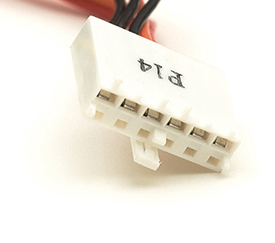
ATX12V 2.0 The ATX12V 2.0 standard incorporated many of the good ideas of EPS12V, starting with the 24-pin connector. This 24-pin motherboard power connector is backward compatible with the older 20-pin connector, so users don’t have to buy a new motherboard if they use an ATX12V 2.0 power supply. ATX12V 2.0 requires two 12-V rails for any power supply rated higher than 230 W. ATX12V 2.0 dropped the AUX connector and requires SATA hard drive connectors.
Many ATX12V 2.0 power supplies have a convertible 20-to-24-pin motherboard adapter. These are handy if you want to make a nice “clean” connection, because many 20-pin connectors have interfaces that prevent plugging in a 24-pin connector. You’ll also see many 24-pin connectors constructed in such a way that you can slide off the extra four pins. Figure 7.23 shows 20-pin and 24-pin connectors; Figure 7.24 shows a convertible adapter. Although they look similar, those extra four pins won’t replace the P4 connector. They are incompatible!
• Figure 7.23 20- and 24-pin connectors

• Figure 7.24 Convertible motherboard power connector
Many modern ATX motherboards feature an 8-pin CPU power connector like the one found in the EPS12V standard to help support high-end CPUs that demand a lot of power. This connector is referred to by several names, including EPS12V, EATX12V, and ATX12V 2x4. One half of this connector will be pin compatible with the P4 power connector, and the other half may be under a protective cap. Be sure to check the motherboard installation manuals for recommendations on when to use the full 8 pins. For backward compatibility, some power supplies provide an 8-pin power connector that can split into two 4-pin sets, one of which is the P4 connector.
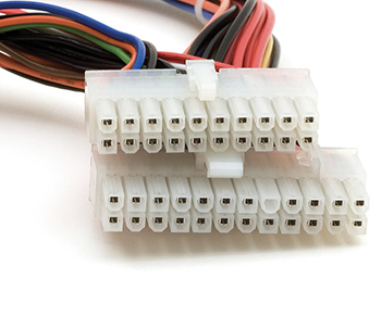
Another notable connector is the auxiliary PCI Express (PCIe) power connector. Figure 7.25 shows the 6-pin PCIe power connector. Some motherboards add a Molex socket for PCIe, and some cards come with a Molex socket as well. Higher-end video cards have one or two sockets that require specific PCIe 6/8-pin power connectors. The 8-pin PCIe connector should not be confused with the EPS12V connector, as they are not compatible. Some PCIe devices with the 8-pin connector will accept a 6-pin PCIe power connection instead, but this may put limits on their performance. Often, you’ll find that 8-pin PCIe power cables have two pins at the end that you can detach for easy compatibility with 6-pin devices.
• Figure 7.25 PCI Express 6-pin power connector
![]()
Niche-Market Power Supply Form Factors The demand for smaller and quieter PCs led to the development of niche-market power supply form factors. All use standard ATX connectors but differ in size and shape from standard ATX power supplies.
Here are some of the more common specialty power supply types:
■ Mini-ITX and microATX Smaller power supply form factors designed specifically for mini-ITX and microATX cases, respectively
■ TFX12V A small power supply form factor optimized for low-profile ATX systems
■ SFX12V A small power supply form factor optimized for systems using FlexATX motherboards (see Figure 7.26)
• Figure 7.26 SFX power supply
Active PFC Visualize the AC current coming from the power company as water in a pipe, smoothly moving back and forth, 50 or 60 times each second. A PC’s power supply, simply due to the process of changing this AC current into DC current, is like a person sucking on a straw on the end of this pipe. It takes gulps only when the current is fully pushing or pulling at the top and bottom of each cycle and creating an electrical phenomena—similar to the back pressure sometimes seen in water pipes—that’s called harmonics in the power industry. These harmonics create the humming sound you hear from electrical components. Over time, harmonics damage electrical equipment, causing serious problems with the power supply and other electrical devices on the circuit. Once you put a few thousand PCs with power supplies in the same local area, harmonics can even damage the electrical power supplier’s equipment!
Good PC power supplies come with active power factor correction (active PFC), extra circuitry that smooths out power coming from the wall before passing it to the main power supply circuits. This smoothing process eliminates any harmonics (see Figure 7.27). Never buy a power supply that does not have active PFC—all power supplies with active PFC will announce it on the box.

• Figure 7.27 Power supply advertising active PFC
Wattage Requirements
Every device in a PC requires a certain wattage to function. A typical hard drive draws about 15 W of power when accessed, for example, whereas an AMD Ryzen 9 5900X draws a whopping 105 W at peak usage. The total wattage of all devices combined is the minimum you need the power supply to provide.
When selecting a power supply for a system, in other words, make sure the power supply provides enough wattage to run the number of devices in the system. Also, the power supply needs to be able to support all the types of devices to be powered in the system. This is where knowing the wattage rating of your system is important. The wattage rating represents the amount of energy that’s converted from the power outlet to your computer’s internal power components. For example, a computer with a 75 percent power supply would consume approximately 400W if it generated 300W of power internally. I updated the video card in a system the other day, for example, from a card that required a single 6-wire power cable to one that required two 8-wire power cables (see Figure 7.28). The power supply clearly had to have the latter capability.
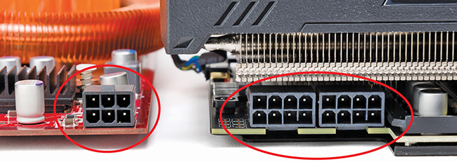
• Figure 7.28 Big jump in power requirements!
If the power supply cannot produce the wattage a system needs, that PC won’t work properly or at all. Because most devices in the PC require maximum wattage when first starting, the most common result of insufficient wattage is a paperweight that looks like a PC. This can lead to some embarrassing moments. You might plug in a new hard drive for a client, push the power button on the case, and nothing happens—a dead PC! Eek! You can quickly determine if insufficient wattage is the problem. Unplug the drive and power up the system. If the system boots up, the power supply is a likely suspect. The only fix for this problem is to replace the power supply with one that provides more wattage (or leave the new drive out—a less-than-ideal solution).
Tech Tip
Underpowered System Symptoms
An undersized power supply may not necessarily result in a complete paperweight. Some graphics cards that are dependent on additional rail power from a PSU may continue to operate but will do so at reduced frame rates. That means your games won’t play well, but the computer will function in other capacities. See Chapter 17 for the scoop on power-hungry video cards.
No power supply can convert 100 percent of the AC power coming from the power company into DC current, so all power supplies provide less power to the system than the wattage that they draw from the wall. The difference is lost in heat generation. The amount of this differential is advertised on the box. ATX12V 2.0 standards require a power supply to be at least 70 percent efficient, but many power supplies operate with better than 80 percent efficiency. Figure 7.29 shows a power supply clearly displaying its rating.

• Figure 7.29 PSU efficiency rating
Power supplies are typically graded for their efficiency under a voluntary standards program called 80 Plus. Under 80 Plus, power supplies are rated from 80 percent to 94 percent efficiency for a given load and badged with “metal labels” such as Bronze (80 percent), Gold (90 percent), or Titanium (94 percent) levels. These levels are achieved within a narrow range of watts provided, while lower levels of efficiency are achieved at higher and lower power draw. Power and efficiency curves are usually provided in the power supply documentation. More efficiency can tell you how many watts the system draws to supply sufficient power to the PC in actual use. The added efficiency means the power supply wastes less power, saving you money.
One common argument these days is that people buy power supplies that provide far more wattage than a system needs and therefore waste power. This is untrue. A power supply provides only the amount of power your system needs. If you put a 1500-W power supply into a system that needs only 250 W, that big power supply will put out only 250 W to the system. So buying an efficient, higher-wattage power supply gives you two benefits. First, running a power supply at less than 100 percent load helps it live longer. Second, you’ll have plenty of extra power when adding new components.
Try This!
Calculating Power Needs
The Internet has some great tools to help you determine power needs for specific computer systems. As noted earlier in the chapter, I recently upgraded from a decent video card to a high-end gaming card (and added another solid-state drive for more storage), after which I used an online tool to determine whether I needed to upgrade the power supply for a stable system. You will find yourself in similar situations as a tech, so try this!
Open a Web browser and check out the OuterVision Power Supply Calculator at https://outervision.com/power-supply-calculator. Enter the details on your desired systems and let this amazing tool do the math for you. Note the calculator compares efficiency information and even makes a recommended purchase for you (and not from OuterVision). It’s a very slick, very convenient tool. Bookmark it!
Don’t cut the specifications too tightly for power supplies. All power supplies produce less wattage over time, simply because of wear and tear on the internal components. If you build a system that runs with only a few watts of extra power available from the power supply initially, that system will most likely start causing problems within a year or less. Do yourself or your clients a favor and get a power supply that has more wattage than you need.
As a general recommendation for a new system, use at least a 550-W power supply. This is a common wattage and gives you plenty of extra power for booting as well as for whatever other components you might add to the system in the future.
■ Installing and Maintaining Power Supplies
Although installing and maintaining power supplies takes a little less math than selecting the proper power supply for a system, they remain essential skills for any tech. Installing takes but a moment and maintaining is almost as simple. Let’s take a look.
Installing
The typical power supply connects to the PC with four standard computer screws, mounted in the back of the case (see Figure 7.30). Unscrew the four screws and the power supply lifts out easily (see Figure 7.31). Insert a new power supply that fits the case and attach it by using the same four screws.
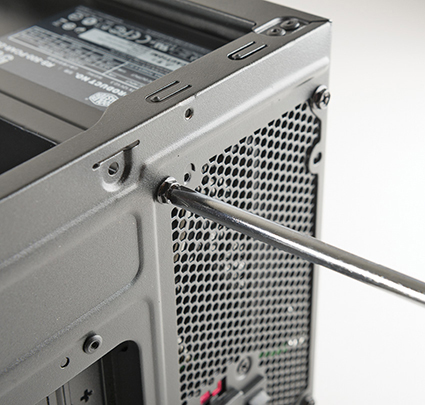
• Figure 7.30 Mounting screws for power supply

• Figure 7.31 Removing power supply from system unit
Handling ATX power supplies requires special consideration. Understand that an ATX power supply never turns off. As long as that power supply stays connected to a power outlet, the power supply will continue to supply 5 V to the motherboard. Always unplug an ATX system before you do any work! For years, techs bickered about the merits of leaving a PC plugged in or unplugged when servicing it. ATX settled this issue forever. Roughly half of all ATX power supplies provide a real on/off switch on the back of the PSU (see Figure 7.32). If you really need the system to be shut down with no power to the motherboard, use this switch.

• Figure 7.32 On/off switch for an ATX system
When working on an ATX system, you may find that using the power button is inconvenient. Perhaps you’re not using a case, or you haven’t bothered to plug the power button’s leads into the motherboard. That means there is no power button. One trick when in that situation is to use a metal key or a screwdriver to contact the two wires to start and stop the system (see Figure 7.33).
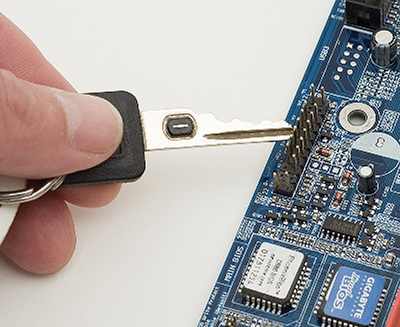
• Figure 7.33 Shorting the soft on/off jumpers
Your first task after acquiring a new power supply is simply to make sure that it works. Insert the motherboard power connectors before starting the system. If you have video cards with power connectors, plug them in too. You can wait to plug in other connectors such as hard drives until you have one successful boot—or if you’re feeling lucky, just plug everything in!
Cooling
Heat and computers are not the best of friends. Cooling is therefore a vital consideration when building a computer. Electricity equals heat. Computers, being electrical devices, generate heat as they operate, and too much heat can seriously damage a computer’s internal components.
The power supply fan provides the basic cooling for the PC (see Figure 7.34). It not only cools the voltage regulator circuits within the power supply but also provides a constant flow of outside air throughout the interior of the computer case. A dead power supply fan can rapidly cause tremendous problems, even equipment failure. If you ever turn on a computer and it boots just fine but you notice that it seems unusually quiet, check to see if the power supply fan has died. If it has, quickly turn off the PC and replace the power supply.
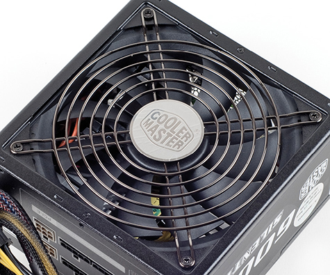
• Figure 7.34 Power supply fan
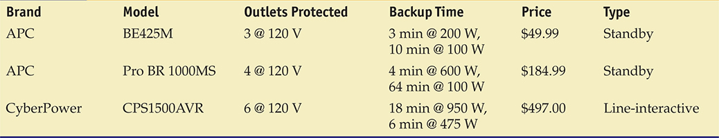
Some power supplies come with a built-in sensor to help regulate the airflow. If the system gets too hot, the power supply fan spins faster (see Figure 7.35).

• Figure 7.35 Three-wire fan sensor connector
Case fans are large, square fans that snap into special brackets on the case or screw directly to the case, providing extra cooling for key components (see Figure 7.36). Most cases come with a case fan, and no modern computer should really be without one or two.

• Figure 7.36 Case fan
The single biggest issue related to case fans is where to plug them in. Case fans may come with standard Molex connectors, which are easy to plug in, or they may come with three-pronged power connectors that connect to the motherboard. You can get adapters to plug three-pronged connectors into Molex connectors or vice versa. But if your fans support it, I recommend plugging into the motherboard so the system can monitor the fan speed.
Maintaining Airflow
A computer is an enclosed system, and computer cases help the fans keep things cool: everything is inside a box. Although many tech types like to run their systems with the side panel of the case open for easy access to the components, in the end they are cheating themselves. Why? A closed case enables the fans to create airflow. This airflow substantially cools off interior components. When the side of the case is open, you ruin the airflow of the system, and you lose a lot of cooling efficiency.
An important point to remember when implementing good airflow inside your computer case is that hot air rises. Warm air always rises above cold air, and you can use this principle to your advantage in keeping your computer cool.
In the typical layout of case fans for a computer case, an intake fan is located near the bottom of the front bezel of the case. This fan draws cool air in from outside the case and blows it over the components inside the case. Near the top and rear of the case (usually near the power supply), you’ll usually find an exhaust fan. This fan works the opposite of the intake fan: it takes the warm air from inside the case and sends it to the outside.
Another important part of maintaining proper airflow inside the case is ensuring that slot covers are covering all empty expansion bays (see Figure 7.37). To maintain good airflow inside your case, you shouldn’t provide too many opportunities for air to escape. Slot covers not only assist in maintaining a steady airflow; they also help keep dust and smoke out of your case.

• Figure 7.37 Slot covers
Reducing Fan Noise
Fans generate noise. In an effort to ensure proper cooling, many techs put several high-speed fans into a case, making the PC sound like a jet engine. You can reduce fan noise by using manually adjustable fans, larger fans, or specialty “quiet” fans. Many motherboards enable you to control fans through software.
Manually adjustable fans have a little knob you can turn to speed up or slow down the fan (see Figure 7.38). This kind of fan can reduce some of the noise, but you run the risk of slowing down the fan too much and thus letting the interior of the case heat up. A better solution is to get quieter fans.
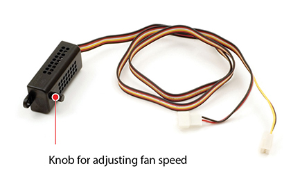
• Figure 7.38 Manual fan adjustment device
Larger fans that spin more slowly are another way to reduce noise while maintaining good airflow. Fans sizes are measured in millimeters (mm) or centimeters (cm). Traditionally, the industry used 80-mm power supply and cooling fans, but today you’ll find 92-mm, 120-mm, 140-mm, and even larger fans in power supplies and cases.
Because the temperature inside a PC changes depending on the load put on the PC, the best solution for noise reduction combines a good set of fans with temperature sensors to speed up or slow down the fans automatically. A PC at rest uses less than half of the power of a PC running a video-intensive computer game and therefore makes a lot less heat. Virtually all modern systems support three fans through three 3-pin fan connectors on the motherboard. The CPU fan uses one of these connectors, and the other two are for system fans or the power supply fan.
Assuming your fans are installed with three-wire connections, you can monitor and control your fans. Before you start messing with fans, keep in mind that on most systems you never have to touch anything in terms of fans because the system and the OS work together to turn them on and off as needed.
Most system setup utilities provide some amount of control over fans plugged into the motherboard. Figure 7.39 shows typical system settings for the fans in system setup.
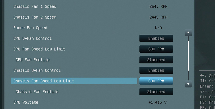
• Figure 7.39 System setup
■ Troubleshooting Power Supplies
Power supplies fail in two ways: sudden death and slowly over time. When they die suddenly, the computer will not start and the fan in the power supply will not turn. In this case, verify that electricity is getting to the power supply before you do anything. Avoid the embarrassment of trying to repair a power supply when the only problem is a bad outlet or an extension cord that is not plugged in. If the system has electricity, the best way to verify that a power supply is working or not working is to use a multimeter to check the voltages coming out of the power supply (see Figure 7.40).

• Figure 7.40 Testing one of the 5-V DC connections
Do not panic if your power supply puts out slightly more or less voltage than its nominal value. The voltages supplied by most PC power supplies can safely vary by as much as ±10 percent of their stated values. This means that the 12.0-V line can vary from roughly 10.8 to 13.2 V without exceeding the tolerance of the various systems in the PC. The 5.0- and 3.3-V lines offer similar tolerances.
Be sure to test every connection on the power supply—that means every connection on your main power as well as every Molex and mini. Because all voltages are between –20 and +20 VDC, simply set the multimeter to the 20-V DC setting for everything. If the power supply fails to provide power, throw it out the window and get a new one—even if you’re a component expert and a whiz with a soldering iron. Don’t waste your time or your company’s time; the price of new power supplies, and the danger of a nasty or even deadly shock, makes replacement the obvious way to go.
No Motherboard
Power supplies will not start unless they’re connected to a motherboard, so what do you do if you don’t have a motherboard you trust to test? First, try an ATX tester. Many companies make these devices. Look for one that supports both 20- and 24-pin motherboard connectors as well as all of the other connectors on your power supply. Figure 7.41 shows a power supply tester.
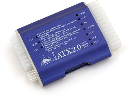
• Figure 7.41 ATX power supply tester
When Power Supplies Die Slowly
If all power supplies died suddenly, this would be a much shorter chapter. Unfortunately, the majority of PC problems occur when power supplies die slowly over time. This means that one of the internal electronics of the power supply has begun to fail. The failures are always intermittent and tend to cause some of the most difficult to diagnose problems in PC repair. The secret to discovering that a power supply is dying lies in one word: intermittent. Whenever you experience intermittent problems, your first guess should be that the power supply is bad. Here are some other clues you may hear from users:
■ “Whenever I start my computer in the morning, it starts to boot, and then locks up. If I press CTRL-ALT-DEL two or three times, it will boot up fine.”
■ “Sometimes when I start my PC, I get an error code. If I reboot, it goes away. Sometimes I get different errors.”
■ “My computer will run fine for an hour or so. Then it locks up, sometimes once or twice an hour.”
■ “It takes a couple of tries—plugging and unplugging—with a new USB device before my system recognizes it.”
Sometimes something bad happens and sometimes it does not. That’s the clue for replacing the power supply. And don’t bother with the multimeter; the voltages will show up within tolerances, but only once in a while they will spike and sag (far more quickly than your multimeter can measure) and cause these intermittent errors. When in doubt, change the power supply. Power supplies break in computers more often than any other part of the PC except components with moving parts. You might choose to keep extra power supplies on hand for swapping and testing.
Fuses and Fire
Inside every power supply resides a simple fuse. If your power supply simply pops and stops working, you might be tempted to go inside the power supply and check the fuse. This is not a good idea. First off, the capacitors in most power supplies carry high-voltage charges that can hurt a lot if you touch them. Second, fuses blow for a reason. If a power supply is malfunctioning inside, you want that fuse to blow because the alternative is much less desirable.
Failure to respect the power of electricity will eventually result in the most catastrophic of all situations: an electrical fire. Don’t think it can’t happen to you! Keep a fire extinguisher handy. Every computer workbench needs a fire extinguisher, but make sure you have the right one. The fire prevention industry has divided fire extinguishers into five fire classes:
■ Class A Ordinary free-burning combustible, such as wood or paper
■ Class B Flammable liquids, such as gasoline, solvents, or paint
■ Class C Live electrical equipment
■ Class D Combustible metals such as titanium or magnesium
■ Class K Cooking oils, trans-fats, or fats
As you might expect, you should use only a Class C fire extinguisher on a burning computing device. All fire extinguishers are required to have their type labeled prominently on them. Many fire extinguishers are multiclass in that they can handle more than one type of fire. The most common fire extinguisher is type ABC—it works on all common types of fires, though it can leave residue on computing equipment.
Redundant Power Supplies
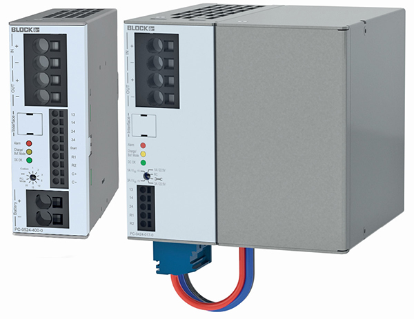
Two is always better than one! You will never have to worry about power failure when you have a redundant power supply (RPS), which is where two identical RPS power supplies are used in a server (see Figure 7.42). When both power supplies are in use by the host computer and the electrical load is between them, this is known as load balancing. So, for example, if the computer needs 500 watts, both power supplies will provide 250 watts, but if one fails, the other can then jump up to giving the whole 500 watts.
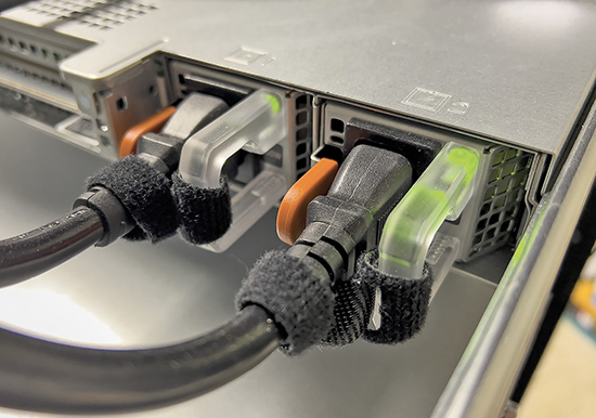
• Figure 7.42 Redundant power supply
Modular Power Supplies
It’s getting more and more popular to make PCs look good on both the inside and the outside. Unused power cables dangling around inside PCs create a not-so-pretty picture and can impede airflow. To help stylish people, manufacturers created modular power supplies. (see Figure 7.43).
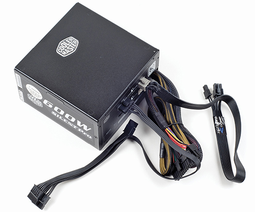
• Figure 7.43 Modular power supply
Modular cables are cool! You add only the lines you need for your system. On the other hand, some techs claim that modular cables hurt efficiency because the modular connectors add resistance to the lines. You make the choice: Is a slight reduction in efficiency worth a clean look?
Chapter 7 Review
■ Chapter Summary
After reading this chapter and completing the exercises, you should understand the following about power supplies.
Explain the basics of electricity
■ The power supply unit (PSU) takes electricity from the wall outlet and transforms it into the kind of electricity that the motherboard and other internal components use. To remove the power supply, unscrew the four screws in the back of the case and lift it out. Installing it is just as simple. Be careful never to open the power supply itself, as the capacitors inside can store a dangerous electrical charge.
■ Techs need to know basic principles of electricity and how to recognize power problems. Electricity is a flow of negatively charged particles (electrons) through matter. Metallic wire is a good conductor, allowing electrons to move freely. The pressure of the electrons in the wire is called voltage and is measured in volts (V). Measured in units called amperes (amps or A), current (or amperage) is the number of electrons moving past a certain point on a wire. Wattage (watts or W) refers to the amount of amps and volts a particular device needs. The formula VA = W expresses the correlation among the three. Resistance to the flow of electrons is measured in ohms (Ω). Fuses and ground wires set limits for the flow of electrons. A ground wire provides a path of least resistance to allow the electrons to flow to the ground.
■ Electricity may be either direct current (DC), with electrons flowing in one direction around a continuous circuit, or alternating current (AC), with electrons flowing back and forth in a circuit.
Describe the details of powering the PC
■ Because power companies supply high-voltage AC, the computer’s power supply converts AC to low-voltage DC that is then portioned out to the internal devices. Heat is a byproduct of electricity and must be controlled in the computer.
■ The power supply connects to the electrical outlet via a standard IEC-320 connector. Although power in the United States ranges from 110 to 120 V, the rest of the world uses 220 to 240 VAC. Most power supplies can switch between 115 and 230 V. The IEC-320 plug has three holes, called hot, neutral, and ground. The hot carries electrical voltage and should output approximately 115 V in the United States. The neutral returns electricity to the breaker panel and should have 0 V output. The ground wire returns excess electricity to the ground and should also have 0 V output. You can use a multimeter to test voltages at the outlet.
■ A multimeter, also called a volt-ohm meter (VOM), uses two probes to provide at least four measurements: AC voltage (V~), DC voltage (V with a solid line above a dashed line), continuity (whether electrons flow from one end of a wire to the other end), and resistance (whether a fuse is good or blown or whether a wire has breaks). Some AC-only testing devices are available that simply plug into the AC outlet and may display results via three LEDs.
■ A surge suppressor is an inexpensive device that protects a computer from voltage spikes. Inserted between the wall outlet and the power supply, a surge suppressor has a joule rating that measures how much electrical energy it can suppress. Be sure your surge suppressor has at least a 2000 joules rating. Because telephone lines and cable connections also produce spikes, your surge suppressor should include connections for a modem, DSL, or cable modem. Make sure you purchase a surge suppressor that has the UL 1449 for 330-V rating, as this will ensure substantial protection for your system. Because surge suppressors work for only a limited time, you should check the manufacturer’s recommended replacement schedules. If your surge suppressor comes with a cash guarantee against system failure due to surges, be aware that manufacturers honor it only if you follow their guidelines.
■ Because the AC supply lacks consistency and actually provides power with sags and spikes, it is important that you use two devices with a computer: an uninterruptible power supply and a surge suppressor. An uninterruptible power supply (UPS) continues to supply AC power to your computer during both brownouts and blackouts via a battery that is charged from the AC current. All UPSs measure the amount of power (watts) they supply, as well as listing the number of minutes the UPS will last with a certain voltage. It’s difficult to estimate exactly how much wattage your computer and devices will require, so the better method to determine the UPS you need is to go to the UPS makers’ Web sites and use their power calculators.
■ The power supply converts AC into several DC voltages (5.0, 12.0, and 3.3 V). Devices such as hard drives and optical drives require 12 V, and onboard electronics use 3.3- and 5-V currents.
■ The power supply has several standard connectors for the motherboard and interior devices. Today’s motherboards have a P1 socket that uses the P1 connector from the power supply. A standard ATX power supply has a 20-pin P1 connector, while the newer ATX12V 2.0 power supplies come with a 24-pin P1 connector. Some motherboards also need a 4-, 6-, or 8-pin connector to provide an additional 12 V of power.
■ Peripherals use two or possibly three different kinds of connectors: the larger Molex connector, the smaller mini connector, and the SATA connector. Used with hard drives and optical drives, the Molex has chamfers to ensure that it is connected properly. Used rarely today, the mini/Berg connector can easily be inserted incorrectly, thus destroying the device. The SATA connector is used for SATA drives. If you do not have enough connectors for all of the devices inside your PC, you can create more connections with a splitter. Similarly, if your power supply does not have the connector a device needs, you can purchase adapters to convert one type to another.
■ The ATX power supply includes full support for power-saving functions and waking from sleep due to incoming network traffic. Using the soft power feature, the ATX power supply puts a 5-V charge on the motherboard as long as there is AC from the wall socket. You can configure the ATX soft power through the Power Management section of the CMOS setup. Always unplug an ATX system before you work on it. ATX power supplies use a single P1 connector for motherboard power.
■ The ATX standard has undergone several updates. ATX12V 1.3 introduced additional 4-pin (P4) and 6-pin auxiliary (AUX) connectors. ATX12V 2.0 introduced the 24-pin connector (inspired by EPS12V), dropped the AUX connector, and required SATA connectors. Additionally, ATX12V 2.0 requires two 12-V rails for any power supply rated higher than 230 W.
■ The non-ATX standard EPS12V introduced a 24-pin motherboard connector and a unique 8-pin connector. It was not swappable with ATX power supplies, and while its popularity was short-lived, it introduced several features that became part of the ATX12V standard, including rails.
■ Higher-performing motherboard/CPU combinations and video cards require additional power, sometimes through a Molex connector. High-end video cards will use one or two PCIe connectors of 6 or 8 pins.
■ The demand for smaller and quieter PCs led to the development of niche-market power supply form factors. Mini-ITX, microATX, TFX12V, SFX12V, CFX12V, and LFX12V have the same connectors as standard ATX power supplies but differ in size or shape.
■ Active power factor correction (active PFC) helps to eliminate harmonics, which can damage electrical components. Never buy a power supply that does not have active PFC.
■ Power supplies are rated in watts. If you know the wattage every device in the PC needs, you can arrive at the total wattage required for all devices, and that is the minimum wattage your power supply should provide. If the power supply does not provide sufficient wattage, the computer will not work. For a new computer system, you should select at least a 550-W power supply to have extra power for adding components in the future.
■ Because converting from AC to DC may result in a significant loss of wattage, purchase a power supply that offers a high percentage of efficiency. The ATX12V 2.0 standard requires a power supply to be at least 70 percent efficient, but you can find power supplies with better than 80 percent efficiency. Look for the 80 Plus rating to find the most efficient power supplies. Be aware that power supplies produce less wattage over time, so don’t cut the wattage specification too tightly. While power supplies range from 200 to 1000 W and higher, you should know that the more AC the power supply draws, the more heat it produces.
Install and maintain power supplies
■ Power supplies connect to the PC case via four screws mounted in the rear of the case. Unscrew the four screws and the power supply will lift out. Because an ATX power supply is always on, be sure to unplug it from the wall outlet before working on it.
■ Adequate cooling is important to prevent damage to the computer’s internal components. The fan inside the power supply itself cools the voltage regulator circuits within the power supply and provides a constant flow of outside air throughout the interior of the computer case. If the fan is not working, turn the computer off before you experience equipment failure. Some power supplies regulate airflow by using a sensor.
■ To improve cooling, most cases come with a case fan. If the case does not have one, you should add one. Case fans may use standard Molex connectors or a special three-pronged power connector that plugs directly into the motherboard. To enable the fans to create airflow, the case needs to be closed. If slot covers are left off of empty expansion bays, the computer can overheat. Slot covers also help keep dust and smoke out of the case. Beware of “great deals” on cases that come with power supplies, because the included power supply is often substandard.
■ Electrical problems range from irregular AC to dying or faulty power supplies. Power supplies may fail suddenly or slowly over time. After you make sure that the wall outlet is providing electricity, checking voltages from the power supply with a multimeter is the best way to verify that the power supply is working or has failed. A power supply is functioning properly if the output voltages are within 10 percent over or under the expected voltage. Be sure to check all of the connections on the power supply. If you determine that the power supply is bad, the most economical solution is to replace it with a new one.
■ Power supplies will not start unless they are connected to a motherboard. If you need to test a power supply but don’t have a motherboard, use an ATX tester.
Explain power supply troubleshooting and fire safety
■ If one of the internal electrical components in the power supply begins to fail, the result is usually intermittent problems, making diagnosis difficult. If you are experiencing intermittent problems, such as lockups or different error codes that disappear after rebooting, suspect the power supply. Unfortunately, the multimeter is not good for diagnosing intermittent problems. Power supplies fail almost as often as optical drives and hard drives, so it is a good idea to keep power supplies in stock for swapping and testing.
■ Never open a power supply, even to check the fuse; the unit contains capacitors that carry high-voltage charges that can hurt you.
■ Every computer workbench should have a Class C fire extinguisher handy in case of an electrical fire.
■ Key Terms
active power factor correction (active PFC)
alternating current (AC)
amperage
amperes (amps or A)
battery backup
blackouts
brownouts
current
direct current (DC)
dual voltage
IEC-320
joule
mini connector
Molex connector
multimeter
multi-rail
ohms (Ω)
P1 power connector
P4 power connector
PCIe 6/8-pin power connector
power conditioning
power supply fan
power supply unit (PSU)
rails
resistance
SATA power connector
single rail
slot covers
soft power
surge suppressor
volts (V)
wattage (watts or W)
wattage rating
■ Key Term Quiz
Use the Key Terms list to complete the sentences that follow. Not all terms will be used.
1. Better video cards use one (or two) __________________ from the power supply.
2. The electric company provides __________________ power that the power supply converts to __________________ for use by the computer components.
3. If the __________________ are left off the expansion slots, the computer may overheat.
4. An ATX form factor power supply attaches to the motherboard with a(n) __________________ and a P4 connector and supplies 5 V to the motherboard at all times.
5. Be sure your surge suppressor has a(n) __________________ rating of at least 2000.
6. The measurement unit for the number of electrons moving past a certain point on a wire is __________________.
7. The __________________ provides the basic cooling for the PC.
8. Be sure the __________________ rating for your power supply is greater than the minimum required by all devices in the computer.
9. The ability to split voltage supplies into separate __________________ ensures that no device will hog all of the available power.
10. Large sags in electricity are also known as ____________________.
■ Multiple-Choice Quiz
1. Which of the following ATX12V features was introduced as part of the EPS12V standard?
A. The P4 motherboard power connector
B. Voltage rails
C. The 6-pin AUX connector
D. Soft power
2. Which kind of fire extinguisher should you use for computer equipment?
A. Class A
B. Class B
C. Class C
D. Class D
3. Under what conditions should a PC technician work inside the power supply?
A. Only when it is unplugged.
B. Only when the technician is wearing an antistatic wrist strap.
C. Anytime, because the power supply only has low-energy DC electricity that will not hurt the technician.
D. Never, because the power supply has capacitors that hold electrical charges that may harm the technician.
4. What should you check first if a computer will not start and the fan in the power supply will not turn?
A. The voltages coming out of the power supply
B. The motherboard power connector
C. The power coming into the power supply
D. The power switch
5. When you test voltage with a multimeter, you can assume the outlet or connector is functioning properly if the reading is within a certain percentage of the expected number. What is that maximum percentage by which the reading can vary?
A. 5 percent
B. 10 percent
C. 20 percent
D. 25 percent
6. What voltage does an ATX12V P4 connector provide for motherboards?
A. 3.3 V
B. 3.3 V, 5 V
C. 5 V
D. 12 V
7. When testing an AC outlet, what voltage should the multimeter show between the neutral and ground wires?
A. 120 V
B. 60 V
C. 0 V
D. –120 V
8. What sort of power connector does a traditional hard drive typically use?
A. Molex
B. Mini
C. Sub-mini
D. Micro
9. Arthur installed a new motherboard in his case and connected the ATX power, but his system would not turn on. He sees an extra four-wire port on the motherboard. What’s he missing?
A. He needs to plug in the P2 connector for powering auxiliary components.
B. He needs to plug in the P3 connector to power the case fans.
C. He needs to plug in the P4 connector to power the processor.
D. He needs to plug in the Aux connector to connect to a secondary power supply.
10. What is the effect of exceeding the wattage capabilities of a power supply by inserting too many devices?
A. The system will boot normally, but some of the devices will not function properly.
B. The system will boot normally, and all of the devices will work, but only for a limited time. After an hour or so, the system will spontaneously shut down.
C. The system will not boot or turn on at all.
D. The system will try to boot, but the overloaded power supply will fail, burning up delicate internal capacitors.
11. Where do you put the multimeter leads when you test a Molex connector?
A. The red lead should always touch the red wire; the black lead should touch a black ground wire.
B. The red lead should always touch the black ground wire; the black lead should always touch the red-hot wire.
C. The red lead should always touch the yellow hot wire; the black lead should touch the red-hot wire.
D. The red lead should touch either the red or yellow hot wire; the black lead should touch a black ground wire.
12. Which of the following problems points to a dying power supply?
A. Intermittent lock-ups at boot-up
B. A power supply fan that does not turn
C. A multimeter reading of 11 V for the 12-V power line
D. A computer that won’t start by shorting the soft power jumpers
13. What is the minimum PSU required for an ATX system that requires Molex, mini, and SATA connectors?
A. ATX
B. ATX12V 1.3
C. ATX12V 2.0
D. EPS12V
14. Which of the following is not a PSU form factor?
A. TFX12V
B. SFX12V
C. CFX12V
D. LPX12V
15. Which statement is true?
A. Removing the expansion slot covers on the back of your case will improve cooling by allowing hot air to escape.
B. Shop around when purchasing a case; you will often find good deals that include a powerful PSU.
C. Always keep the power supply plugged in to the wall outlet when working on the inside of a computer, as this helps to ground it.
D. If your power supply fails, don’t try to repair it; buy a new one.
■ Essay Quiz
1. Jack and Denise have joined your study group. Because neither has any previous experience with basic electricity and its jargon, they want you to explain voltage, amperage, and wattage. In plain language, define these terms and explain what VA = W means.
2. In the computer field, advances in one area often lead to advances in another area. Do you think improvements in the CPU and other computer devices and functions made the ATX form factor power supply necessary? Explain your response.
3. Because microprocessors have become more powerful and more devices have been invented for the computer, the wattage demands for the PC have gone up. So has the need for cooling. Discuss the cooling devices that come with today’s PCs and what the user needs to know about keeping the PC cool.
4. Helene’s computer worked fine last week. Although she has not changed anything since then, today her computer won’t even boot. You suspect that the power supply died. You know she does not have a multimeter. What will you tell her to check to confirm this opinion? If she does need to replace the power supply, how can she be sure the new one will work with her PC?
Lab Projects
• Lab Project 7.1
This chapter recommends a 550-W power supply (at least) for a new computer. Is that the wattage that manufacturers usually offer with their computers? Check the following Web sites to see what wattage comes with a new PC:
Do any of these companies mention a power supply upgrade with a higher wattage rating? If so, what are the wattages and what are the additional costs?
• Lab Project 7.2
Every technician needs a multimeter. Visit a local electronics store and look at its line of multimeters. (If a store is not nearby, you may use the Internet instead.) What features do the various multimeters offer? What kinds of measurements do they provide? Is the output from some in digital format and others in analog? Which output do you find easier to read? Is one kind more accurate than another? What price ranges are available for multimeters? Then, select the multimeter you would like to add to your toolkit. Why did you choose that model? Now start saving your pennies so you can buy it!