chapter 6
Motherboards
“Did anybody hear that?”
—MICHAEL “MOTHERBOARD” PAMPIN, RAINBOW SIX: VEGAS

In this chapter, you will learn how to
■ Explain how motherboards work
■ Recognize modern expansion buses
■ Upgrade and install motherboards
■ Troubleshoot motherboard problems
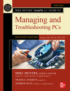
The motherboard provides the foundation for the personal computer. Every piece of hardware, from the CPU to the lowliest expansion card, directly or indirectly plugs into the motherboard. The motherboard contains the wires—called traces—that make up the buses of the system. It holds the vast majority of the ports used by the peripherals, and it distributes the power from the power supply (see Figure 6.1). Without the motherboard, you literally have no PC.
• Figure 6.1 Traces visible beneath the CPU socket on a motherboard
This chapter starts with an explanation of how motherboards work, identifying various types or form factors of motherboards, including distinguishing features. The second section examines expansion capabilities on motherboards, specifically the types of expansion slots you’ll run into in the wild, and how to install expansion cards. The third section goes through the pragmatic steps of upgrading and installing motherboards. The chapter finishes with techniques for troubleshooting motherboard problems.
Historical/Conceptual
■ How Motherboards Work
Three variable and interrelated characteristics define modern motherboards: form factor, chipset, and components. The form factor determines the physical size of the motherboard as well as the general location of components and ports. The chipset defines the type of processor and RAM the motherboard requires and determines to a degree the built-in devices the motherboard supports, including the expansion slots. Finally, the built-in components determine the core functionality of the system.
 Tech Tip
Layers of the PCB
Modern motherboards are layered printed circuit boards (PCBs), copper etched onto a nonconductive material and then coated with some sort of epoxy for strength. The layers mask some of their complexity. You can see some of the traces on the board, but every motherboard is four or more layers thick. The layers contain a veritable highway of wires, carrying data and commands back and forth between the CPU, RAM, and peripherals.
The layered structure enables multiple wires to send data without their signals interfering with each other. The layered approach allows the manufacturer to add complexity and additional components to the board without extending the overall length and width of the board. Shorter traces also allow signals to travel faster than they would if the wires were longer, as would be necessary if motherboards did not use layers. The multiple layers also add strength to the board itself, so it doesn’t bend easily.
Almost all chipsets used in desktops and laptops are made by either Intel or AMD. It’s fitting that the two biggest CPU manufacturers for Windows-, macOS-, and Linux-based computers would also produce the essential supporting chipsets.
Any good tech should be able to make a recommendation to a client about a particular motherboard simply by perusing the specs. Because the motherboard determines function, expansion, and stability for the whole PC, it’s essential that you know your motherboards!

Form Factors
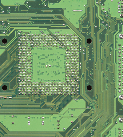
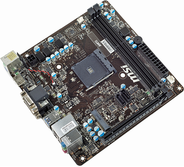
Motherboard form factors are industry-standardized shapes and layouts that enable motherboards to work with cases and power supplies. A single form factor applies to all three components. All motherboards come in a basic rectangular or square shape but vary in overall size and in the layout of built-in components (see Figure 6.2). You need to install a motherboard in a case designed to fit it, so the ports and slot openings on the back fit correctly.
• Figure 6.2 Typical motherboard
The power supply and the motherboard need matching connectors, and different form factors define different connections. Given that the term “form factor” applies to the case, motherboard, and power supply—the three parts of the PC most responsible for moving air around inside the PC—the form factor also defines how the air moves around in the case.
To perform motherboard upgrades and provide knowledgeable recommendations to clients, techs need to know their form factors. The PC industry has adopted—and dropped—a number of form factors over the years with such names as AT, ATX, and ITX. Let’s start with the granddaddy of all PC form factors, AT.

AT Form Factor
The AT form factor (see Figure 6.3), invented by IBM in the early 1980s, was the predominant form factor for motherboards through the mid-1990s. AT is now obsolete.

• Figure 6.3 AT-style motherboard
The AT motherboard had a few size variations (see Figure 6.4), ranging from large to very large. The original AT motherboard was huge, around 12 inches wide by 13 inches deep. PC technology was new and needed lots of space for the various chips necessary to run the components of the PC.

• Figure 6.4 AT motherboard (bottom) and Baby AT motherboard (top)
The single greatest problem with AT motherboards was the lack of external ports. When PCs were first invented, the only devices plugged into the average PC were a monitor and a keyboard. That’s what the AT was designed to handle—the only dedicated connector on an AT motherboard was the keyboard port (see Figure 6.5).

• Figure 6.5 Keyboard connector on the back of an AT motherboard
Over the years, the number of devices plugged into the back of the PC has grown tremendously. Your average PC today has a keyboard, a mouse, a printer, some speakers, a monitor, and—if your system’s like mine—four to six USB devices connected to it at any given time. These added components created a demand for a new type of form factor, one with more dedicated connectors for more devices. Many attempts were made to create a new standard form factor. Invariably, these new form factors integrated dedicated connectors for at least the mouse and printer, and many even added connectors for video, sound, and phone lines.
1101
ATX Form Factor
There continued to be a tremendous demand for a new form factor, one that had more standard connectors and also was flexible enough for possible changes in technology. This demand led to the creation of the ATX form factor in 1995 (see Figure 6.6). ATX got off to a slow start, but by around 1998, ATX overtook AT to become the most common form factor, a distinction it holds over 20 years later.

• Figure 6.6 Early ATX motherboard
ATX is distinct from AT in the lack of an AT keyboard port, replaced with a rear panel that has all necessary ports built in. Note the mini-DIN (PS/2) keyboard and mouse ports at the left of Figure 6.7, standard features on some ATX boards. You recall those from Chapter 2, right?

• Figure 6.7 ATX ports
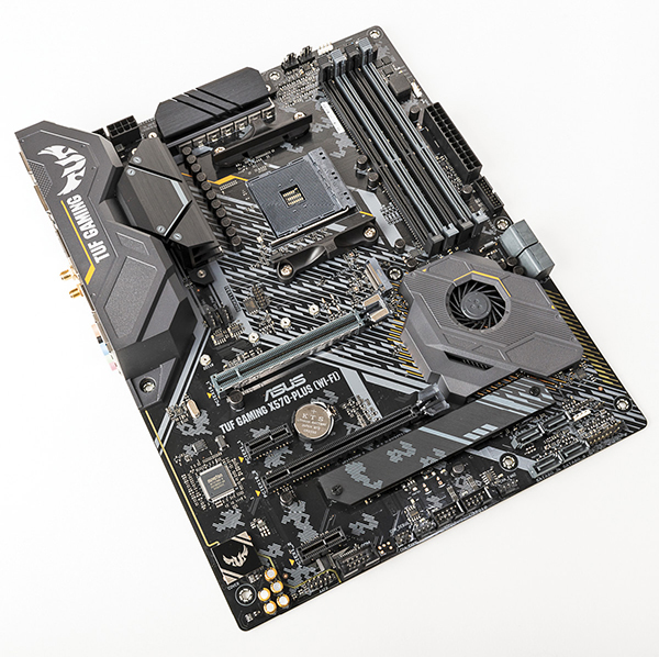
The ATX form factor includes many improvements over AT. The position of the power supply creates better air movement. The CPU and RAM are placed to provide easier access, and the rearrangement of components prevents long expansion cards from colliding with the CPU or northbridge. Other improvements, such as placing the RAM closer to the northbridge and CPU than on AT boards, offer users enhanced performance as well. The shorter the wires, the easier to shield them and make them capable of handling double or quadruple the clock speed of the motherboard. Figure 6.8 shows AT and ATX motherboards—note the radical differences in placement of internal connections.
• Figure 6.8 AT (left) and ATX (right) motherboards for quick visual comparison
ATX motherboards come in three variations to accommodate different types of cases. So far, you’ve seen the full-sized ATX form factor, which is 12 by 9.6 inches.
 Cross Check
High-Speed CPUs and RAM
Modern CPUs incorporate the memory controller on the processor rather than locating it on the chipset. This move has facilitated even further increases in the speed at which the processor can fetch data from RAM. Refer to Chapters 3 and 4 and see if you can answer these questions.
1. What different clock frequencies are supported by DDR4 and DDR5 types of memory?
2. What processors support DDR5 memory?
The microATX motherboard (see Figure 6.9) floats in at a svelte 9.6 by 9.6 inches (usually), or about 30 percent smaller than standard ATX, yet uses the standard ATX connections. A microATX motherboard fits into a standard ATX case or in the much smaller microATX cases. Note that not all microATX motherboards have the same physical size. You’ll sometimes see microATX motherboards referred to with the Greek symbol for micro, as in µATX.

• Figure 6.9 A microATX motherboard
ITX
VIA Technologies started the process to create a small form factor (SFF) motherboard, the Information Technology eXtended, or ITX. The ITX itself wasn’t a success, but VIA in turn created smaller form factors that today populate the SFF market, specifically Mini-ITX.
Mini-ITX (see Figure 6.10) is a miniscule 6.7 by 6.7 inches and competes head to head with the virtually identical microATX.
• Figure 6.10 A Mini-ITX motherboard
One of the great benefits of these SFF motherboards is the tiny amount of power needed to support them. ITX power supplies are quite small compared to a typical power supply. Lower power usage produces less heat, thus enabling passive cooling on many SFF systems. The lack of fan noise makes them ideal for media center PCs.
Proprietary Form Factors
Several major PC makers make motherboards that work only with their cases. These proprietary motherboards enable these companies to create systems that stand out from the generic ones and, not coincidently, push you to get service and upgrades from their authorized dealers. Some of the features you’ll see in proprietary systems are riser cards (also known as daughter boards)—part of a motherboard separate from the main one but connected by a cable of some sort—and unique power connections.
 Try This!
Motherboard Varieties
Motherboards come in a wide variety of form factors. Go to your local computer store and check out what is on display. Note the different features offered by ATX, microATX, and Mini-ITX motherboards.
1. ATX is common, but does the store stock Mini-ITX or proprietary motherboards?
2. Did the clerk use tech slang and call the motherboards “mobos”? (It’s what most of us call them outside of formal textbooks, after all!)
Chipset
You learned in the previous chapter that every motherboard has a chipset, one or more discrete integrated circuit chips that support the CPU’s interfacing to all the other devices on the motherboard. The chipset determines the type of processor the motherboard accepts, the type and capacity of RAM, and the sort of internal and external devices that the motherboard supports. Chipsets vary in features, performance, and stability, so they factor hugely in the purchase or recommendation of a particular motherboard. Good techs know their chipsets!
Because the chipset facilitates communication between the CPU and other devices in the system, its component chips are relatively centrally located on the motherboard (see Figure 6.11). As you’ll recall from Chapter 5, chipsets were originally composed of two primary chips: the northbridge and the southbridge.
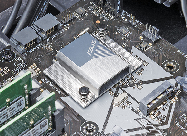
• Figure 6.11 Chipset hidden under cooling fins on modern motherboards
The northbridge chip handled RAM, while the southbridge handled some expansion devices and mass storage drives, such as hard drives. Some motherboard manufacturers added (or still add) a third chip called the Super I/O chip to handle these chores, especially in dealing with legacy devices. Figure 6.12 shows a typical Super I/O chip.

• Figure 6.12 Super I/O chip on ASUS motherboard
Today, other chips have absorbed many of the functions of the classic chipset. The CPU handles the memory controller features the northbridge used to do. The primary expansion bus communication (see “Expansion Bus” later in this chapter) goes through the CPU as well, something the southbridge handled back in the day. Most techs refer to the remaining support chips on the motherboard as the chipset, although the terms northbridge and southbridge are dead.
The system ROM chip provides part of the BIOS for the chipset, but only at a barebones, generic level. The chipset still needs support for the rest of the things it can do. So how do expansion devices get BIOS? From software drivers, of course, and the same holds true for modern chipsets. You have to load the proper drivers for the specific OS to support all of the features of today’s chipsets. Without software drivers, you’ll never create a stable, fully functional PC. Most motherboards ship with an optical disc with drivers, support programs, and extra-special goodies such as antivirus software (see Figure 6.13).

• Figure 6.13 Driver disc for ASUS motherboard
Different chipsets offer support for a lot of different hardware options, including type of memory slot (DDR4 or DDR5), number and version of USB ports, various mass storage devices, integrated network connections, video support, and so on. Figure 6.14 shows a schematic with typical chipset chores for an Intel Z690 chipset.

• Figure 6.14 Schematic of a chipset
Good techs need to know the hot chipsets in detail. The chipset defines almost every motherboard feature short of the CPU itself. Techs love to discuss chipsets and expect a fellow tech to know the differences between one chipset and another. You also need to be able to recommend a motherboard that suits a client’s needs. Chapter 11 covers choosing components and building PCs for specific purposes, such as video editing and gaming. One of the most important choices you’ll make in building a custom rig is selecting a chipset.
Standard Components
Every motherboard provides a socket (or two) for a CPU and slots for RAM. I already covered the variety of both sockets (in Chapter 3) and slot types (in Chapter 4), so I won’t rehash them here. You’ll also find ports to support standard mass storage devices, such as hard drives and solid-state drives (covered in more detail in Chapter 8).
Additional Components
The connections and capabilities of a motherboard sometimes differ from those of the chipset the motherboard uses. This disparity happens for a couple of reasons. First, a particular chipset may support eight USB ports, but to keep costs down, the manufacturer might include only four ports. Second, a motherboard maker may choose to install extra features—ones not supported by the chipset—by adding additional chips. A common example is a motherboard that supports an old serial port. Other technologies you might find are built-in sound, hard drive RAID controllers, network cards, and more. Some motherboards have added convenience features, such as case fan power connectors and running lights so you can see what you’re working on.
USB
All chipsets support USB, but it seems no two motherboards offer the same port arrangement. My motherboard supports eight USB ports, for example, but if you look on the back of the motherboard, you’ll only see four USB ports (see Figure 6.15).

• Figure 6.15 USB connectors showing on back of PC
Most motherboards have headers—internal connectors—to plug in header cables for additional external ports. These headers are standardized, so many cases have built-in front USB ports that have header cables attached (see Figure 6.16). This is very handy for USB devices you might want to plug and unplug frequently, such as thumb drives or digital cameras.

• Figure 6.16 Front USB connections
Sound
Most motherboards come with onboard sound support. As with USB, a lot of motherboards have a port for connecting to audio jacks on the front of the case, another example (like USB) of front panel connectors. These enable you to plug headphones or microphones into the front rather than the rear of the case, a very convenient feature. These connectors are identical to the ones used on sound cards, so we’ll save more discussion for Chapter 10.
Networking
Most desktop motherboards come with at least one RJ-45 jack for attaching a network cable. The networking support is built into the chipset or comes as an additional chip soldered to the motherboard. Chapter 18 covers the physical aspects of networking in detail.
Video
Many motherboards sport one or more video ports for attaching a display. These vary a lot, from the venerable VGA to the HDMI and DisplayPort that are common today. Chapter 17 discusses video in depth, so we’ll save further discussion until then.
RAID
RAID stands for redundant array of independent (or inexpensive) disks and is very common on motherboards. There are many types of RAID, such as mirroring (the process of using two drives to hold the same data, which is good for safety, because if one drive dies, the other still has all of the data) or striping (making two drives act as one drive by spreading data across them, which is good for speed). RAID is a very cool but complex topic that’s discussed in detail in Chapter 8.
Case Fan Support
Every motherboard has a CPU fan power connector, as you’ll recall from Chapter 3, usually a four-wire connector that supports three-wire fans too. Some motherboards offer one or more fan power connectors for case fans. These are almost always only three-wire connectors. The case fans plugged into the motherboard can be monitored and controlled in Windows, unlike case fans connected only to the power supply, so they add a nice feature.
■ Expansion Bus
Expansion slots have been part of the PC from the very beginning. Way back then, IBM created the PC with an eye to the future; the original IBM PC had slots built into the motherboard—called expansion slots—for adding expansion cards and thus new functions to the PC. (Specific expansion cards such as video, sound, capture, and NIC are discussed later in Chapter 17.) The slots and accompanying wires and support chips on the first PC and on the latest and greatest PC are called the expansion bus.
Structure and Function of the Expansion Bus
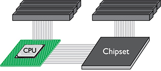
As you’ve learned, every device in the computer—whether soldered to the motherboard or snapped into a socket—connects to the external data bus and the address bus. The expansion slots are no exception. They connect to the rest of the PC through the chipset. Exactly where on the chipset varies depending on the system. On newer systems, the expansion slots connect to the CPU (see Figure 6.17) because modern CPUs contain a lot of controller features that used to be in the chipset. In older systems, the expansion slots connected directly to the chipset (see Figure 6.18). Finally, many systems have more than one type of expansion bus, with slots of one type connecting to the CPU and slots of another type connecting to the chipset (see Figure 6.19).

• Figure 6.17 Expansion slots connecting to CPU

• Figure 6.18 Expansion slots connecting to chipset
• Figure 6.19 Expansion slots connecting to both CPU and chipset
The chipset provides an extension of the address bus and data bus to the expansion slots, and thus to any expansion cards in those slots. If you plug a hard drive controller card into an expansion slot, it functions just as if it were built into the motherboard, albeit with one big difference: speed. As you’ll recall from Chapter 3, the system crystal—the clock—pushes the CPU. The system crystal provides a critical function for the entire PC, acting like a drill sergeant calling a cadence, setting the pace of activity in the computer. Every device soldered to the motherboard is designed to run at the speed of the system crystal. A 200-MHz motherboard, for example, has its chipset chips all timed by a 200-MHz crystal (see Figure 6.20).
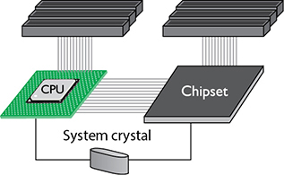
• Figure 6.20 The system crystal sets the speed.
Clock crystals aren’t just for CPUs and chipsets. Pretty much every chip in your computer has a CLK wire and needs to be pushed by a clock chip, including the chips on your expansion cards. Suppose you buy a device that did not come with your computer—say, a graphics card. The chips on the graphics card need to be pushed by a CLK signal from a crystal. If PCs were designed to use the system crystal to push that graphics card, graphics card manufacturers would need to make graphics cards for every possible motherboard speed. You would have to buy a 100-MHz graphics card for a 100-MHz system or a 200-MHz graphics card for a 200-MHz system.
That would be ridiculous, and IBM knew it when they designed the PC. They had to make an extension to the external data bus that ran at its own standardized speed. You would use this part of the external data bus to snap new devices into the PC. IBM achieved this goal by adding a different crystal, called the expansion bus crystal, which controlled the part of the external data bus connected to the expansion slots (see Figure 6.21).

• Figure 6.21 Function of system and expansion bus crystals
The expansion slots run at a much slower speed than the frontside bus. The chipset acts as the divider between the two buses, compensating for the speed difference with wait states and special buffering (storage) areas. No matter how fast the motherboard runs, the expansion slots run at a standard speed. In the original IBM PC, that speed was about 14.318 MHz ÷ 2, or about 7.16 MHz. Luckily, modern expansion buses run much faster! Let’s start with the oldest of the modern expansion slots, PCI.
PCI
Intel introduced the Peripheral Component Interconnect (PCI) bus architecture (see Figure 6.22) in the early 1990s, and the PC expansion bus was never again the same. Intel made many smart moves with PCI, not the least of which was releasing PCI to the public domain to make PCI very attractive to manufacturers. PCI provided a wider, faster, more flexible alternative than any previous expansion bus. The exceptional technology of the new bus, combined with the lack of a price tag, made manufacturers quickly drop older buses and adopt PCI.
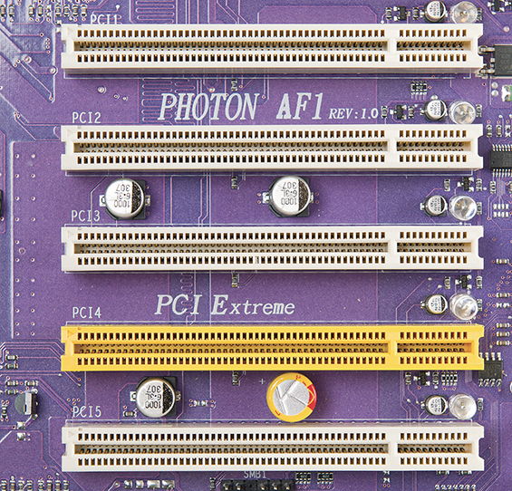
• Figure 6.22 PCI expansion bus slots
PCI really shook up the PC world with its capabilities. The original PCI bus was 32 bits wide and ran at 33 MHz, which was superb, but these features were expected and not earth-shattering. The coolness of PCI came from its capability to coexist with other expansion buses. When PCI first came out, you could buy a motherboard with both PCI and older slots. This was important because users could keep their old expansion cards and slowly migrate to PCI. Equally impressive was that PCI devices were (and still are) self-configuring, a feature that led to the industry standard that became known as plug and play (PnP). Finally, PCI had a powerful burst-mode feature that enabled very efficient data transfers.
PCI Express
PCI Express (PCIe) is still PCI, but it uses a point-to-point serial connection instead of PCI’s shared parallel communication. Consider a single 32-bit chunk of data moving from a device to the CPU. In PCI parallel communication, 32 wires each carry one bit of that chunk of data. In serial communication, only 1 wire carries those 32 bits. You’d think that 32 wires are better than 1, correct?
First of all, PCIe doesn’t share the bus. A PCIe device has its own direct connection (a point-to-point connection) to the CPU, so it does not wait for other devices. Plus, when you start going really fast (think gigabits per second), getting all 32 bits of data to go from one device to another at the same time is difficult, because some bits get there slightly faster than others. That means you need some serious, high-speed checking of the data when it arrives to verify that it’s all there and in good shape. Serial data doesn’t have this problem, as all of the bits arrive one after the other in a single stream. When data is really going fast, a single point-to-point serial connection is faster than a shared 32-wire parallel connection.
And boy howdy, is PCIe ever fast! A PCIe connection uses one wire for sending and one for receiving. Each of these pairs of wires between a PCIe controller and a device is called a lane. Each direction of a lane runs at 2.5 gigatransfers per second (GTps) with PCIe 1.x, 5 GTps with PCIe 2.x, 8 GTps with PCIe 3.x, and a whopping 16 GTps with PCIe 4.0! Better yet, each point-to-point connection can use 1, 2, 4, 8, 12, or 16 lanes to achieve a maximum theoretical bandwidth of up to 256 GTps. The transfer rate describes the number of operations happening per second. With serial communication, you almost get a one-to-one correlation between transfer rate and binary data rate. The effective data rate drops a little bit because of the encoding scheme—the way the data is broken down and reassembled—but full-duplex data throughput can go up to a whopping 32 GBps on a ×16 connection.
The most common PCIe slot is the 16-lane (×16) version most often used for video cards, as shown in Figure 6.23. The first versions of PCIe motherboards used a combination of a single PCIe ×16 slot and a number of standard PCI slots. (Remember, PCI is designed to work with other expansion slots, even other types of PCI.)
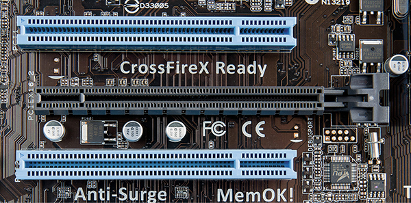
• Figure 6.23 PCIe ×16 slot (center) with PCI slots (top and bottom)
The bandwidth provided by a ×16 slot is far more than anything other than a video card would need, so most PCIe motherboards also contain slots with fewer lanes. Currently ×1 is the most common general-purpose PCIe slot (see Figure 6.24). You’ll also see ×4 slots on some motherboards.
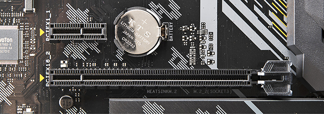
• Figure 6.24 PCIe ×1 slot (top)
Unfortunately for us techs, you can’t always know how fast a PCIe slot is just by its size. Here are a few of the most-common factors that can affect how these slots perform:
■ The slot may be wired for fewer lanes than its size suggests. You will most often see this where a ×16 slot is wired up to only 4 or 8 lanes. If you put a video card that expects 16 lanes in a slot like this, it will work at a fraction of its capacity.
■ Some motherboards don’t have enough lanes for each slot to use its maximum at the same time. In this case, adding expansion cards to a system might slow down already-connected devices.
■ Lower PCIe versions have less bandwidth available—and some motherboards support different PCIe versions on different slots. The CPU you select can also dictate the effective PCIe version.
■ PCIe lanes can be used for some other things on the board as well, and their speed/functionality can be affected by the number of slots/lanes in use (and vice versa). Some examples include network interfaces, newer generations of USB and Thunderbolt, and M.2 (a slot used for high-performance SSDs—we’ll take a closer look at M.2 in Chapter 8).
There’s no great way to just know exactly how each slot will perform. Make sure to check your motherboard manual to understand how many lanes each slot actually supports under different conditions. Don’t go by physical size alone!
Try This!
Shopping Trip
So, what’s the latest PCIe motherboard out there? Get online or go to your local computer store and research higher-end motherboards. What combinations of PCIe slots can you find on a single motherboard? Which motherboard has the most PCIe lanes? Why? Jot them down and compare your findings with your classmates’ findings.
Installing Expansion Cards
Installing an expansion card successfully—another one of those bread-and-butter tasks for the PC tech—requires at least four steps. First, you need to know that the card works with your system and your operating system. Second, you have to insert the card in an expansion slot properly and without damaging the card or the motherboard. Third, you need to provide drivers for the operating system—proper drivers for the specific OS. Fourth, you should always verify that the card functions properly before you walk away from the PC.
Step 1: Knowledge
Learn about the device you plan to install—preferably before you purchase it! Does the device work with your system and operating system? Does it have drivers for your operating system? If you use a recent version of Windows, the answer to these questions is almost always “yes.” If you’re attempting to install an old device or if you’re trying to install a very unique device in a less-common operating system such as Linux, these questions become important. A lot of older hardware simply won’t work with newer versions of Windows, especially Windows 10/11. Check the device’s documentation and check the device manufacturer’s Web site to verify that you have the correct drivers. While you’re checking, make sure you have the latest version of the driver; most devices get driver updates more often than the weather changes in Texas.
Step 2: Physical Installation
To install an expansion card successfully, you need to take steps to avoid damaging the card, the motherboard, or both. This means knowing how to handle a card and avoiding electrostatic discharge (ESD) or any other electrical issue. You also need to place the card firmly and completely into an available expansion slot.
Optimally, a card should always be in one of two places: in a computer or in an antistatic bag. When inserting or removing a card, be careful to hold the card only by its edges. Do not hold the card by the slot connectors or touch any components on the board (see Figure 6.25).

• Figure 6.25 Where to handle a card
If possible, use an antistatic wrist strap properly attached to the PC, as noted in Chapter 1. If you don’t have a wrist strap, you can use the tech way of avoiding ESD by touching the power supply after you remove the expansion card from its antistatic bag. This puts you, the card, and the PC at the same electrical potential and thus minimizes the risk of ESD.
Modern systems have a trickle of voltage on the motherboard at all times when the computer is plugged into a power outlet. Chapter 7 covers power for the PC and how to deal with it in detail, but here’s the short version: Always unplug the PC before inserting an expansion card! Failure to do so can destroy the card, the motherboard, or both. It’s not worth the risk.
Never insert or remove a card at an extreme angle. This may damage the card. A slight angle is acceptable and even necessary when removing a card. Always secure the card to the case with a connection screw or other retaining mechanism. This keeps the card from slipping out and potentially shorting against other cards. Also, many cards use the screw connection to ground the card to the case (see Figure 6.26).

• Figure 6.26 Always secure all cards properly.
Many technicians have been told to clean the slot connectors if a particular card is not working. This is almost never necessary after a card is installed and, if done improperly, can cause damage. You should clean slot connectors only if you have a card that’s been on the shelf for a while and the contacts are obviously dull.
Never use a pencil eraser for this purpose. Pencil erasers can leave behind bits of residue that wedge between the card and slot, preventing contact and causing the card to fail. Grab a can of electronic contact cleaning solution and use it instead. Electronic contact cleaning solution is designed for exactly this purpose, cleans contacts nicely, and doesn’t leave any residue. You can find electronic contact cleaning solution at any electronics store or online.
A fully inserted expansion card sits flush against the back of the PC case—assuming the motherboard is mounted properly, of course—with no gap between the mounting bracket on the card and the screw hole on the case. If the card is properly seated, no contacts are exposed above the slot. Figure 6.27 shows a properly seated (meaning fitted snugly in the slot) expansion card.

• Figure 6.27 Properly seated expansion card; note the tight fit between case and mounting bracket and the evenness of the card in the slot.
Step 3: Device Drivers
You know from Chapter 5 that all devices, whether built into the motherboard or added along the way, require BIOS. For almost all expansion cards, that BIOS comes in the form of device drivers—software support programs—loaded automatically by the operating system or manually from a USB drive or from an optical disc provided by the card manufacturer.
Cross Check
BIOS
Although most devices bring their own BIOS in the form of device drivers, that’s not always the case, as you know from Chapter 5. Turn there now and see if you can answer these questions. Aside from device drivers, how can a device bring BIOS to a system so the device will work properly? What about devices that are common and necessary, such as the keyboard? How do they bring their own BIOS to a system? Or do they?
Installing device drivers is fairly straightforward. You should use the correct drivers—kind of obvious, but you’d be surprised how many techs mess this up—and, if you’re upgrading, you might have to unload current drivers before loading new drivers. Finally, if you have a problem, you may need to uninstall the drivers you just loaded or roll back to earlier, more stable drivers.
Getting the Correct Drivers To be sure you have the best possible driver you can get for your device, you should always check the manufacturer’s Web site. The drivers that come with a device may work well, but odds are good that you’ll find a newer and better driver on the Web site. How do you know that the drivers on the Web site are newer? First, take the easy route: look on the disc. Often the version is printed right on the optical media. If it’s not printed there, you’re going to have to load the disc in your optical drive (if you have one) and poke around. Many driver discs have an AutoRun screen that advertises the version. If nothing is on the pop-up screen, look for a Readme file (see Figure 6.28).

• Figure 6.28 Part of a Readme file showing the driver version
If you don’t have optical media or an optical drive to install a driver, the easiest way to identify a driver is to do it manually by following the steps below.
For Windows 10 and 11:
1. Open Device Manager by right-clicking the Windows Start menu. Select Device Manager.
2. Click Yes if prompted for permission from User Account Control.
3. Expand the branch for the device driver version you want to check.
4. Right-click on the device and select Properties.
5. Navigate to the Driver tab and note the Driver Version presented.
Driver or Device? In almost all cases, you should install the device driver after you install the device. Without the device installed, the driver installation will not see the device and will give an error screen. The only exceptions to this rule are USB devices—with these you should always install the driver first. (The other excellent external connection, Thunderbolt, works great however you install drivers when you’re in macOS. With Windows? It totally depends on the hardware manufacturer. Read the documentation.)
Removing the Old Drivers Some cards—and this is especially true with video cards—require you to remove old drivers of the same type before you install the new device. To do this, you must first locate the driver in Device Manager. Right-click the device driver you want to uninstall and select Uninstall device (see Figure 6.29).

• Figure 6.29 Uninstalling a device
Unsigned Drivers Microsoft truly wants your computer to work, so they provide an excellent and rigorous testing program for hardware manufacturers called the Windows Hardware Compatibility Program. The drivers get a digital signature that says Microsoft tested them and found all was well.
Some older versions of Windows had support for unsigned drivers automatically enabled. These are drivers that have not gone through the Windows Hardware Compatibility Program, so their software does not have a digital signature from Microsoft. Modern versions of Windows (10 and 11) can support unsigned drivers, but this is disabled by default.
Tech Tip
Permissions
To install drivers in a Windows computer, you need to have the proper permission. I’m not talking about asking somebody if you’re allowed to install the device. Permissions are granted in Windows to enable people to do certain things, such as add a printer to a local computer or install software, or to stop people from being able to do such tasks. Specifically, you need administrative permissions to install drivers. See Chapter 13 for more on permissions.
Installing the New Driver You have two ways to install a new driver in Windows. The first option is to let Windows detect the new hardware and find the proper device driver. The second method is to install the drivers manually by downloading them from the manufacturer or using the installation disc. Most installation media give clear options so you can choose what you want to install (see Figure 6.30).

• Figure 6.30 Installation menu
Driver Rollback All versions of Windows offer the nifty feature of rolling back to previous drivers after an installation or driver upgrade. If you decide to live on the edge and install beta drivers for your video card, for example, and your system becomes frightfully unstable, you can revert to the drivers that worked before. (Not that I’ve ever had to use that feature, of course.) To access the rollback feature, simply open Device Manager and access the properties for the device you want to adjust. On the Driver tab (see Figure 6.31), you’ll find the Roll Back Driver button.
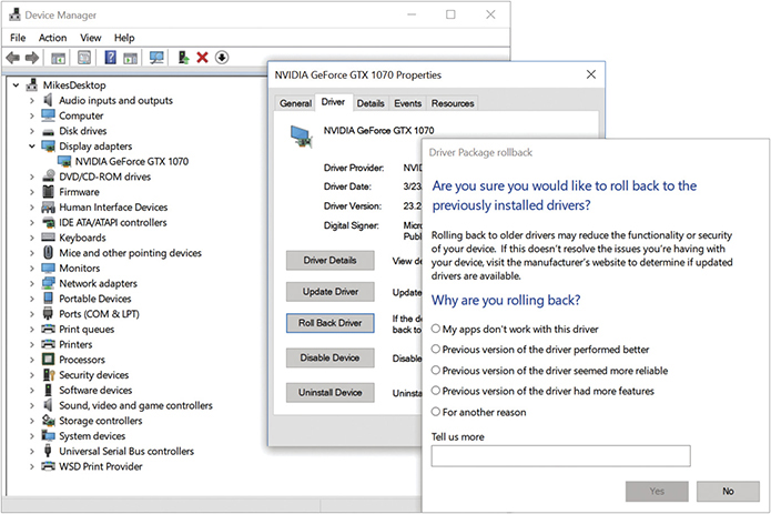
• Figure 6.31 Driver rollback feature
Step 4: Verification
As a last step in the installation process, inspect the results of the installation and verify that the device works properly. Immediately after installing, you should open Device Manager and verify that Windows sees the device (see Figure 6.32). Assuming that Device Manager shows the device working properly, your next check is to put the device to work by making it do whatever it is supposed to do. If you installed a printer, print something; if you installed a scanner, scan something. If it works, you’re finished!
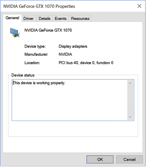
• Figure 6.32 Device Manager shows the device working properly.
Tech Tip
Beta Drivers
Many PC enthusiasts try to squeeze every bit of performance out of their PC components, much as auto enthusiasts tinker with engine tunings to get a little extra horsepower out of their engines. Expansion card manufacturers love enthusiasts, who often act as free testers for their unpolished drivers, known as beta drivers. Beta drivers are fine for the most part, but they can sometimes cause amazing system instability—never a good thing! If you use beta drivers, make sure you know how to uninstall or roll back to previous drivers.
Troubleshooting Expansion Cards
A properly installed expansion card rarely makes trouble; it’s the botched installations that produce headaches. Chances are high that you’ll have to troubleshoot an expansion card installation at some point, usually from an installation you botched personally.
The first sign of an improperly installed card usually shows up the moment you first try to get that card to do whatever it’s supposed to do, and it doesn’t do it. When this happens, your primary troubleshooting process is a reinstallation—after checking in with Device Manager.
Other chapters in this book cover specific hardware troubleshooting. For example, troubleshooting video cards is covered in Chapter 17. Use this section to help you decide what to look for and how to deal with the problem.
Device Manager provides the first diagnostic and troubleshooting tool in Windows. After you install a new device, Device Manager gives you many clues if something has gone wrong.
Occasionally, Device Manager may not even show the new device. If that happens, verify that you inserted the device properly and, if needed, that the device has power. Run the Add Hardware Wizard and see if Windows recognizes the device (see Figure 6.33). In Windows, you run the program by clicking Start and typing the name of the executable in the Search bar: hdwwiz.exe.
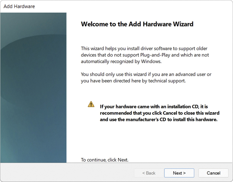
• Figure 6.33 Running Add Hardware Wizard in Windows 11
If Device Manager doesn’t recognize the device at this point, you have one of two problems: either the device is physically damaged and you must replace it, or the device is an onboard device, not a card, and is turned off in CMOS.
Device Manager rarely completely fails to see a device. More commonly, device problems manifest themselves in Device Manager via error icons:
■ A black “!” on a triangle indicates that a device is missing (see Figure 6.34), that Windows does not recognize a device, or that there’s a device driver problem. A device may still work even while producing this error.

• Figure 6.34 An “!” in Device Manager, indicating a problem with the selected device
■ A black downward-pointing arrow on a white field indicates a disabled device. This usually points to a device that’s been manually turned off, or a damaged device. A device producing this error will not work.
The “!” symbol is the most common error symbol and usually the easiest to fix. First, double-check the device’s connections. Second, try reinstalling the driver with the Update Driver button. To get to the Update Driver button, right-click the desired device in Device Manager and select Update driver to open the updating wizard (see Figure 6.35).

• Figure 6.35 Updating the driver
If you get a downward-pointing arrow, first check that the device isn’t disabled. Right-click the device and select Enable. If that doesn’t work (it often does not), try rolling back the driver (if you updated the driver) or uninstalling (if it’s a new install). Shut the system down and make triple-sure you have the card physically installed. Then redo the entire driver installation procedure, making sure you have the most current driver for that device. If none of these procedures works, return the card—it’s almost certainly bad.
■ Upgrading and Installing Motherboards
To most techs, the concept of adding or replacing a motherboard can be extremely intimidating. It really shouldn’t be; motherboard installation is a common and necessary part of PC repair. It is inexpensive and easy, although it can sometimes be a little tedious and messy because of the large number of parts involved. This section covers the process of installation and replacement and shows you some of the tricks that make this necessary process easy to handle.
Choosing the Motherboard and Case
Choosing a motherboard and case can prove quite a challenge for any tech, whether newly minted or a seasoned veteran. You first have to figure out the type of motherboard you want, such as AMD- or Intel-based. Then you need to think about the form factor, which of course influences the type of case you’ll need. Third, how rich in features is the motherboard and how tough is it to configure? You have to read the motherboard manual to find out. Finally, you need to select the case that matches your space needs, budget, and form factor. Now look at each step in a little more detail.
First, determine what motherboard you need. What CPU are you using? Will the motherboard work with that CPU? Because most of us buy the CPU and the motherboard at the same time, make the seller guarantee that the CPU will work with the motherboard. How much RAM do you intend to install? Are extra RAM sockets available for future upgrades?
Try This!
Building a Recommendation
Family, friends, and potential clients often solicit the advice of a tech when they’re thinking about upgrading their PC. This solicitation puts you on the spot to make not just any old recommendation, but one that works with the needs and budget of the potential upgrader. To handle this scenario successfully, you need to manage expectations and ask the right questions, so try this!
What does the upgrader want to do that compels him or her to upgrade? Write it down! Some of the common motivations for upgrading are to play that hot new game or to take advantage of new technology. What’s the minimum system needed to run tomorrow’s action games? What do you need to make multimedia sing? Does the motherboard need to have SuperSpeed USB 3.0 or SuperSpeed USB 10 Gbps (USB 3.2 Gen 2) built in to accommodate digital video or some other special purpose?
How much of the current system does the upgrader want to save? Upgrading a motherboard can very quickly turn into a complete system rebuild. What form factor is the old case? If it’s a microATX case, that constrains the motherboards you can use with it to microATX. If the desired motherboard is a full-sized ATX board, you’ll need to get a new case. Does the new motherboard possess the same type of CPU socket as the old motherboard? If not, that’s a sure sign you’ll need to upgrade the CPU as well.
What about RAM? If the old motherboard was using DDR3 SDRAM, and the new motherboard requires DDR4, you’ll need to replace the RAM. If you need to upgrade the memory, it is best to know how many channels the new RAM interface supports, because performance is best when all channels are populated.
Once you’ve gathered information on motivation and assessed the current PC of the upgrader, it’s time to get down to business: field trip time! This is a great excuse to either physically go to the computer store and check out the latest motherboards and gadgets or simply visit their website. Don’t forget to jot down notes and prices. By the end of your in-person or virtual field trip, you should have the information to give the upgrader an honest assessment of what an upgrade will entail, at least in monetary terms. Be honest—in other words, don’t just tell upgraders what you think they want to hear—and you won’t get in trouble.
A number of excellent motherboard manufacturers currently exist. Some of the more popular brands are ASUS, AsRock, GIGABYTE, and MSI. Your supplier may also have some lesser-known but perfectly acceptable brands of motherboards. As long as the supplier has an easy return policy, it’s fine to try one of these.
Second, make sure you’re getting a form factor that works with your case. Don’t try to put a regular ATX motherboard into a microATX case!
Third, all motherboards come with a technical manual, better known as the motherboard book (see Figure 6.36). You must have this book! This book is your primary source for all of the critical information about the motherboard. If you set up CPU or RAM timings incorrectly in CMOS, for example, and you have a dead PC, where would you find the CMOS-clear jumper? Where do you plug in the speaker? Even if you let someone else install the motherboard, insist on the motherboard book; you will need it.

• Figure 6.36 Motherboard box and book
Tech Tip
Replacement Motherboard Books
If you have a motherboard with no manual, you can usually find a copy of the manual in Adobe Acrobat (.PDF) format online at the manufacturer’s Web site. Make sure you match the revision number of the motherboard as well as the model number.
It’s a good idea to grab and print a copy to keep with the motherboard. I often tape a copy of the manual (either hard copy, burned onto a disc, or copied to a USB drive) in the case where I installed the motherboard. A good spot is in an unused drive bay. Just don’t cover any vents!
Fourth, pick your case carefully. Cases come in many sizes: slimline, desktop, mini-tower, mid-tower, tower, and cube. You can also get specialized cases, such as tiny cases for entertainment systems or ones that fit the same format as a stereo receiver or DVD player. The latter case is called a home theater PC (HTPC), an example of which is shown in Figure 6.37.

• Figure 6.37 An HTPC
Slimline and desktop models generally sit on the desk, beneath the monitor. The various tower cases usually occupy a bit of floor space next to the desk. The mini-tower and mid-tower cases are the most popular choices. Make sure you get a case that fits your motherboard—most microATX cases are too small for a regular ATX motherboard. Cube cases generally require a specific motherboard, so be prepared to buy both pieces at the same time. A quick test-fit before you buy saves a lot of return trips to the supplier.
Better cases offer tool-free component installation, so you don’t have to screw down cards or drives. They just snap into place. You’ll still need a trusty screwdriver to secure the motherboard, though. No installation is completely tool-free yet.
Power supplies sometimes come with the case. Watch out for “really good deal” cases because that invariably points to a cheap or missing power supply. You also need to verify that the power supply has sufficient wattage. This issue is handled in Chapter 7.
Installing the Motherboard
If you’re replacing a motherboard, first remove the old motherboard. Begin by removing all of the cards. Also remove anything else that might impede removal or installation of the motherboard, such as a hard drive. Keep track of your screws—the best idea is to return the screws to their mounting holes temporarily, at least until you can reinstall the parts. Sometimes you even have to remove the power supply temporarily to enable access to the motherboard.
Unscrew the motherboard. It will not simply lift out. The motherboard mounts to the case via small connectors called standoffs that screw into the bottom of the case (see Figure 6.38). Screws then go into the standoffs to hold the motherboard in place. Be sure to place the standoffs properly before installing the new motherboard.

• Figure 6.38 Standoff in a case, ready for the motherboard
![]()
When you insert the new motherboard, do not assume that you will put the screws and standoffs in the same place as they were in your old motherboard. When it comes to the placement of screws and standoffs, only one rule applies: anywhere it fits. Do not be afraid to be a little tough here! Installing motherboards can be a wiggling, twisting, knuckle-scraping process.
![]()
The next part of motherboard installation is connecting the LEDs, buttons, and front-mounted ports on the front of the box. This is sometimes easier to do before you install the motherboard fully in the case. You can trace the wire leads from the front of the case to the appropriate standoffs on the motherboard. These usually include the following:
■ Soft power button
■ Reset button
■ Speaker
■ Hard drive activity light
■ Power light
■ USB
■ Sound
■ Thunderbolt
These wires have specific pin connections to the motherboard. Although you can refer to the motherboard book for their location, usually a quick inspection of the motherboard will suffice for an experienced tech (see Figure 6.39).
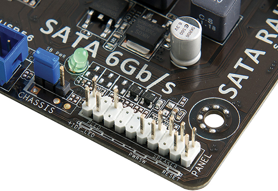
• Figure 6.39 Motherboard wire connections labeled on the motherboard
Tech Tip
Before the Case
A lot of techs install the CPU, CPU fan, and RAM into the motherboard before installing the motherboard into the case. This helps in several ways, especially with a new system. First, you want to make certain that the CPU and RAM work well with the motherboard and with each other—without that, you have no hope of setting up a stable system. Second, installing these components first prevents the phenomenon of flexing the motherboard. Some cases don’t provide quite enough support for the motherboard, and pushing in RAM can make the board bend. Third, attaching a CPU fan can be a bear of a task, one that’s considerably easier to do on a table top than within the confines of a case. A lot of third-party CPU fan and heat-sink assemblies mount on brackets on the bottom of the motherboard, requiring installation before placement in the case.
You need to follow a few rules when installing these wires. First, the lights are LEDs, not light bulbs; they have a positive side and a negative side. If they don’t work one way, turn the connector around and try the other. Second, when in doubt, guess. Incorrect installation only results in the device not working; it won’t damage the computer. Refer to the motherboard book for the correct installation. The third and last rule is that, with the exception of the soft power switch on an ATX system, you do not need any of these wires for the computer to run.
No hard-and-fast rule exists for determining the function of each wire. Often the function of each wire is printed on the connector (see Figure 6.40). If not, track each wire to the LED or switch to determine its function.
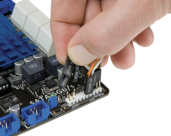
• Figure 6.40 Sample of case wires
Finally, install the motherboard into the case fully and secure it with the appropriate screws. Once you get the motherboard mounted in the case, with the CPU and RAM properly installed, it’s time to insert the power connections and test it. A POST card can be helpful with the system test because you won’t have to add the speaker, a video card, monitor, and keyboard to verify that the system is booting. If you have a POST card, start the system, and watch to see if the POST takes place—you should see a number of POST codes before the POST stops. If you don’t have a POST card, install a keyboard, speaker, video card, and monitor. Boot the system and see if the BIOS information shows up on the screen. If it does, you’re probably okay. If it doesn’t, it’s time to refer to the motherboard book to see where you made a mistake.
If you get no power at all, check to make sure you plugged in all the necessary power connectors. If you get power to fans but get nothing on the screen, you could have several problems. The CPU, RAM, or video card might not be connected to the motherboard properly. The only way to determine the problems is to test. Check the easy connections first (RAM and video) before removing and reseating the CPU. Also, see Chapter 7 for more on power issues.
■ Troubleshooting Motherboards
Motherboards fail. Not often, but motherboards and motherboard components can die from many causes: time, dust, cat hair, or simply slight manufacturing defects made worse by the millions of amps of current sluicing through the motherboard traces. Installing cards, electrostatic discharge, flexing the motherboard one time too many when swapping out RAM or drives—any of these factors can cause a motherboard to fail. The motherboard is a hard-working, often abused component of the PC. Unfortunately for the common tech, troubleshooting a motherboard problem can be difficult and time-consuming. Let’s wrap up this chapter with a look at symptoms of a failing motherboard, techniques for troubleshooting, and the options you have when you discover a motherboard problem.
Symptoms
Motherboard failures commonly fall into three types: catastrophic, component, and ethereal. With a catastrophic failure, the computer just won’t boot. It might have been working just fine; you hear a pop—a loud noise—followed by the acrid smell of ozone, and then you have a dead computer. Use your nose to lead you to a popped capacitor or other motherboard component. Check the power and hard drive activity indicator lights on the front of the PC. Assuming they worked before, having them completely flat points to power supply failure or motherboard failure.
![]()
This sort of problem happens to brand-new systems because of manufacturing defects—often called a burn-in failure—and to any system that gets a shock of ESD. Burn-in failure is uncommon and usually happens in the first 30 days of use. Swap out the motherboard for a replacement and you should be fine. If you accidentally zap your motherboard when inserting a card or moving wires around, be chagrined. Change your daring ways and wear an antistatic wrist strap!
Component failure happens rarely and appears as flaky connections between a device and motherboard or as intermittent problems. A hard drive plugged into a faulty controller on the motherboard, for example, might show up in CMOS autodetect but be inaccessible in Windows. Another example is a USB port that worked fine for months until a big storm took out the external modem hooked to it, and now it doesn’t work, even with a replacement modem.
The most difficult of the three types of symptoms to diagnose are those I call ethereal symptoms. Stuff just doesn’t work all of the time. The PC reboots itself. You get a Blue Screen of Death (BSoD) in the midst of heavy computing, such as right before you smack the villain and rescue the damsel. What can cause such symptoms? If you answered any of the following, you win the prize:
■ Faulty component
■ Buggy device driver
■ Buggy application software
■ Slight corruption of the operating system
■ Power supply problems
Err…you get the picture.
What a nightmare scenario to troubleshoot! The Way of the Tech knows paths through such perils, though, so let’s turn to troubleshooting techniques now.
Techniques
Troubleshooting a potential motherboard failure requires time, patience, and organization. Some problems will certainly be quicker to solve than others. If the hard drive doesn’t work as expected, as in the previous example, check the settings on the drive. Try a different drive. Try the same drive with a different motherboard to verify that it’s a good drive. Like every other troubleshooting technique, what you’re trying to do with motherboard testing is to isolate the problem by eliminating potential causes.
Use a modern POST card with a good diagnostic screen. You’ll find cards that plug into both PCI and PCIe slots, for example, and even USB-based POST cards that enable quick diagnostic tests on portable computers. See Figure 6.41.
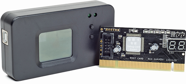
• Figure 6.41 USB POST card (left) and PCI POST card (right)
This three-part system—check, replace, verify good component—works for both simple and more complicated motherboard problems. You can even apply the same technique to ethereal-type problems that might be anything, but you should add one more verb: document. Take notes on the individual components you test so you don’t repeat efforts or waste time. Plus, taking notes can lead to the establishment of patterns. Being able to re-create a system crash by performing certain actions in a specific order can often lead you to the root of the problem. Document your actions. Motherboard testing is time-consuming enough without adding inefficiency.
Options
Once you determine that the motherboard has problems, you have several options for fixing the three types of failures. If you have a catastrophic failure, you must replace the motherboard. Even if it works somewhat, don’t mess around. The motherboard should provide bedrock stability for the system. If it’s even remotely buggy or problematic, get rid of it!
![]()
If you have a component failure, you can often replace the component with an add-on card that will be as good as or better than the failed device. One example of this is a card that can replace the built-in SATA ports on the motherboard (see Figure 6.42).

• Figure 6.42 PCIe SATA card
If your component failure is more a technology issue than physical damage, you can try upgrading the BIOS on the motherboard. As you’ll recall from Chapter 5, every motherboard comes with a small set of code that enables the CPU to communicate properly with the devices built into the motherboard. You can quite readily upgrade this programming by flashing the BIOS: running a small command-line program to write a new BIOS in the flash ROM chip. Refer to Chapter 5 for the details on flashing.
Tech Tip
Limits of BIOS Upgrades
Flashing the BIOS for a motherboard can fix a lot of system stability problems and provide better implementation of built-in technology. What it cannot do for your system is improve the hardware. If AMD comes out with a new, improved, lower-voltage A-Series CPU, for example, and your motherboard cannot scale down the voltage properly, you cannot use that CPU—even if it fits in your motherboard’s Socket AM4. No amount of BIOS flashing can change the hardware built into your motherboard.
Finally, if you have an ethereal, ghost-in-the-machine type of problem that you have finally determined to be motherboard related, you have only a couple of options for fixing the problem. You can flash the BIOS in a desperate attempt to correct whatever it is, which sometimes does work and is less expensive than the other option, which is replacing the motherboard.
Chapter 6 Review
■ Chapter Summary
After reading this chapter and completing the exercises, you should understand the following facts about motherboards.
Explain how motherboards work
■ Every piece of hardware connects either directly or indirectly to the motherboard. Wires called traces make up the buses on the system, enabling hardware to communicate. Motherboards are several layers thick, with traces running across each layer, creating a veritable highway of wires.
■ Motherboards are defined by their form factor, chipset, and components. The form factor defines the physical size and airflow; the chipset defines the type of CPU, the type and amount of RAM, and the components a motherboard will support.
■ The Advanced Technology (AT) form factor, though now obsolete, was the predominant form factor for motherboards through the mid-1990s. Its identifying features included a large keyboard plug.
■ The Advanced Technology Extended (ATX) form factor replaced AT as the form factor of choice by the late 1990s. It offered several improvements over AT, including repositioning the power supply for better airflow, easier access to CPU and RAM slots, and better performance by moving RAM closer to the northbridge and CPU. The microATX (µATX) form factor is a subtype of ATX and is considerably smaller.
■ The ITX form factor is newer than ATX and is designed to support small form factor (SFF) systems. While the regular ITX form factor never gained acceptance, the Mini-ITX form factor is quite popular.
■ Several PC manufacturers make proprietary motherboards, meaning they do not adhere to a standard form factor such as ATX or Mini-ITX. These proprietary motherboards enable these companies to create systems that stand out from the generic ones and, not coincidently, push you to get service and upgrades from their authorized dealers.
■ Motherboards come with differing features or components such as USB ports, audio, networking, video, and RAID. Sometimes a motherboard supports several USB ports but does not have rear ports for all of them. In this case, the motherboard likely has headers for the additional ports to be used in conjunction with a header cable to create front-mounted ports.
Recognize modern expansion buses
■ Every device in the computer connects to the external data bus and the address bus. Expansion slots enable expansion cards to connect to these same buses. In older systems, the expansion slots connect either to the southbridge or to the northbridge. On newer systems, the expansion slots connect to the CPU. Many systems have more than one type of expansion bus, with slots connected to both the chipset and the CPU.
■ Expansion buses run at a standardized speed, depending on the type of expansion bus. This speed, which is much slower than the frontside bus, is dictated by the expansion bus crystal. The chipset uses wait states and buffers to compensate for the difference in speed between the expansion and frontside buses.
■ PCI was 32 bits, ran at 33 MHz, and was self-configuring (no manual configuration of expansion card jumpers). Additionally, it coexisted with other expansion buses.
■ Enhancements to the PCI bus paved the way for a few modern variations, most notably, PCI Express.
■ PCI Express (PCIe), with its point-to-point serial connection, touts speeds as high as 32 GBps. PCIe ×16 slots are commonly used for video cards. Other internal slots you’ll find are ×1 and ×4. A slot can contain fewer lanes than its physical size suggests, and some motherboard don’t have enough lanes for everything to run at full speed. In this case, adding more cards can slow down performance of existing hardware.
■ Installing an expansion card successfully—another one of those bread-and-butter tasks for the PC tech—requires at least four steps. First, you need to know that the card works with your system and your operating system. Second, you have to insert the card in an expansion slot properly and without damaging that card or the motherboard. Third, you need to provide drivers for the operating system—proper drivers for the specific OS. Fourth, you should always verify that the card functions properly before you walk away from the PC.
■ The first sign of an improperly installed expansion card usually shows up the moment you first try to get that card to do whatever it’s supposed to do, and it doesn’t do it. When this happens, your primary troubleshooting process is a reinstallation—after checking in with Device Manager.
Upgrade and install motherboards
■ Not all motherboards fit in all cases. If you upgrade a motherboard, make sure the new motherboard fits in the existing case. If you purchase a new motherboard and a new case, make sure you purchase a case that supports the form factor of your motherboard.
■ Determine the CPU you or your client wants before purchasing a motherboard. Not all CPUs are supported by, or even fit in, all motherboards. Make sure your motherboard supports your CPU, and, if possible, purchase a motherboard that supports higher speeds than your CPU in case you want to upgrade the processor at a later time.
■ To replace a motherboard, first remove all of the expansion cards from the old motherboard. Unscrew the motherboard and remove it from the case.
■ Before installing a new motherboard in the case, attach the CPU, heat sink/fan, and RAM. Check the standoffs in the case—you might have to add or remove a few to accommodate the new motherboard. Once installed, boot the system and make sure there are no POST errors and the BIOS information appears on the screen. Then install any expansion cards.
■ Cases come with a series of little wires that connect to LEDs on the front of the case. You need to plug these wires in to the motherboard for the LEDs to function. LEDs have a positive side and a negative side, so the wires must be connected the right way or the LEDs will not work. If you find that the LEDs are not working, turn the connector around to reverse the positive/negative connection. Getting it wrong will not damage your system; it will only cause the LEDs not to light up.
Troubleshoot motherboard problems
■ Motherboards and motherboard components can die for many reasons, including time, dust, pet hair, manufacturing defects, ESD, or physical damage. Motherboard failures usually fall into one of three main categories: catastrophic, component, or ethereal.
■ Catastrophic failure is typically caused by manufacturing defects (burn-in failure) or ESD. Burn-in failures are uncommon and usually manifest within the first 30 days of use. In the case of a catastrophic failure, replace the motherboard.
■ Component failure appears as a flaky connection between a device and the motherboard or as intermittent problems. In the case of a component failure, replace the failed component with an expansion card or peripheral device. Sometimes a BIOS upgrade can fix component failures.
■ Ethereal failure is the most difficult to diagnose. Symptoms vary from the PC rebooting itself to Blue Screens of Death and can be caused by a faulty component, buggy device driver, buggy application software, operating system corruption, or power supply problems.
■ Use three steps to troubleshoot problems: check, replace, and verify. For example, first check the settings of the problem device. If the device still fails, replace the device. If the device continues to malfunction, try the device with a different motherboard. Remember to document your troubleshooting steps. Not only will it help you to become an efficient troubleshooter, but it also can lead to the establishment of patterns. Being able to re-create a system crash by performing certain actions in a specific order can often lead you to the root of the problem.
■ Key Terms
ATX
burn-in failure
catastrophic failure
chipset
component failure
device driver
expansion bus
expansion bus crystal
expansion slot
form factor
headers
ITX
microATX
Mini-ITX
motherboard
motherboard book
PCI Express (PCIe)
Peripheral Component Interconnect (PCI)
printed circuit board (PCB)
riser card
standoffs
Super I/O chip
traces
transfer rate
unsigned driver
Windows Hardware Compatibility Program
■ Key Term Quiz
Use the Key Terms list to complete the sentences that follow. Not all terms will be used.
1. The __________________ defines the type of processor and RAM required for the motherboard and determines to a degree the built-in devices supported by a motherboard, including the expansion slots.
2. The __________________ determines the physical size of the motherboard as well as the general location of components and ports.
3. The smallest common ATX motherboard form factor is the __________________.
4. The most common small non-ATX motherboard form factor is the __________________.
5. The most popular expansion bus in use today, with speeds up to 32 GBps, is __________________.
6. The __________________ is your primary source for all of the critical information about the motherboard.
7. The motherboard mounts to the case via small connectors called __________________ that screw into the bottom of the case.
8. You can add features to a system by adding a device to a(n) __________________.
9. Every piece of hardware, from the CPU to an expansion card, directly or indirectly, plugs into the motherboard and contains wires called __________________ that make up the buses of the system.
10. Microsoft truly wants your computer to work, so they provide an excellent and rigorous testing program for hardware manufacturers called the __________________.
■ Multiple-Choice Quiz
1. Which of the following is part of the ATX form factor?
A. Mini-ITX
B. macroATX
C. microATX
D. picoATX
2. Which of the following form factors dominates the PC market?
A. AT
B. ATX
C. Mini-ITX
D. Pico-ITX
3. Which of the following slots features serial data transfers?
A. AGP
B. PCI
C. PCIe
D. PCI-X
4. A client brought in an old computer that won’t boot. He wants to see if any data can be recovered from the hard drive. When the tech opened the case, she noted that two expansion cards were plugged into some kind of circuit board that plugged into the motherboard. The expansion cards were parallel with the motherboard, in other words, rather than perpendicular. Into what kind of circuit board did the expansion cards most likely connect? (Select two.)
A. Daughter board
B. Expansion board
C. Riser card
D. Southbridge
5. Julie installed a new TV tuner card in a client’s computer. The card fit perfectly in a PCIe ×1 slot and clipped down to the case properly. What’s her next step?
A. Research the card
B. Install drivers
C. Verify functionality
D. Troubleshoot
6. In a routine check of a system newly built by her latest intern, Sarah discovers that everything works except the hard drive and power LEDs on the front of the case. What could be the problem? (Select two.)
A. The intern forgot to connect the LED leads to the motherboard.
B. The intern reversed the LED leads to the motherboard.
C. There is no power to the motherboard.
D. There is no activity on the hard drive.
7. Robert installed a new motherboard, CPU, and RAM into his old case. After he attached the power correctly and pressed the power button, not only did the system not boot up, but he smelled ozone and realized the motherboard had shorted out. What could have been the cause?
A. Robert installed an ATX motherboard into an ITX case.
B. Robert installed an ITX motherboard into an ATX case.
C. Robert used an ITX power supply on an ATX motherboard.
D. Robert left a standoff in the wrong place under the motherboard.
8. Which of the following enables you to access the Add Hardware Wizard in Windows?
A. addhdware.exe
B. hdware.exe
C. hdwwiz.exe
D. addhwiz.exe
9. Brian bought a new motherboard that advertised support for eight USB ports. When he pulled the motherboard out of the box, though, he found that it only had four USB ports. What’s likely the issue here?
A. The extra four USB ports will connect to the front of the case or via a header cable to an expansion slot.
B. The extra four USB ports require an add-on expansion card.
C. Each USB port will have a splitter that makes it two USB ports.
D. The motherboard chipset might support eight USB ports, but the manufacturer only included four ports.
10. Martin bought a new motherboard to replace his older ATX motherboard. As he left the shop, the tech on duty called after him, “Check your standoffs!” What could the tech have meant?
A. Standoffs are the connectors on the motherboard for the front panel buttons, such as the on/off switch and reset button.
B. Standoffs are the metal edges on some cases that aren’t rolled.
C. Standoffs are the metal connectors that attach the motherboard to the case.
D. Standoffs are the header cables that enable a motherboard to support more than four USB ports.
11. Amanda bought a new system that, right in the middle of an important presentation, gave her a Blue Screen of Death. Now her system won’t boot at all, not even to CMOS. After extensive troubleshooting, she determined that the motherboard was at fault and replaced it. Now the system runs fine. What was the most likely cause of the problem?
A. Burn-in failure
B. Electrostatic discharge
C. Component failure
D. Power supply failure
12. Solon has a very buggy computer that keeps locking up at odd moments and rebooting spontaneously. He suspects the motherboard. How should he test it?
A. Check settings and verify good components.
B. Verify good components and document all testing.
C. Replace the motherboard first to see if the problems disappear.
D. Check settings, verify good components, replace components, and document all testing.
13. Which of the following companies makes chipsets?
A. AMI
B. GIGABYTE
C. MSI
D. AMD
14. What purpose does the Super I/O chip serve?
A. The Super I/O chip handles the communication with RAM.
B. The Super I/O chip handles the communication with video.
C. The Super I/O chip handles the communication with legacy devices.
D. The Super I/O chip handles the communication between the northbridge and southbridge chips.
15. What should you do before installing an expansion card? (Select two.)
A. Attach an antistatic wrist strap.
B. Install the drivers.
C. Plug the PC into a grounded outlet.
D. Unplug the PC.
■ Essay Quiz
1. This chapter talks about motherboards made in layers that contain the wires or traces. Find an Internet site that talks about the motherboard manufacturing process. Why do you think motherboards are made in layers? What advantages do the layers provide?
2. Some people believe that selecting a motherboard based on the motherboard chipset is even more important than basing the decision on the kind of processor. Do you agree or disagree, and why?
3. Prepare a PowerPoint presentation or write a paper that would help your classmates select and replace a bad motherboard. Be sure to walk through all of the necessary steps.
4. Your neighbors Dora and Jim just learned that you’re studying computer hardware. They feel that their computer is slightly out of date. They want to upgrade the processor, but not the motherboard. Prepare a list of at least five questions you should ask them before you know what CPU they can choose or whether it is feasible to upgrade their system.
Lab Projects
• Lab Project 6.1
Examine all of the ports and connectors on the back of your computer. With the computer turned off, you may disconnect the cables from the ports. (If necessary, document where and how the cables are connected so you can replace them correctly.) Determine the kinds of ports that are built in and those that are provided by expansion cards. From this information alone, can you ascertain whether your motherboard is an ATX or ITX form factor? What else would you need to know, if anything? Draw a diagram of the back of your system and label every port and all connectors. State if their sources are from the motherboard or from an expansion card. Last, state the form factor of the motherboard.
• Lab Project 6.2
One of the most important skills a PC technician can possess is the ability to read and interpret documentation. No single piece of documentation is as important as the motherboard book. See how well you can understand this documentation. Consult your motherboard book or use one that your instructor provides. (If you do not have the motherboard book, try to download it from the manufacturer’s Web site.) Then write a paragraph about your motherboard that includes answers to the following questions:
■ What make and model is the motherboard?
■ What chipset does it use?
■ What kinds of RAM slots does it contain?
■ What kinds of expansion slots does it have and how many of each kind does it have?
■ What kinds of onboard ports does it have?
■ What kinds of CPUs does it support and what kind of processor slot does it have?
■ Does it use jumpers or dip switches for configuration? If so, what do the jumpers or dip switches control?
■ What form factor does it use? (Hint: Consult the motherboard book to see if it contains an illustration of the way the motherboard components are laid out.)
■ What unusual or proprietary features does it have?
• Lab Project 6.3
You know now how important the motherboard chipset is in determining the kind of CPU and RAM that you can install in the computer. You also know that motherboards may look similar but have very different features and prices. Imagine that you are going to build a new computer by ordering the components. Price is not a problem, so you will want to select the best and most powerful components. On the Internet, search sites such as https://www.intel.com or https://www.amd.com along with sites such as https://www.newegg.com to select a motherboard and a particular chipset. Then select a compatible CPU and RAM. Explain where you found the information about the components, what brands/models you selected, and how much each will cost.
Now imagine that your budget will not allow you to buy these components at this time. In fact, you’ve decided that you can afford only 75 percent of the cost of these components. What will you do to save money? Will you change the motherboard and the chipset or will you use a less powerful CPU with a smaller amount of RAM? Consider what you can upgrade at a later time when you have more available cash. Search the Internet again and select components that would be satisfactory but are not the latest and the greatest. Be sure that the CPU and RAM you select are indeed compatible with your motherboard and chipset. What did you select and how much will it cost you?
• Lab Project 6.4
Open your computer case and determine the kind of expansion slots available on your motherboard. How many of each kind are available? What cards are installed in the slots? Now examine the back and front of the computer case to see what ports are available. What devices do you have plugged into the ports?