chapter 19
Local Area Networking
“Networking, I’m user friendly Networking, I install with ease Data processed, truly Basic I will upload you, you can download me”
—“NETWORKING,” WARREN ZEVON

In this chapter, you will learn how to
■ Explain the basics of interconnecting networks with TCP/IP
■ Install and configure wired networks
■ Understand network organization and access controls
■ Troubleshoot wired networks
Networks dominate the modern computing environment. A vast percentage of businesses have PCs connected in a small local network, and big businesses simply can’t survive without connecting their many offices into a single large network.
Because networks are so common today, every good tech needs to know the basics of networking technology, operating systems, implementation, and troubleshooting. Accordingly, this chapter teaches you how to build and troubleshoot a basic network.
The first part of this chapter explores the TCP/IP protocol suite and how Windows uses it in a typical network. Every modern network uses TCP/IP for communicating among devices. You need to know this stuff.
Next, we’ll go through the process of setting up a small network from start to finish. This includes details on planning a network, installing and configuring network interface cards (NICs), setting up switches, and configuring TCP/IP.
From there, we’ll turn to how we organize modern networks—and control access to all of the resources connected to them.
The chapter closes with troubleshooting a network. Modern operating systems come with plenty of tools to help you when the network stops functioning. I’ll show you the tools and combine that with a troubleshooting process that helps you get a network up and running again.
1101/1102
■ Interconnecting Networks
Ethernet hardware protocol does a fine job of moving data directly from one machine to another inside our network, as you learned in Chapter 18. Up to this point, the only way to distinguish one machine from another is by the MAC address on its network interface card (NIC). But sending a message to any of the billions of networked devices in our world that aren’t inside our network is a little more complicated. How, for example, would you address a device that doesn’t even use Ethernet? (They exist!) How would you send a message to a laptop without knowing whether it’s in Alaska or Antarctica?
These questions (and many others) about how to pass messages between networks are answered by another layer of software called the network protocol. Over the years there have been many network protocols, most combining multiple simple protocols into groups called protocol stacks or protocol suites, but Transmission Control Protocol/Internet Protocol (TCP/IP) is the primary protocol of most modern networks, including the Internet.
In contrast to physical MAC addresses directly tied to the hardware, IP introduces its own logical addressing scheme that isn’t coupled to the hardware. IP addressing is hierarchical—devices higher up in each hierarchy know how to direct traffic to addresses within that hierarchy. Each device doesn’t need to know exactly how to send a message to every other device—it just needs to know how to send it one step closer to the top of the hierarchy the recipient is under.
Just as switches (which filter and forward by MAC address) interconnect systems on a LAN, we can interconnect LANs themselves into larger wide area networks (WANs) with routers—devices that filter and forward by IP address. A single WAN (see Figure 19.1) might be under the control of a single organization—or it might interconnect multiple organizations, as the Internet does.

• Figure 19.1 WAN concept
Every LAN that connects to the Internet must have a router to interconnect it with an Internet service provider (ISP). A typical SOHO router, like the one shown in Figure 19.2, will have two connections to enable it to connect to two different LANs, but large enterprise routers (like the ones at an ISP) may interconnect dozens of LANs.

• Figure 19.2 Typical SOHO router
One port on the router connects to your LAN’s switch and receives an IP address that’s part of your network. The other port on the router connects to the next network, usually to your ISP, which in turn connects to millions of other routers and billions of other computers (see Figure 19.3). The IP address of the “LAN” side of your router (the port connected to your LAN) is the address your computer uses to send data to anything outside your network. This is called the default gateway.

• Figure 19.3 Default gateway
In this section, we’ll investigate a number of topics related to interconnecting networks, including the two IP network-addressing schemes (IPv4 and IPv6), the role DNS plays, the two main transmission protocols in the TCP/IP suite, and the settings and tools you should understand to actually work with TCP/IP.
Network Addressing with IPv4
Any network address must provide two pieces of information: it must uniquely identify the machine and it must locate that machine within the larger network. In a TCP/IP network, the IP address identifies the node and the network on which it resides. If you look at an IP address, it’s not apparent which part of the address identifies the network and which part is the unique identifier of the computer.
IP Addresses
The IP address is the unique identification number for your system on the network. Many systems today still rely on the Internet Protocol version 4 (IPv4) addressing scheme. IPv4 addresses consist of four sets of eight binary numbers (octets), each set separated by a period. This is called dotted-decimal notation. So, instead of a computer being called SERVER1, it gets an address like so:
202.34.16.11
Written in binary form, the address would look like this:
11001010.00100010.00010000.00001011
To make the addresses more comprehensible to users, the TCP/IP folks decided to write the decimal equivalents:
00000000 = 0
00000001 = 1
00000010 = 2
. . .
11111111 = 255
Subnet Mask
Part of every IP address identifies the network (the network ID), and another part identifies the local computer (the host ID, or host) on the network. A NIC uses a value called the subnet mask to distinguish which part of the IP address identifies the network ID and which part of the address identifies the host. The subnet mask blocks out (or masks) the network portion of an IP address.
Let’s look at a typical subnet mask: 255.255.255.0. When you compare the subnet mask to the IP address, any part that’s all 255s is the network ID. Any part that’s all zeros is the host ID. Look at the following example:
IP address: 192.168.4.33
Subnet mask: 255.255.255.0
Because the first three octets are 255, the network ID is 192.168.4 and the host ID is 33.
Every computer on a single LAN must have the same network ID and a unique host ID. That means every computer on the preceding network must have an IP address that starts with 192.168.4. Every computer on the network must have a unique IP address. If two computers have the same IP address, they won’t be able to talk to each other, and other computers won’t know where to send data. This is called an IP conflict.
You can never have an IP address that ends with a 0 or a 255, so for the preceding example, the LAN can have addresses starting at 192.168.4.1 and ending at 192.168.4.254: a total of 254 addresses.
Originally, subnets fell into “classes,” such as A, B, or C, determined by the corresponding octet in the subnet mask. A Class C address, like the one just discussed, had a subnet mask of 255.255.255.0. A Class B address, in contrast, had a subnet mask of 255.255.0.0. The latter class left two full octets (16 bits) just for host numbers. That meant a single Class B network ID could have 216 – 2 unique host IDs = 65,534 addresses. For completeness, note that a Class A address subnet mask was 255.0.0.0.

Although it’s still common to see subnet masks as one to three groups of “255,” the class system is long gone. Because the subnet mask numbers are binary, you can make a subnet with any number of ones in the subnet mask.
The current system is called Classless Inter-Domain Routing (CIDR) and it works easily in binary, but a little less prettily when you show the numbers in the octets. A quick example should suffice to illustrate this point.
A subnet mask of 255.255.255.0 translates into binary as such:
11111111.11111111.11111111.00000000
With CIDR, network techs refer to the subnet mask by the number of ones it contains. The preceding subnet mask, for example, has 24 ones. Jill the tech would call this subnet a /24 (whack twenty-four). As you’ve seen already, a /24 network ID offers up to 254 host IDs.
If you want a network ID that enables more host IDs, buy one that has a subnet mask with fewer ones, like this one:
11111111.11111111.11110000.00000000
Count the ones. (There are 20.) The ones mask the network ID. That leaves 12 digits for the host IDs. Do the binary math: 212 – 2 = 4094 unique addresses in a single /20 network ID.
When you change the binary number—11110000—to an octet, you get the following:
255.255.240.0
It might look a little odd to a new tech, but that’s a perfectly acceptable subnet mask. The binary behind the octets works.
From a practical standpoint, all you must know as a tech is how to set up a computer to accept an IP address and subnet mask combination that your network administrator tells you to use.
Network Addressing with IPv6
When the early developers of the Internet set out to create an addressing or naming scheme for devices on the Internet, they faced several issues. Of course, they needed to determine how the numbers or names worked, and for that they developed the Internet Protocol and IP addresses. But beyond that, they had to determine how many computers might exist in the future, and then make the IP address space even bigger to give Internet naming longevity. But how many computers would exist in the future?
The 32-bit IPv4 standard offers only 4 billion addresses. That was plenty in the beginning, but seemed insufficient once the Internet went global.
The Internet Engineering Task Force (IETF) developed an IP addressing scheme called Internet Protocol version 6 (IPv6) that is slowly replacing IPv4. IPv6 extends the 32-bit IP address space to 128 bits, allowing up to 2128 addresses—that should hold us for the foreseeable future!

Although they achieve the same function—enabling computers on IP networks to send packets to each other—IPv6 and IPv4 differ a lot when it comes to implementation. This section provides you with a quick overview to get you up to speed with IPv6 and show you how it differs from IPv4.
IPv6 Address Notation
The notation for a familiar 32-bit IPv4 address—such as 197.169.94.82—contains four octets separated by a period. The 128-bit IPv6 addresses are written like this:
2001:0000:0000:3210:0800:200c:00cf:1234
IPv6 uses a colon as a separator, instead of the period used in IPv4’s dotted-decimal format. Each group is a hexadecimal number between 0000 and ffff called, unofficially, a field or hextet.
A complete IPv6 address always has eight groups of four hexadecimal characters. If this sounds like you’re going to type in really long IP addresses, don’t worry, IPv6 offers a number of ways to shorten the address in written form.
 Tech Tip
Hex
For those who don’t play with hex regularly, one hexadecimal character (for example, F/f) represents 4 bits, so four hexadecimal characters make a 16-bit group. For some reason, the IPv6 developers didn’t provide a name for the “group of four hexadecimal characters,” so many techs and writers have taken to calling them fields or “hextets” to distinguish them from IPv4 “octets.”
First, leading zeros can be dropped from any group, so 00cf becomes cf and 0000 becomes 0. Let’s rewrite the previous IPv6 address using this shortening method:
2001:0:0:3210:800:200c:cf:1234
Second, you can remove one or more consecutive groups of all zeros, leaving the two colons together. For example, using the :: rule, you can write the previous IPv6 address as
2001::3210:800:200c:cf:1234
You can remove any number of consecutive groups of zeros to leave a double colon, but you can only use this trick once in an IPv6 address.
Take a look at this IPv6 address:
fe80:0000:0000:0000:00cf:0000:ba98:1234
Using the double-colon rule, you can reduce four groups of zeros; three of them follow the fe80 and the fourth comes after 00cf. Because of the “only use once” stipulation, the best and shortest option is to convert the address to this:
fe80::cf:0:ba98:1234
You may not use a second :: to represent the fourth groups of zeros—only one :: is allowed per address! This rule exists for a good reason. If more than one :: was used, how could you tell how many groups of zeros were in each group? Answer: you couldn’t.
Here’s an example of a very special IPv6 address that takes full advantage of the double-colon rule, the IPv6 loopback address:
::1
Without using the double-colon nomenclature, this IPv6 address would look like this:
0000:0000:0000:0000:0000:0000:0000:0001
IPv6 uses the “/x” prefix length naming convention, similar to the CIDR naming convention in IPv4. Here’s how to write an IP address and prefix length for a typical IPv6 host:
fe80::cf:0:ba98:1234/64
Where Do IPv6 Addresses Come From?
With IPv4, IP addresses come from one of two places: either you type in the IP address yourself (static IP addressing) or you use DHCP (also called dynamic IP addressing). With IPv6, addressing works very differently. Instead of one IP address, you will have multiple IPv6 addresses on a single network card.
![]()
When a computer running IPv6 first boots up, it gives itself a link-local address, IPv6’s equivalent to IPv4’s APIPA/zeroconf address (we’ll explore APIPA/zeroconf later in this chapter). Although an APIPA/zeroconf address can indicate a loss of network connectivity or a problem with the DHCP server, computers running IPv6 always have a link-local address. The first 64 bits of a link-local address are always fe80::, which means every address always begins with fe80:0000:0000:0000. If your operating system supports IPv6 and IPv6 is enabled, you can see this address. Figure 19.4 shows the link-local address for a typical system running the ipconfig utility.
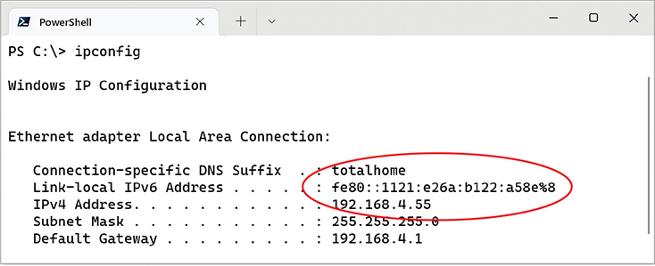
• Figure 19.4 Link-local address in ipconfig
The second 64 bits of a link-local address, the interface ID, are generated in two ways. Every current operating system generates a 64-bit random number. Very old operating systems, such as Windows XP and Windows Server 2003, used the device’s MAC address to create a 64-bit number called an Extended Unique Identifier, 64-bit (EUI-64).
The link-local address does all the hard work in IPv6, and, as long as you don’t need an Internet connection, it’s all you need. The old concepts of static and DHCP addressing don’t really make much sense in IPv6 unless you have dedicated servers (even in IPv6, servers generally still have static IP addresses). Link-local addressing takes care of all your local network needs.
IPv6 Prefix Lengths
Systems use IPv6 prefix lengths to determine whether to send packets to a local MAC address or to the default gateway to send the packets out to the Internet. But you need to focus on two rules:
■ The last 64 bits of an IPv6 address are generated by the NIC, leaving a maximum of 64 bits for the prefix. Therefore, no prefix is ever longer than /64.
■ The five Regional Internet Registries (RIRs) pass out /48 prefixes to big ISPs and end users who need large allotments. ISPs and others will borrow another 16 bits for subnetting and then pass out /64 interface IDs to end users. Link-local addressing uses a prefix length of /64. Other types of IPv6 addresses get the subnet information automatically from their routers.
Global Unicast Addresses
To get on the Internet, a system needs a second IPv6 address called a global unicast address, often referred to as a “global address.” The most common way to get a global address is to request it from the default gateway router, which must be configured to pass out global IPv6 addresses. When you plug a computer into a network, it sends out a very special packet called a router solicitation (RS) message, looking for a router (see Figure 19.5). The router hears this message and responds with a router advertisement (RA). This RA tells the computer its network ID and subnet (together called the prefix) and DNS server (if configured—more on DNS in a moment).
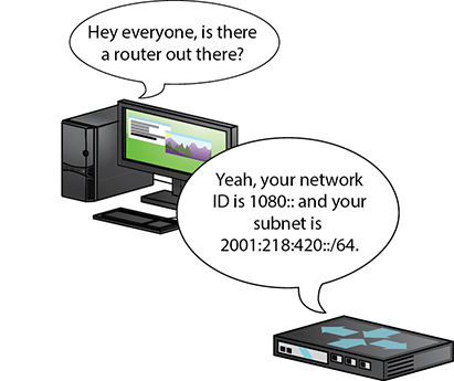
• Figure 19.5 Getting a global unicast address
Once the computer gets a prefix, it generates the rest of the address just like with the link-local address. The computer ends up with a legitimate, 128-bit public IPv6 address as well as a link-local address. Figure 19.6 shows the IPv6 information in macOS.

• Figure 19.6 macOS system with a global IPv6 address
A global address is a true Internet address. If another computer is running IPv6 and also has a global address, it can access your system unless you have some form of firewall.
The addition of IPv6 makes programs such as ipconfig complex. Figure 19.7 shows ipconfig information from a Windows 10 computer.

• Figure 19.7 The ipconfig command with IPv6 and IPv4
Domain Name System
Knowing that users could not remember lots of IP addresses, early Internet pioneers came up with a way to correlate those numbers with more human-friendly designations. The system they came up with is called the Domain Name System (DNS). Special computers, called DNS servers, keep databases that associate IP addresses with names (and store other related information—more on this in a moment).
For example, let’s say a machine with the IP address 34.200.194.131 hosts a Web site and we want it to be known as www.totalsem.com. When we set up the Web site, we would pay for a DNS server to register the DNS name www.totalsem.com to the IP address 34.200.194.131. So instead of typing “https://34.200.194.131” to access the Web page, you could type “www.totalsem.com” and press ENTER. Your system would then query the DNS server to get www.totalsem.com’s IP address and use that to find the right machine. Unless you want to type in IP addresses all the time, you’ll need to use DNS servers (see Figure 19.8).

• Figure 19.8 Domain name system
The Internet regulates domain names. If you want a domain name that others may access on the Internet, you must register your domain name and pay a small yearly fee. Originally, DNS names all ended with one of the following seven domain name qualifiers, called top-level domains (TLDs):

As more and more countries joined the Internet, a new level of domains was added to the original seven to indicate a DNS name from a country, such as .uk for the United Kingdom. It’s common to see DNS names such as www.bbc.co.uk or www.louvre.fr. The Internet Corporation for Assigned Names and Numbers (ICANN) has added tons more generic domains such as .name, .app, and .blog.
A lot of the power of DNS comes from the fact that the database stores a little bit more than just an IP address and the associated name. DNS has several different types of records, and it can store more than one of each for a given name. The CompTIA A+ 1101 objectives only want you to know about address records (A and AAAA) and two types that play a big role in e-mail: MX and TXT records.
Address Records
Address records are how the DNS database keeps track of the names of individual systems on a network. Each individual A record associates one name with an IPv4 address, and each AAAA record associates one name with an IPv6 address. If you need to associate a human-friendly name like “accounting” with the accounting department’s file server, you’ll create an A or AAAA record.
MX Records
MX records enable the servers that handle outgoing e-mail to figure out where e-mail for each domain should go. I let Microsoft 365 handle my e-mail, so the MX record for totalsem.com points to the domain that Microsoft 365 uses for incoming mail. If you shoot me an e-mail at [email protected], your outgoing mail server will look up the MX record and know to send the mail on to Microsoft’s server.
TXT Records Text (TXT) records are basically the junk drawer of the DNS database. People use these free-form records to hold all kinds of things—but the CompTIA A+ 1101 objectives only want you to know about the role they play in spam management. For decades now, the administrators of e-mail servers have been waging an ongoing battle with unscrupulous marketers and scammers who send mountains of unwanted e-mail—spam—24 hours a day.
To that end, TXT records are used for three anti-spam purposes:
■ DomainKeys Identified Mail (DKIM) records Enable receiving servers to verify that the messages they receive were signed by the sending server and have not been altered by intermediate servers.
■ Sender Policy Framework (SPF) records List the IP or DNS addresses allowed to send e-mail for a domain, enabling receiving servers to discard or flag messages sent by illegitimate servers.
■ Domain-based Message Authentication, Reporting, and Conformance (DMARC) records Enable domain owners to indicate what receiving servers should do with e-mail that fails the DKIM or SPF checks. They also enable domain owners to receive reports from large e-mail providers about the origin of the mail they received from the domain.
Entering Client IP Information
When you’re configuring a computer to connect to a network, the operating system must provide you an interface to enter the IP address, the subnet mask, the default gateway, and at least one DNS server. Let’s review:
■ IP address Your computer’s unique address on the network
■ Subnet mask Identifies your network ID
■ Default gateway IP address on the LAN side of your router
■ DNS server Tracks easy-to-remember DNS names for IP addresses
There are two ways to enter IP information on the operating system: statically or dynamically. Figure 19.9 shows the IP settings dialog box. Here you can enter the information statically.

• Figure 19.9 IP settings on a Windows 10 system
As you look at Figure 19.9, note the radio button for Obtain an IP address automatically. This is a common setting for which you don’t need to enter any information. You can use this setting if your network uses Dynamic Host Control Protocol (DHCP). If you have DHCP (most networks do) and your computer is configured to obtain an IP address automatically, your computer boots up and will broadcast a DHCP request.
A DHCP server manages a range of IP addresses (also called its pool or scope). It provides your computer with an address from this pool in the form of a lease containing all the IP information it needs to get on the network (see Figure 19.10) along with the expiration time (after which the computer will need to ask the DHCP server to renew the lease).

• Figure 19.10 A DHCP server handing out an IP address
As previously mentioned (and shown in Figure 19.9), you can also manually input an IP address, creating a static IP address. Static means it doesn’t change until you or some other tech changes it manually. You can also set up the DHCP server to always give a specific IP address to a certain device, such as a server or printer, based on its MAC address. This is called a DHCP reservation. Typically, servers have a reserved IP address if they have not been manually configured.
TCP vs. UDP
When moving data from one system to another, the TCP/IP protocol suite needs to know if the communication is connection-oriented or connectionless. When you want to be positive that the data moving between two systems gets there in good order, use a connection-oriented application. If it’s not a big deal for data to miss a bit or two, then connectionless is the way to go. The connection-oriented protocol used with TCP/IP is called the Transmission Control Protocol (TCP). The connectionless one is called the User Datagram Protocol (UDP). Let me be clear: you don’t choose TCP or UDP. The people who developed the applications decide which protocol to use.
Most TCP/IP applications use TCP. TCP gets an application’s data from one machine to another reliably and completely without the application developer having to think about how to deal with missing packets. As a result, TCP comes with communication rules that require both the sending and receiving machines to acknowledge the other’s presence and readiness to send and receive data.
UDP is the “fire and forget” missile of the TCP/IP protocol suite. UDP doesn’t possess any of the extras you see in TCP to make sure the data is received intact. UDP works best when you have a lot of data to send that doesn’t need to be perfect or when the application has other ways to deal with any missing packets. A few dropped packets on a Voice over IP (VoIP) call, for example, won’t make much difference in the communication between two people. So there’s a good reason to use UDP: it’s smoking fast compared to TCP.
TCP/IP Settings
TCP/IP has a number of unique settings that you must configure correctly to ensure proper network functionality. Unfortunately, these settings can be quite confusing, and there are several of them. Not all settings are used for every type of TCP/IP network, and it’s not always obvious where you go to set them.
In Windows 10, you can configure network settings from the Settings app or appropriate Control Panel applet. Go to Start | Settings | Network & Internet | Status. Click Change adapter options under the Advanced network settings field on the right to get to installed NICs. The Windows 11 Settings app moves things around a little, but from Network & Internet click Advanced network settings and then select the NIC you want to configure.
The CompTIA A+ certification exams assume that someone else, such as a tech support person or some network guru, will tell you the correct TCP/IP settings for the network. You need to understand roughly what those settings do and to know where to enter them so the system works.
TCP/IP Tools
All modern operating systems come with handy tools to test and configure TCP/IP. Those you’re most likely to use in the field are ping, ipconfig, ifconfig, ip, nslookup, dig, tracert, and traceroute. All of these programs are command-line utilities. Open a command prompt to run them.
ping
The ping command provides a really great way to see if you can talk to another system. Here’s how it works. Get to a command prompt or terminal and run ping followed by an IP address or by a DNS name, such as ping google.com. Press the ENTER key and away it goes! Figure 19.11 shows the common syntax for ping.

• Figure 19.11 The ping command’s syntax on Windows
The ping command has a few useful options beyond the basics. The first option to try in Windows is the -t switch. If you use the -t switch, ping continuously sends ping packets until you stop it with the break command (CTRL-C). That’s the default behavior for ping in macOS and Linux; you press CTRL-C again to make it stop. The second option in Windows is the -l switch, which enables you to specify how big a ping packet to send. This helps in diagnosing specific problems with the routers between your computer and the computer you ping.
ipconfig/ifconfig/ip
Windows offers the command-line tool ipconfig for a quick glance at your network settings. From a command prompt, run ipconfig/ all to see all of your TCP/IP settings (see Figure 19.12). The ifconfig command in macOS and other Unixes provides the same level of detail with no switches applied. Much of the Linux world has moved on to the Linux-specific ip command, which is stuffed to the gills with cool features. You can run ip address to get the equivalent information.

• Figure 19.12 An ipconfig /all command in Windows 10
When you have a static IP address, ipconfig does little beyond reporting your current IP settings, including your IP address, subnet mask, default gateway, DNS servers, and WINS servers. When using DHCP, however, ipconfig is also the primary tool for releasing and renewing your IP address. Just run ipconfig /renew to get a new IP address or ipconfig /release to give up the IP address you currently have.
nslookup/dig
The nslookup command is a powerful command-line program that enables you to determine exactly what information the DNS server is giving you about a specific host name. Every modern OS makes nslookup available when you install TCP/IP, though on Unixes I recommend the dig command, which provides more verbose—and more technical—output by default. Figure 19.13 compares what you’ll see if you run nslookup totalsem.com and dig totalsem.com.

• Figure 19.13 Running nslookup and dig in macOS
tracert/traceroute
The tracert (Windows) and traceroute (macOS, Linux) utilities show the route that a packet takes to get to its destination. From a command line, type tracert or traceroute followed by a space and an IP address or URL. The output describes the route from your machine to the destination machine, including all devices the packet passes through and how long each hop between devices takes (see Figure 19.14).

• Figure 19.14 The tracert command in action
These commands can help troubleshoot bottlenecks. You can run them to see if a TCP/IP problem is on a machine or connection you control or if you need to contact another network’s administrators. The path can differ each time when the destination or networks along the way use a load balancer to spread traffic out over several routes or servers. You might even notice that an intermittent problem only rears its head when packets take a specific route or reach a particular destination server!
 Try This!
Running tracert/traceroute
Ever wonder why your e-mail takes years to get to some people but arrives instantly for others? Or why some Web sites are slower to load than others? Part of the blame could lie with how many hops away your connection is from the target server. You can use tracert/traceroute to run a quick check of how many hops it takes to get to somewhere on a network, so try this!
1. Run tracert or traceroute on some known source, such as www.microsoft.com or www.totalsem.com. How many hops did it take? Did your tracert/traceroute time out or make it all the way to the server?
2. Try a tracert/traceroute to a local address. If you’re in a university town, run a tracert or traceroute on the campus Web site, such as www.rice.edu for folks in Houston, or www.ucla.edu for those of you in Los Angeles. Did you get fewer hops with a local site?
Configuring TCP/IP
By default, TCP/IP is configured to receive an IP address automatically from a DHCP server on the network (and automatically assign a corresponding subnet mask). As far as the CompTIA A+ certification exams are concerned, Network+ techs and administrators give you the client network configuration settings—the IP address, subnet mask, and default gateway information—and you plug them into the PC. Here’s how to do it manually:
1. In Windows 10/11, open the Settings app and click Network and Internet. From here, you can click the Properties button of an already connected network. If the adaptor you want to configure is not connected, select the adaptor type from the sidebar (Ethernet for instance), then click the name of the adaptor.
2. In the properties screen, click the Edit button under the IP setting header and then select Manual from the drop-down menu if currently in Automatic (DHCP) mode.
3. In manual mode, click the toggle switch under IPv4 to reveal the address fields (see Figure 19.15).

• Figure 19.15 Configuring a static IP in Windows 10
4. Enter the IP address in the appropriate field.
5. Press the TAB key to skip down to the Subnet prefix length field (Subnet mask in Windows 11). Note that in Windows 10 you need to enter the subnet in CIDR form (Windows 11 switched back to subnet mask format). As a quick refresher, 255.255.255.0 is 24 in CIDR format.
6. Optionally, enter the IP address for a default gateway.
7. Optionally, enter the IP addresses of a Preferred DNS server and an Alternate DNS server (such as those run by Google or Cloudflare).
8. Click the Save button to close the Properties dialog box.
Automatic Private IP Addressing
Modern operating systems support a feature called Automatic Private IP Addressing (APIPA) in Windows or zeroconf in other operating systems that automatically assigns an IP address to the system when the client cannot obtain an IP address automatically. The Internet Assigned Numbers Authority (IANA), the nonprofit corporation responsible for assigning IP addresses and managing root servers, has set aside the range of addresses from 169.254.0.1 to 169.254.255.254 for this purpose.
If the computer system cannot contact a DHCP server, the computer randomly chooses an address in the form of 169.254.x.y (where x.y is the computer’s identifier) and a 16-bit subnet mask (255.255.0.0) and broadcasts it on the network segment (subnet). If no other computer responds to the address, the system assigns this address to itself. When using APIPA/zeroconf, the system can communicate only with other computers on the same subnet that also use the 169.254.x.y range with a 16-bit mask. APIPA/zeroconf is enabled by default if your system is configured to obtain an IP address automatically.
■ Installing and Configuring a Wired Network
To have network connectivity, you need to have three things in place:
■ Connected NIC The physical hardware that connects the computer system to the network media.
■ Properly configured IP addressing Your device needs correct IP addressing for your network, either via DHCP or static.
■ Switch Everything connects to a switch in a wired network.
If you want to share resources on your PC with other network users, you also need to enable Microsoft’s File and Printer Sharing. When you install a NIC, by default Windows installs upon setup the TCP/IP protocol, the Client for Microsoft Networks, and File and Printer Sharing for Microsoft Networks. macOS computers come fully set up for networking. Different Linux distros offer setup options similar to the Windows options.
Installing a NIC
The NIC is your computer system’s link to the network, and installing one is the first step required to connect to a network. This used to be a big deal and might show up as such in a CompTIA A+ scenario question, but every modern desktop computer has a built-in Gigabit NIC. Windows will automatically install a driver for the NIC at installation.
Full-Duplex and Half-Duplex
All modern NICs run in full-duplex mode, meaning they can send and receive data at the same time. The vast majority of NICs and switches use a feature called autosensing to accommodate very old devices that might attach to the network and need to run in half-duplex mode. Half-duplex means that the device can send and receive, but not at the same time. If you need to adjust the duplex or the speed of the NIC manually, you can do so in the NIC’s Properties dialog box. Open the Network and Sharing Center in Control Panel and select Change adapter settings. In the Network Connections window, right-click the NIC you want to change and select Properties. Click Configure to get to the NIC settings. Click the Advanced tab and scroll down in the Property section until you find Speed & Duplex. Adjust the Value on the right to match whatever ancient device is giving you problems (see Figure 19.16).
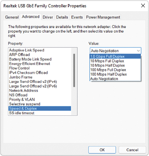
• Figure 19.16 Adjusting the Speed & Duplex settings of a NIC in Windows
Link Lights
Network interfaces have some type of light-emitting diode (LED) status indicator that gives information about the state of the NIC’s link to whatever is on the other end of the connection. Even though you know the lights are actually LEDs, get used to calling them link lights, because that’s the term all network techs use. NICs can have between one and four different link lights, and the LEDs can be any color. These lights give you clues about what’s happening with the link and are one of the first items to check whenever you think a system is disconnected from the network (see Figure 19.17).

• Figure 19.17 Mmmm, pretty lights!
Switches also have link lights, enabling you to check the connectivity at both ends of the cable. If a PC can’t access a network, always check the link lights first. Multispeed devices usually have a link light that tells you the speed of the connection. In Figure 19.18, the left link light for port 2 is lit, but the right link light is not, signifying that the other end of the cable is plugged into a 100BASE-T NIC. Port 1, on the other hand, has both link lights lit. It’s clearly Gigabit.
• Figure 19.18 Multispeed lights
A properly functioning link light is steady on when the NIC is connected to another device. No flickering, no on and off, just on. A link light that is off or flickering shows a connection problem.
Another light is the activity light. This little guy turns on when the card detects network traffic, so it makes an intermittent flickering when operating properly. The activity light is a lifesaver for detecting problems, because in the real world, the connection light sometimes lies to you. If the connection light says the connection is good, the next step is to try to copy a file or do something else to create network traffic. If the activity light does not flicker, you have a problem.
On many NICs, a properly functioning link light is on and steady when the NIC is connected to another device—no flickering indicates a good connection. Some NICs use a single LED to display both the link and activity status, in which case the single LED will flicker with activity. That’s how the NIC shown in Figure 19.17 works. Read the online documentation from the NIC manufacturer’s Web site to determine the meaning of the lights and their steadiness or flickering.
Wake-on-LAN
A popular feature of most NICs is the ability to turn on or wake up a powered-down or sleeping PC. You’ll learn more about power management in Chapter 23, but for now, know that Wake-on-LAN is handy when you want to wake up one or multiple computers that you aren’t physically near. To wake up a PC with Wake-on-LAN, you’ll need to use a second PC to send either a special pattern or a magic packet (a broadcast packet that essentially repeats the destination MAC address many times).
A powered-down or sleeping PC knows to look for this special pattern or packet, at least after configured to do so. Go to the Control Panel and open Network and Sharing Center. Click Manage network connections or Change adapter settings on the left. For all versions of Windows, right-click the adapter and select Properties. Click the Configure button in the Properties dialog box and then select the Power Management tab (see Figure 19.19). To enable Wake-on-LAN, make sure the checkbox next to Allow this device to wake the computer is checked. Optionally, you can select Only allow a magic packet to wake the computer, which will instruct the NIC to ignore everything but magic packets.

• Figure 19.19 Wake-on-LAN settings on the Power Management tab
Wake-on-LAN is very convenient, but it has one nasty downside. As noted in the Properties dialog box, Wake-on-LAN can wake up or turn on laptops using wireless connections, even when they aren’t plugged in or are inside a carrying case. Don’t let your laptop overheat or drain its battery—unless you know that you’ll need it, turn off Wake-on-LAN on your laptop.
QoS
Quality of service (QoS) enables busy networks to prioritize traffic. While we’ll look at QoS from the router’s perspective in Chapter 21, individual systems play an important role in the QoS process by tagging their frames, enabling networking hardware to treat them according to rules defined by network administrators. Support for QoS tagging (or priority) should be enabled by default on most network adapters—but if you need to modify this setting, you can find the VLAN option on the Advanced tab of your NIC’s Properties dialog box (see Figure 19.20).

• Figure 19.20 Network adapter VLAN setting
Configuring IP Addressing
This one’s easy. All operating systems by default will be set for DHCP and acquire IP addressing settings automatically. This is true for both IPv4 and IPv6 configuration options. On the off-chance scenario where you need to configure a client to use a static IP address, you can readily do so.
Connecting to a Switch
Every wired computer connects to a switch, enabling communication with other computers on the network. Networks feature two types of switches, unmanaged and managed. An unmanaged switch is an automatic device. Plug devices into it and they will communicate via MAC addresses with no configuration needed by techs. An unmanaged switch doesn’t do much more than connecting devices.
A managed switch offers a lot of extra features that modern networks use to provide added security and efficiency. Managed switches have an IP address that you can use to configure the options. Figure 19.21 shows a managed switch interface. Dealing with managed switches falls into the realm of CompTIA Network+ and CompTIA Security+ techs, but if you run into a scenario where you need to access such a switch, know that you’ll access it via IP address with either a web browser or via the command line.
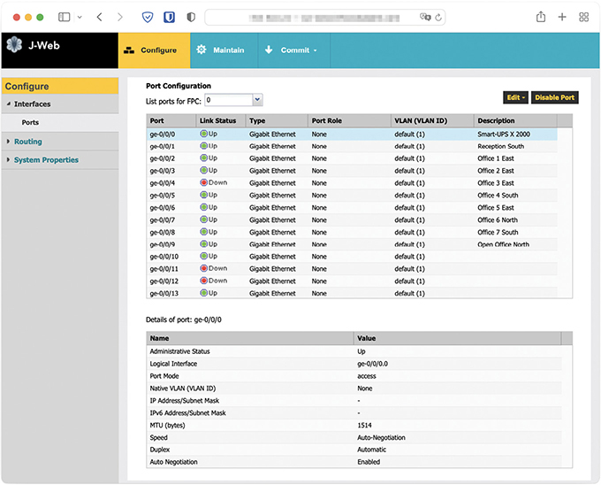
• Figure 19.21 Managed switch interface
Let me give you one great example of the power of managed switches: VLANs. You can use special managed switches to break up or segment a single physical network into two or more distinct networks. Each virtual local area network (VLAN) you create can talk with other computers within the same VLAN, but not to computers on another VLAN. Here’s the cool part. You can have a single switch with, say, 24 computers connected. Normally, all 24 would be on the same network, right? But with a VLAN-capable switch, you can access the management console and assign physical ports to different VLANs. You could assign ports 1 through 12 to VLAN100 and ports 13 through 24 to VLAN200. Computers connected to ports 12 and 13 wouldn’t even know the other computer was there. I’ll save the big discussion of VLANs and cool things you can do with managed switches for the CompTIA Network+ book in your near future.
■ Network Organization and Access Control
Windows systems can share all kinds of resources across your network: files, folders, entire drives, printers, faxes, Internet connections, and much more. To make it easy to find the right resources and control who should be able to access them, networks (including all of their systems and users) need to be organized in some way to make human sense of all of the wires and addresses. This section looks at how resources (such as files and printers) are shared on a network and explores the two main approaches to organizing modern Windows networks: workgroups and domains.
Shared Resources
When you share resources over a network, every OS uses specific network sharing permissions to allow access, restrict access, or deny access to shared resources. These permissions do not have anything to do with file- or folder-level permissions like the NTFS permissions you saw in Chapter 13 (though file- and folder-level permissions do affect the share permissions). They’re also less sophisticated—they don’t, for example, support NTFS features such as inheritance.
On a non-NTFS volume like an optical media disc or a flash-media USB drive, you have three levels of permission when using the default Sharing Wizard: Read, Read/Write, and Owner, which are discussed later in this chapter. With Advanced Sharing (discussed in the upcoming “Sharing Folders with Advanced Sharing” section), the three permission levels are called Read, Change, and Full Control.
If you share a folder on an NTFS drive, as you normally do these days, you must set both the network permissions and the NTFS permissions to let others access your shared resources. You use the network share to share the resource but use NTFS to say what folks can do with that resource. Some good news: This is no big deal! Just set the network permissions to give everyone Full Control, and then use the NTFS permissions to exercise more precise control over who accesses the shared resources and how they access them. Open the Security tab to set the NTFS permissions. We’ll get into the details a little more in the “Organizing with Workgroups” section, next.
Instead of having internal hard drives, each server has access to block storage devices that live in a massive storage array. They’re more or less like local storage devices to the server—it even speaks to them using iSCSI, a network protocol based on the small computer system interface (SCSI) that you encountered back in Chapter 8.
Organizing with Workgroups
Once a network is created, users need to be able to share resources in some organized fashion. Operating systems need a way to determine which users can access resources such as folders and printers and how those resources can be used. Windows networks are organized using workgroups or domains. (These are the Microsoft terms, but the concepts have been adopted by the entire computer industry and apply to macOS and other operating systems.)
Workgroups are an older, simpler approach to the network organizations—so they’re a great place to start. They are also the default for almost every fresh installation of Windows.
By default, all computers on the network are assigned to a workgroup called WORKGROUP. You can see your workgroup name by opening the System applet in Control Panel, as shown in Figure 19.22.

• Figure 19.22 Default workgroup
There’s nothing special about the name WORKGROUP, except that every computer on the network needs the same workgroup name to be able to share resources. If you want to change your workgroup name, you need to use the System applet. In the Computer name, domain, and workgroup settings section on the right, click the Change settings link to open the System Properties dialog box. Then click the Change button to change your workgroup name (see Figure 19.23).

• Figure 19.23 Changing the workgroup name in advanced settings
In macOS, you can change the workgroup name in System Preferences | Network. Click the Advanced button and then click WINS.
Workgroups lack centralized control over the network; all systems connected to the network are equals. This works well for smaller networks because there are fewer users, connections, and security concerns to think about. But what do you do when your network encompasses dozens or hundreds of users and systems? How can you control all of that?
Usernames and Passwords
As you’ll recall from Chapter 13, when you log on to a Windows computer, you need to enter a username and password. Windows makes this easy by giving you a pretty logon interface, as shown in Figure 19.24. Entering a username is identification; putting in a password that matches that username in the OS provides authentication, the process that enables a system to give a user access to system resources.
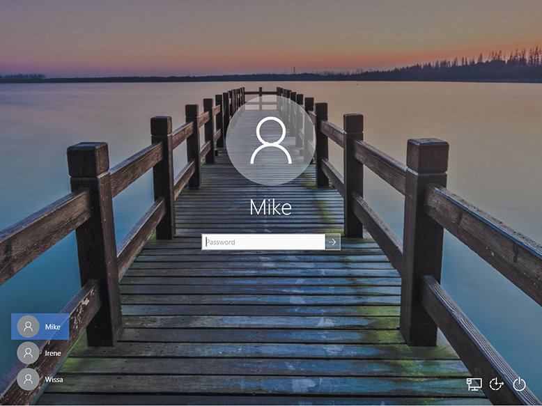
• Figure 19.24 Windows logon screen
The usernames and their passwords are stored in an encrypted format on your computer. Usernames have a number of jobs on your computer, but at this point the job most interesting to us is to give a user access to the computer. Usernames work well when you access your own computer, but these same usernames and passwords are used to access shared resources on other computers in the network—and that’s where we run into trouble. Let’s watch a typical folder share take place on a network of Windows systems.
Sharing Folders with the Sharing Wizard
All personal computers can share folders and printers out of the box. Sharing a folder in Windows is easy, for example, because the Sharing Wizard is enabled by default. Just right-click the folder and select Give access to | Specific people to get to the Choose people to share with dialog box (see Figure 19.25).

• Figure 19.25 Folder sharing in Windows 10
By default, you’ll see every user account that’s currently on this system. You may give an account Read or Read/Write permission, while the person who created the folder is assigned as Owner. The following list describes these permissions:
■ Read You can see what’s in the folder. You may open files in the folder, but you can’t save anything back into the folder.
■ Read/Write Same as Read but you can save files into the folder.
■ Owner Same as Read/Write plus you can set the permissions for other users on the folder.
Sharing Folders with Advanced Sharing
Advanced Sharing enables you to create network shares with more precise control over access to the contents (though in practice techs tend to set everything to Full Control and let NTFS handle authorization at the local level). To create a network share, right-click the folder you want to share and select Properties. Select the Sharing tab—Figure 19.26 shows the Sharing tab for a folder called Music, where I keep high-quality files of some of my favorite albums.

• Figure 19.26 Sharing tab for Music folder
Click Advanced Sharing to open the Advanced Sharing dialog box. Then click Share this folder to make it active (see Figure 19.27). Here you can set the share name—by default it’s the same as the folder name, but it can be unique. You can also limit simultaneous users and add comments, among other things. Click Permissions to get to the last step (see Figure 19.28).

• Figure 19.27 Advanced Sharing dialog box, ready for sharing

• Figure 19.28 Permissions for the about-to-be-created network share
By default, the Everyone group is set to Read permissions, but you have options here. You can add or remove groups or usernames. Click Add to open the Select Users or Groups dialog box where you can search for users/groups currently on the local computer. (That’s important to note, as you’ll see in the next section, “Accessing Shared Folders with Workgroups.”) Also note the other options here.
You have three permission levels—Read, Change, and Full Control—and you can set those permissions to Allow or Deny. Just like you saw with NTFS permissions, Deny always trumps Allow. Advanced Sharing gives you control over what specific user accounts and groups can do with a network share. You could grant Full Control to a user group, for example, but then add a specific user—Bob in Accounting—and Deny Full Control to that user account. That would effectively give everyone in the group (except for Bob) access to the Music share, to add, rename, delete, and so on.
Accessing Shared Folders with Workgroups
So all this sharing seems to work quite nicely, except for one issue: When you log on to a computer, you access a username and database on that computer. The account you access is stored on the local computer; how do you give someone from another computer access to that shared folder? You have to give that other person a valid username and password. We use the nomenclature <computer name><username> to track logons. If you log on to Computer A as Mike, we say you are logged on to ComputerAMike. This nomenclature comes in very handy when networked computers become part of the process.
Figure 19.29 shows Computers A and B. Assume there is a shared folder called Timmy on Computer A and the Mike account has Read/Write permission.
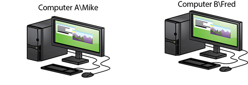
• Figure 19.29 Computers A and B
A person fires up Computer B, logging on as Fred. He opens his Network menu option and sees Computer A, but when he clicks on it he sees a network password prompt (see Figure 19.30).

• Figure 19.30 Prompt for entering username and password
The reason is that the person is logged on as ComputerBFred and he needs to be logged on as ComputerAMike to successfully access this folder. So the user needs to know the password for ComputerAMike. This isn’t a very pretty way to protect usernames and passwords. So what can you do? You have three choices:
1. You can make people log on to shares as just shown.
2. You can create the same accounts (same username and same password) on all the computers and give sharing permissions to all the users for all the shares.
3. You can use one account on all computers. Everyone logs on with the same account, and then all shares are by default assigned to the same account.
Organizing with Domains
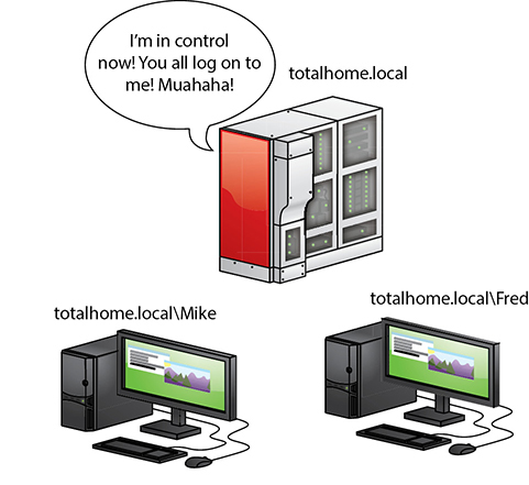
Workgroups work well in smaller networks (<30 computers), but for larger networks, or if you desire a network with more control and security, it’s far better to use a Windows domain—a network organization that centralizes user accounts, passwords, and access to resources. Look at Figures 19.31 and 19.32. In a Windows workgroup, each computer has its own set of local user accounts. In a Windows domain, a computer running Windows Server is configured as a domain controller. A domain controller stores a set of domain accounts. A user logging on to any computer on the domain may use their one domain account to log on to the entire network.

• Figure 19.31 Workgroup

• Figure 19.32 Domain
A Windows domain (which is not the same as a domain in DNS) makes it easy for anyone with a domain account to log on to any computer in the domain with a single account, a process called single sign-on (SSO). Each user does not need a separate local account stored on every computer. User authentication through the single domain account enables access to all machines on the domain, thus the term single sign-on.
If you have a single computer storing all the domain usernames and passwords, why not take it one step higher and store information about the domain, including printer information, computer names, location information—anything you might need to define the entire network? Modern versions of Windows use an Active Directory domain to accomplish these tasks.
To use a domain on a network of Windows machines, for example, you must have a computer running a version of Windows Server (see Figure 19.33) or Linux running Samba. Windows Server is a completely different, much more powerful, and much more expensive version of Windows. You then need to promote the server to a domain controller. This creates the Active Directory.

• Figure 19.33 Windows Server running in command line only core mode
Once a server is set up as a domain controller, creating the Active Directory, each PC on the network needs to join the domain (which kicks you off the workgroup). When you log on to a computer that’s a member of a domain, Windows will prompt you for a username instead of showing you icons for all the users on the network (see Figure 19.34).
• Figure 19.34 Domain logon screen
When using Active Directory, you don’t log on to your computer. Instead, you log on directly to the domain. All user accounts are stored on the domain controller, as shown in Figure 19.35. A lot of domains have names that look like Web addresses, like home.totalsem.com or totalhome.local. Using the previous nomenclature, you can log on to a domain using <domain><domain username>. If the domain totalhome.local has a user account called Mike, for example, you would use totalhome.localMike to log on.
• Figure 19.35 Active Directory network
Domain Organization
Active Directory stores everything about a network. One way to see the Active Directory is to log on directly to the domain controller and run the Active Directory Users and Computers utility—the tool that provides basic Active Directory functions (see Figure 19.36). Note the name of the domain (in this case totalhome.local) on the left side. The folders underneath the domain name show the domain’s organization. Those really aren’t folders. They’re called organizational units (even though they look like folders), but we’ll save that definition for a moment. Here are a few of the more noteworthy folders.

• Figure 19.36 Active Directory Users and Computers
■ Builtin This is where all the built-in domain groups are stored, such as Domain Administrators and Users.
■ Computers Every system, from servers to workstations, is listed in this folder.
■ Domain Controllers It’s always a good idea to have more than one domain controller in case one goes down. This folder lists all of them.
■ Users This area stores all the non-built-in users for the domain.
Domain Administration
Just as individual systems have an administrator account, the domain also has domain administrators. The accounts are extremely powerful and enable you to join a computer to a domain. Certain domain jobs require domain admin rights. Here’s how to deal with adding and removing computers and users from a domain.
To have a computer join a domain, on the Start screen type Control Panel and then press ENTER. Then proceed to System and Security and click System. Under Computer name, domain, and workgroup settings, click Change settings. To change the Computer name, click Change. Under Member of, click Domain, and then type the name of the domain that you want the computer to join, and then press OK. At this point, you will need to restart the computer (see Figure 19.37). Make sure you have access to a Domain account that can join the domain!

• Figure 19.37 Joining a domain
Removing a system from a domain just means accessing the domain controller, going into Active Directory Users and Computers, and right-clicking the computer in question and choosing Properties. Select the Member Of tab, select the unwanted computer, and click the Remove button to remove the computer (see Figure 19.38).

• Figure 19.38 Removing a computer from the domain
There’s no way to promote a local user or group to a domain user or group. A domain admin must create a fresh new domain account on the domain controller using Active Directory Users and Computers. Right-click Users and select New | User (see Figure 19.39) to open the New Object - User dialog box. Figure 19.40 shows the dialog box with user account information filled in.
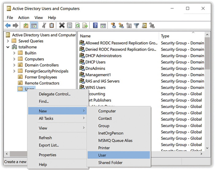
• Figure 19.39 Users context menu options

• Figure 19.40 Adding a new domain account
Domain administrators use the Active Directory Users and Computers utility to clean up account issues. To reset a password, right-click a user account and select Reset Password . . . to open the Reset Password dialog box (see Figure 19.41). Type in a new password, confirm it, and click OK. From the same dialog box, you can select the checkbox to Unlock the user’s account if needed, such as in the case of accidental, multiple mistyped logon attempts. Finally, you can enable or disable a user account from the context menu by selecting—you guessed it—Enable Account or Disable Account.

• Figure 19.41 Reset Password dialog box
There’s a lot of power in a domain account, allowing features you rarely see in a local account. For example, you can add a logon script that runs every time the user logs in that can map network drives, place an information box on the screen, run applications (like anti-malware)—pretty much anything you wish to do. Just add the path and name of the script file under the Profile tab (see Figure 19.42). (Note that CompTIA calls a logon script a login script. It’s the same thing.)
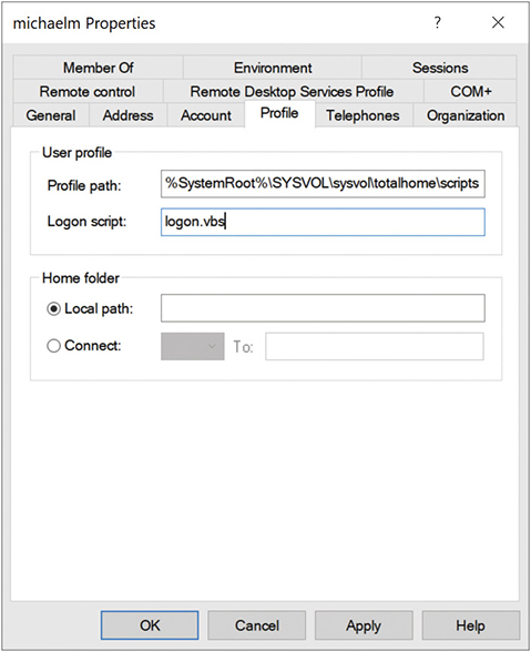
• Figure 19.42 Adding a logon script to a domain account
Another great feature built into Active Directory is the ability to pick where you want to store users’ home folders (such as Pictures, Downloads, Documents, etc.). This requires the use of roaming profiles rather than local profiles. Let me explain. Every time you log on to a computer that’s new to your user account, Windows will set up a new home folder for your domain account on that local machine. It won’t be populated with any of your stuff, though, because it’s a new home folder.
This creates some frustration because users might want to have only one Documents folder, one Downloads folder, one Pictures folder . . . in other words, a single unified home folder. To accomplish this “oneness,” administrators set up roaming profiles on the server. When a user logs on to the domain, the roaming profile applies and the user can access his or her files.
Additionally, administrators can specify the location of users’ home folders, so that when users log on, they access home folders on a remote server rather than the local machine. This process, called folder redirection, helps administrators keep tighter control over network resources.
Just to be clear, administrators handle the processes involved in setting up roaming profiles and folder redirection (and many other cool Active Directory features). CompTIA A+ techs need to know that these features exist so they’re not surprised in the field.
Active Directory enables extremely flexible organization of Active Directory users and computers via the use of organizational units (OUs) that enable you to organize users and computers by function, location, permission…. Whatever makes sense for your organization, you can use OUs to manage those assets.
Figure 19.43 shows an example of a heavily modified Active Directory for the totalhome.local domain. Note the OUs for different locations, inactive accounts, and even printers.

• Figure 19.43 totalhome.local domain
File Servers and Drive Mapping
Sharing individual files and folders that are located on user systems may be all users need to collaborate occasionally, but dedicated file servers are the way to go when many users need round-the-clock access to a single authoritative copy of important files. When users only need access occasionally, they can just directly access the file server (likely after authenticating), but it’s often easier for Windows users that need to interact with a file server constantly to map an unused drive letter to a folder on the file server.
Here’s how to manually configure a mapped drive in Windows. In Windows 11, open File Explorer, click the See More menu, and choose Map network drive. In Windows 10, open File Explorer, click This PC on the left-hand side of the screen, and click Map network drive. In the Map Network Drive dialog box, select the drive letter you want from the drop-down menu, then click Browse and navigate to the folder you’d like to map (as shown in Figure 19.44). You can also choose in the Map Network Drive dialog box whether the drive will be mapped on sign-in and whether it requires different credentials.

• Figure 19.44 Setting up a mapped network drive
Sharing Printers
Sharing printers in Windows follows the same process as sharing files and folders. Assuming that the system has printer sharing services loaded, go to the Devices and Printers settings in the Control Panel and right-click the name of the printer you wish to share. Select Printer properties (not Printers), and then select the Sharing tab (see Figure 19.45). Click Share this printer, add a share name, click OK or Apply, and you’re done.

• Figure 19.45 Giving a name to a shared printer on Windows 10
One of the most pleasant aspects of configuring a system for networking under all versions of Microsoft Windows is the amazing amount of the process that is automated. For example, if Windows detects a NIC in a system, it automatically installs the NIC driver, a network protocol (TCP/IP), and Client for Microsoft Networks. So if you want to share a resource, everything you need is automatically installed. Note that although File and Printer Sharing is also automatically installed, you still must activate it by checking the appropriate checkbox in the Local Area Connection Properties dialog box.
■ Troubleshooting Networks
Once you go beyond a single PC and enter the realm of networked computers, your troubleshooting skills need to take a giant leap up in quality. The secret to finding the right answer to networking problems on the CompTIA A+ exams is to remember that the exams only ask about the skills to get a single computer back on the network. Focus your network troubleshooting answers to scenario questions on getting a single system up and running.
 Cross Check
Troubleshooting Methodology
The troubleshooting methodology presented in CompTIA A+ 1101 objective 5.1 applies to individual computers and components and to networking. You read about this way back in Chapter 1, so cross check your knowledge here.
What are the six steps in the troubleshooting methodology? What should you do first? What should you do to complete a troubleshooting scenario?
As you read through this section, think about the troubleshooting methodology and how it can apply in networking scenarios.
CompTIA likes to ask scenario questions that deal with “no connectivity” or “intermittent connectivity.” Let’s consider two types of connectivity problems: when a computer loses physical connectivity, and when a computer is on the network but can’t access a specific resource.
Repairing Physical Cabling
“The network’s down!” is one of the most terrifying phrases a network tech will ever hear. Networks fail for many reasons, and the first thing to know is that good-quality, professionally installed cabling rarely goes bad, but you need to know what to do when it does. Let’s take a moment now to discuss what to do when you think you’ve got a problem with your physical network.
Symptoms
Physical connectivity interruptions stand out in Windows. Windows displays a circle-backslash symbol over a globe icon in the notification area to show you’re not connected (see Figure 19.46).

• Figure 19.46 Windows no Internet notification icon
If you encounter this problem, first check the obvious. Run ipconfig from the command line. Do you see an APIPA/zeroconf address, like 169.254.15.22? That’s a clear sign of a disconnect between the system and the DHCP server. Is the cable unplugged at the system? At the wall outlet? Then go for the less obvious: Is the NIC disabled in Device Manager? If these checks don’t solve the problem, take a peek on the other side of the cable. If you’re not connected to a running switch, you’re going to get the disconnect errors.
Intermittent connectivity is often the same issue but typically is harder to figure out. Either way, read the next section to see how to get serious about testing for these pesky connectivity problems.
Diagnosing Physical Problems
Look for errors that point to physical disconnection. A key clue that the computer may have a physical problem is that a user gets a “No server is found” error, or tries to use the operating system’s network explorer utility (like Network in Windows) and doesn’t see any systems besides his or her own.
Multiple systems failing to access the network often points to hardware problems. This is where knowledge of your network cabling helps. If all the systems connected to one switch suddenly no longer see the network, but all the other systems in your network still function, you not only have a probable hardware problem but also have a suspect—the switch.
Check the Lights
If you suspect a hardware problem, first check the link lights on the NIC and switch. If they’re not lit, you know the cable isn’t connected somewhere. If you’re not physically at the system in question (if you’re on a tech call, for example), you can have the user check his or her connection status through the link lights or through software.
If the problem system clearly cannot connect, eliminate the possibility of a failed switch or other larger problem by checking to make sure other people can access the network and that other systems can access the shared resource (server) that the problem system can’t see. Inspect the cable running from the back of the computer to the outlet. Finally, if you can, plug the system into a known-good outlet and see if it works. A veteran network tech keeps a long patch cable for just this purpose. If you get connectivity with the second outlet, you should begin to suspect the structured cable running from the first outlet to the switch. Assuming the cable is installed properly and has been working correctly before this event, a simple continuity test will confirm your suspicion in most cases.
Check the NIC
Be warned that a bad NIC can also generate a “can’t see the network” problem. Use the utility provided by the OS to verify that the NIC works. If you’ve got a NIC with diagnostic software, run it—this software will check the NIC’s circuitry. The NIC’s female connector is a common failure point, so NICs that come with diagnostic software often include a special test called a loopback test. A loopback test sends data out of the NIC and checks to see if it comes back. Some NICs perform only an internal loopback, which tests the circuitry that sends and receives, but not the actual connecting pins. A true external loopback requires a loopback plug inserted into the NIC’s port (see Figure 19.47). If a NIC is bad, replace it.
• Figure 19.47 Loopback plug
Cable Testing
The vast majority of network disconnection problems occur at the work area. If you’ve tested those connections, though, and the work area seems fine, it’s time to consider deeper issues.
With the right equipment, diagnosing a bad horizontal cabling run is easy. Anyone running a professional network should own a midrange time-domain reflectometer (TDR) tester such as the Fluke MicroScanner. A TDR sends a signal down the cable, and any sudden change in impedance will cause some of that signal to reflect back. The TDR can then time this reflection and calculate how far down the cable a break is or the total length of a working cable. With a little practice, you can easily determine not only whether a cable is disconnected but also where the disconnection takes place. Sometimes patience is required, especially if the cable runs lack labels, but you will find the problem.
When you’re testing a cable run, always include the patch cables as you test. This means unplugging the patch cable from the PC, attaching a tester, and then going to the telecommunications room. Here you’ll want to unplug the patch cable from the switch and plug the tester into that patch cable, making a complete test, as shown in Figure 19.48.

• Figure 19.48 Cable tester in action
Testing in this manner gives you a complete test from the switch to the system. In general, a broken cable must be replaced. A bad patch cable is an easy fix, but what happens if the horizontal cable is to blame? In these cases, I get on the phone and call my local installer. If a cable is bad in one spot, the risk of it being bad in another is simply too great to try anything other than total replacement.
Toners
It would be nice to say that all cable installations are perfect and that over the years they won’t tend to grow into horrific piles of spaghetti-like, unlabeled cables. In the real world, though, you might eventually find yourself having to locate or trace cables. Even in the best-planned networks, labels fall off ports and outlets, mystery cables appear behind walls, new cable runs are added, and mistakes are made counting rows and columns on patch panels. Sooner or later, most network techs will have to be able to pick out one particular cable or port from a stack.
When the time comes to trace cables, network techs turn to a device called a toner for help. Toner is the generic term for two separate devices that are used together: a tone generator and a tone probe. The tone generator connects to the cable using alligator clips, tiny hooks, or a network jack, and it sends an electrical signal along the wire at a certain frequency. The tone probe emits a sound when it is placed near a cable connected to the tone generator. These two devices are sometimes referred to by the brand name Fox and Hound, a model of toner made by the Triplett Corporation (see Figure 19.49).
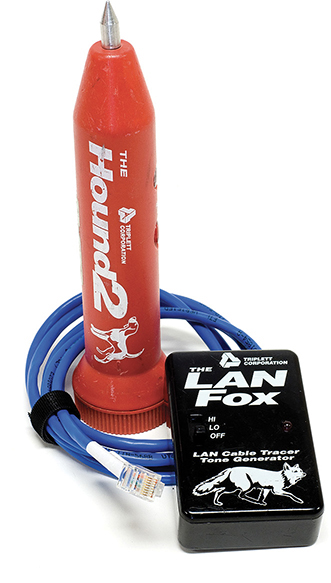
• Figure 19.49 Well used Fox and Hound
To trace a cable, connect the tone generator to the known end of the cable in question, and then position the tone probe next to the other end of each of the cables that might be the right one. The tone probe makes a sound when it’s placed next to the right cable. Some toners have one tone probe that works with multiple tone generators. Each generator emits a separate frequency, and the probe sounds a different tone for each one. Even good toners are relatively inexpensive ($100 or so); although inexpensive toners can cost less than $25, they don’t tend to work well, so spending a little more is worthwhile. Just keep in mind that if you have to support a network, you’d do best to own a decent toner.
Fixing Common Problems
Let’s go back and look at the second possible meaning for a loss in connectivity. It’s very common to try to connect to a shared resource and either fail or find that a shared resource you’ve used time and again has suddenly disappeared. This applies (in this chapter, at least) to local resources—shares on the LAN, shared printers, e-mail server, and so on. Troubleshooting access to unavailable resources is part of a tech’s bread-and-butter job.
Failing to Connect to a New Resource
When you can’t connect to a resource on the first try, it often points to a configuration issue. In most cases, a quick double-check of the sharing system will reveal one of the following problems (and call for the associated solution):
■ You don’t have the right share name? Go check at the serving system.
■ You don’t have the required username/password? Ask someone who might have this knowledge, or double-check that your account has access.
■ You don’t have permission to use/access/connect to the shared resource? Make sure you have the correct permissions.
■ You may need a forced Group Policy update if you’re in an Active Directory domain. Group Policy updates may take a little while to propagate. The gpresult and gpupdate commands we took a look at in Chapter 15 can help you view the active policy settings and force an update if necessary.
■ The folder or printer isn’t shared? Share it!
■ The folder or printer doesn’t exist? Make sure the serving system still hosts the folder you want. Install the network printer if you haven’t yet.
Failing to Connect to a Previously Used Resource
If you suddenly can’t connect to a resource that you’ve used many times before, go with the easy answers first:
■ Check that you can see the resource using Network.
■ Check that the serving system is on.
■ Check that the computer is physically connected to the serving system.
The net Command
Windows enables you to view a network quickly from the command line through the net command. This works great when you plug into a network for the first time and, naturally, don’t know the names of the other computers on that network. To see the many options that net offers, type net at a command prompt and press ENTER. The view and use options offer excellent network tools.
You can think of net view as the command-line version of Network. When run, net view returns a list of Windows computers on the network:

Once you know the names of the computers, you type net view followed by the computer name. The net view command will show any shares on that machine and whether they are mapped drives:
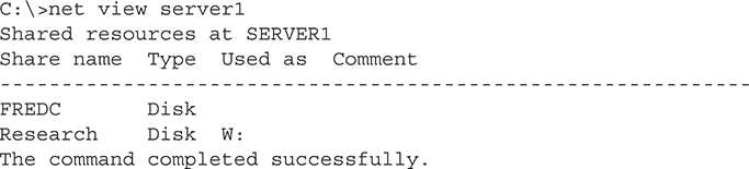
The net use command is a command-line method for mapping network shares. For example, if you wanted to map the Research share shown in the previous example to the X: drive, you simply run
C:>net use x: \server1 esearch
This will map drive X: to the Research share on the SERVER1 computer. Mapping a drive means the drive will show up in File Explorer as a selectable resource, just like a local drive.
net config workstation
It’s quick and easy!
The nbtstat Command
The nbtstat command is an old command-line utility that predates Windows. It stands for NetBIOS over TCP/IP Statistics. Many versions ago, Windows used NetBIOS for many aspects of LAN file sharing, and even though NetBIOS is long gone, bits of NetBIOS hang on as a way for Windows to resolve host names on the network when a DNS server is not available.
While not covered on the CompTIA A+ Exam, nbtstat can still provide insight when troubleshooting naming issues in small workgroups. Here are a couple of usage examples; to see what your computer’s NetBIOS name is, use the nbtstat -n command:

You can also query a remote machine by IP to find out its NetBIOS name with nbtstat -A (note the uppercase “A”; use a lowercase “a” if you know the machine’s NetBIOS name already):

Finally, you can see all the names that NetBIOS has in its local cache with nbtstat -c:

Because the cache is temporary, you may find that it is empty if you haven’t browsed your LAN or interacted with another machine recently.
Chapter 19 Review
■ Chapter Summary
After reading this chapter and completing the exercises, you should understand the following about local area networking.
Explain the basics of interconnecting networks with TCP/IP
■ TCP/IP is the primary protocol of most modern networks, including the Internet.
■ IP introduces its own logical addressing scheme where the addresses are not tied to the hardware (as MAC addresses are). In this hierarchical addressing scheme, devices high up in a hierarchy know how to direct traffic to addresses within the hierarchy.
■ Routers interconnect LANs. A default gateway is the port on your router that connects to your LAN.
■ Any network address must provide two pieces of information: it must uniquely identify the machine and it must locate that machine within the larger network. Many systems today still rely on the Internet Protocol version 4 (IPv4) addressing scheme. In a TCP/IP network, the IPv4 address identifies the PC and the network on which it resides.
■ Part of every IP address identifies the network (the network ID), and another part identifies the local computer (the host ID, or host) on the network. The subnet mask is a value that a NIC uses to distinguish which part of the IP address identifies the network ID and which part of the address identifies the host. Every computer on a single LAN must have the same network ID and a unique host ID.
■ Originally, subnets fell into “classes,” such as A, B, or C, determined by the corresponding octet in the subnet mask. A Class C address had a subnet mask of 255.255.255.0. A Class B address, in contrast, had a subnet mask of 255.255.0.0. The latter class left two full octets (16 bits) just for host numbers. A Class A address had a subnet mask of 255.0.0.0.
■ The current system is called Classless Inter-Domain Routing (CIDR). With CIDR, network techs refer to the subnet mask by the number of ones it contains, such as /24 or /26.
■ IPv6 extends the 32-bit IP address space to 128 bits, allowing up to 2128 addresses. The familiar 32-bit IPv4 addresses are written as 197.169.94.82, using four octets. The 128-bit IPv6 addresses are written like this: 2001:0000:0000:3210:0800:200c:00cf:1234. A complete IPv6 address always has eight groups of four hexadecimal characters.
■ Every computer using IPv6 has a link-local address to handle local networking. Systems connected to the Internet have one or more global addresses. The first 48 to 64 bits of an IPv6 address is the prefix length, used to determine whether to send packets to a local MAC address or to the default gateway to send the packets out to the Internet. The last, randomly generated 64 bits of an address—the interface ID—uniquely identifies the computer.
■ Special computers, called Domain Name System (DNS) servers, keep databases of IP addresses and their corresponding names (and store other related information). This enables people to use names rather than IP addresses to access remote resources.
■ DNS has different record types for different purposes. A and AAAA are address records that associate names with IPv4 and IPv6 addresses, respectively. MX records specify to which server e-mail for your domain should be sent. TXT records are used for many purposes, including spam management (via DKIM, SPF, and DMARC).
■ TCP/IP requires that several settings are properly configured before you can connect to a network. A network administrator should configure these for you. These settings include your IP address, subnet mask, default gateway, DNS settings, and DHCP settings.
■ A DHCP server temporarily leases out addresses from a range that is known as its pool or scope. You can use a DHCP reservation to tell DHCP to set aside an IP address for a specific client (usually a server).
■ When you want to be positive that the data moving between two systems gets there in good order, use a connection-oriented application. If it’s not a big deal for data to miss a bit or two, then connectionless is the way to go. The connection-oriented protocol used with TCP/IP is called the Transmission Control Protocol (TCP). The connectionless one is called the User Datagram Protocol (UDP).
■ Windows includes several tools for testing and managing TCP/IP, including ping, ipconfig, nslookup, and tracert. macOS and Linux use ifconfig or ip, dig, and traceroute.
■ By default, TCP/IP is configured to receive an IP address automatically from a DHCP server on the network (and automatically assign a corresponding subnet mask).
■ Modern operating systems support a feature called Automatic Private IP Addressing (APIPA) in Windows or zeroconf in other operating systems that automatically assigns an IP address to the system when the client cannot obtain an IP address automatically.
Install and configure wired networks
■ To establish network connectivity, you need to have three things in place: a connected NIC, properly configured IP addressing, and a switch. When you install a NIC, by default Windows installs upon setup the TCP/IP protocol (configured for DHCP), the Client for Microsoft Networks, and File and Printer Sharing for Microsoft Networks.
■ Computers need properly configured IP addressing to connect to a network. DHCP handles this for the most part. Also, computers in a wired network need to connect to a switch—unmanaged or managed—to interconnect with other computers on the network.
Understand network organization and access controls
■ When you share over a network, every OS uses specific network sharing permissions to allow or restrict access to shared resources. These less-sophisticated permissions do not have anything to do with file- or folder-level permissions like you find in Windows with NTFS. If you share a folder on an NTFS drive, as you normally do these days, you must set both the network permissions and the NTFS permissions to let others access your shared resources.
■ When sharing a folder on an NTFS drive, you must set the network permissions to give everyone Full Control, and then use the NTFS permissions (on the Security tab) to exercise more precise control over who accesses the shared resources and how they access them.
■ Once a network is created, users need to be able to share resources in some organized fashion. Operating systems need a way to determine which users can access resources such as folders and printers and how those resources can be used. Modern Windows networks are organized using workgroups or domains.
■ A workgroup enables computing devices in the same workgroup to communicate and share folders and data. Workgroups use local security; in practice, this means that to access shared folders on a computer, you need a valid user account on that machine. Workgroups work fine for small networks.
■ An Active Directory domain centralizes user accounts, passwords, and access to resources on a network via a domain controller. Valid domain accounts log in once to the domain and have access to all resources on the domain. This is called single sign-on.
■ All versions of Windows share folders in basically the same manner. Right-click any folder, choose Properties, and then select the Sharing tab. Click the Advanced Sharing button, then click the Share this folder radio button and type a share name.
■ More robust file sharing typically involves dedicated file servers. Windows users who need regular access to these files may use File Explorer to map an unused drive letter on their local system to a folder on the file server.
■ To share a printer, open Devices and Printers in the Control Panel, right-click the name of the printer you wish to share, select Printer properties, select the Sharing tab, and then click Share this printer.
Troubleshoot wired networks
■ Look for errors that point to physical disconnection. A key clue that you may have a physical problem is that a user gets a “No server is found” error or tries to use the operating system’s network explorer utility (like Network in File Explorer) and doesn’t see any systems besides his or her own.
■ Run ipconfig (or ifconfig in macOS and Linux) from a command line or terminal window. An APIPA/zeroconf address (like 169.254.15.22) points to some kind of disconnection.
■ If you suspect a hardware problem, first check the link lights on the NIC and switch. If they’re not lit, you know the cable isn’t connected somewhere. If you’re not physically at the system in question (if you’re on a tech call, for example), you can have the user check his or her connection status through the link lights or through software.
■ A bad NIC can also generate a “can’t see the network” problem. Use the utility provided by your OS to verify that the NIC works. If you’ve got a NIC with diagnostic software, run it—this software will check the NIC’s circuitry.
■ A loopback test sends data out of the NIC and checks to see if it comes back. Some NICs perform only an internal loopback, which tests the circuitry that sends and receives, but not the actual connecting pins. A true external loopback requires a loopback plug inserted into the NIC’s port.
■ A TDR measures impedance in network cabling. If the tester measures any impedance, something is wrong with the cable.
■ When you’re testing a cable run, always include the patch cables as you test. This means unplugging the patch cable from the PC, attaching a tester, and then going to the telecommunications room.
■ When the time comes to trace cables, network techs turn to a device called a tone probe or toner probe for help. The tone generator connects to the cable using alligator clips, tiny hooks, or a network jack, and it sends an electrical signal along the wire at a certain frequency. The toner probe emits a sound when it is placed near a cable connected to the tone generator. These two devices are sometimes referred to by the brand name Fox and Hound, a popular model of toner.
■ Windows enables you to view a network quickly with the net command. Additionally, the nbtstat command can provide insight when troubleshooting naming issues in small workgroups.
■ Key Terms
Active Directory
activity light
Automatic Private IP Addressing (APIPA)
Classless Inter-Domain Routing (CIDR)
default gateway
DHCP server
dig
DNS server
Domain Name System (DNS)
Dynamic Host Configuration Protocol (DHCP)
full-duplex
half-duplex
host ID
Internet Protocol version 4 (IPv4)
Internet Protocol version 6 (IPv6)
lease
link light
link-local address
loopback plug
loopback test
net command
network ID
network protocol
nslookup
ping
router
static IP address
subnet mask
tone generator
tone probe
toner
toner probe
tracert
traceroute
Transmission Control Protocol (TCP)
Transmission Control Protocol/Internet Protocol (TCP/IP)
User Datagram Protocol (UDP)
wide area network (WAN)
workgroup
■ Key Term Quiz
Use the Key Terms list to complete the sentences that follow. Not all terms will be used.
1. __________________ networks group users and devices using the concept of organizational units.
2. The command-line utility called __________________ enables one machine to check whether it can communicate with another machine.
3. A NIC uses a value called the __________________ to distinguish which part of the IP address identifies the network ID and which part of the address identifies the host.
4. A computer on a(n) __________________ network gets a 32-bit address.
5. A computer on a(n) __________________ network gets a 128-bit address.
6. A(n) __________________ is a device that has at least two IP addresses: one that connects to your LAN’s switch and one that connects to the “next network.”
7. Special computers, called __________________ servers, keep databases of IP addresses and their corresponding names.
8. A(n) __________________ server enables computers to obtain IP addresses automatically.
9. When troubleshooting a NIC, you’ll need to crawl behind your computer and look for a __________________, which should be on or blinking.
10. To test a possibly broken Ethernet port, plug in a(n) __________________.
■ Multiple-Choice Quiz
1. Everything worked fine on your 1000BASE-T network yesterday, but today no one can connect to the server. The server seems to be in good running order. Which of the following is the most likely problem?
A. Someone changed all of the passwords for server access.
B. A switch is malfunctioning.
C. Someone’s T-connector has come loose on the bus.
D. The server’s cable is wired as ANSI/TIA 568A and all of the others are wired as ANSI/TIA 568B.
2. Simon’s system can’t contact a DHCP server to obtain an IP address automatically, but he can still communicate with other systems on his subnet. What feature of Windows makes this possible?
A. Subnet masking
B. Default gateway
C. APIPA
D. Client for Microsoft Networks
3. Which of the following is the correct net syntax for discovering which network shares on a particular server are mapped on your computer?
A. net view \fileserver
B. net \fileserver
C. net map \fileserver
D. net share \fileserver
4. A small device that enables you to test a NIC’s circuitry is called?
A. Loopback plug
B. Port tester
C. Multimeter
D. Integrated network and logic probe
5. Steven’s Windows system can’t connect to the Internet, and he comes to you, his PC tech, for help. You figure out that it’s a DHCP problem. What program should you run to troubleshoot his DHCP problem from the client side?
A. ipconfig
B. ifconfig
C. config
D. dhcp /review
6. You are down under your desk organizing some wires when you notice that the activity light on your NIC is blinking erratically. Is there a problem?
A. Yes, the activity light should be on steadily when the computer is running.
B. Yes, the activity light should be blinking steadily, not randomly.
C. No, the light blinks when there is network traffic.
D. No, the light blinks to show bus activity.
7. What is a common symptom of a bad network cable?
A. Rapidly blinking link lights
B. No link lights
C. Solid on link lights
D. Steady blinking link lights
8. What command-line utility would you run to show a list of network computers?
A. net send
B. show net_servers
C. net use
D. net view
9. What Windows-based command would you use to view the path taken by a TCP/IP packet?
A. ping
B. traceroute
C. tracert
D. nslookup
10. Which of the following is a legitimate IPv6 address?
A. 192.168.1.25
B. fedc::cf:0:ba98:1234
C. fedc::cf:0ba98:1234
D. fedc::cf:0:ba98:12345
11. You are trying to locate which patch cable in the main switch traces back to a particular computer. Which tool should you use?
A. Toner probe
B. Cable tester
C. Punchdown tool
D. Butt set
12. Which of the following describe an IPv4 address? (Select three.)
A. Uses decimal, not hexadecimal numbers
B. Uses periods, not colons, as separators
C. Uses four octets
D. Uses eight sets of characters
13. Which tool in Linux enables you to determine exactly what information the DNS server is giving you about a specific host name?
A. ipconfig
B. ifconfig
C. nslookup
D. ping
14. What benefit does full-duplex offer?
A. It enables NICs to send and receive signals at the same time.
B. It enables NICs to send data twice as fast.
C. It enables NICs to receive data twice as fast.
D. It enables a switch to connect to both coaxial and fiber optic cables.
15. Which is a brand name of toner probe and tone generator?
A. TDR
B. UTP
C. UDP
D. Fox and Hound
■ Essay Quiz
1. You are a tech for a small company and you get a call from Jessica, who cannot access the network anymore from her workstation. What techniques would you use to help troubleshoot her system and get her back working?
2. There are different classifications of IP addresses and different ways to assign them. Write a short essay on the difference between old Class A, B, and C addresses. Explain how the current CIDR system differs from the older class system.
Lab Projects
• Lab Project 19.1
This chapter described how Windows automatically generates an IP address if the computer system cannot contact a DHCP server. Experiment with this idea. If you have a network of Windows PCs that you can play with, make sure there is no DHCP server on the network. Use ipconfig and see what your IP address is, and try sharing it and pinging other systems. Try to share resources and access shared resources on other machines in the lab.
• Lab Project 19.2
Nearly every hardware manufacturer wants you to upgrade to their latest networking gear and they keep adding new features to entice you. Do a search through the bigger companies’ product lists and compare the Linksys, NETGEAR, Ubiquiti, and D-Link devices:
• Lab Project 19.3
The Internet is a big, sprawling place with big routers that move packets from place to place around the world. Using the tracert command in Windows or the traceroute command in macOS or Linux, see how many hops it takes to get to various Web sites around the world.