chapter 5
Firmware
“Into the BIOS”
—DURAN DURAN, “VIRUS,” ASTRONAUT

In this chapter, you will learn how to
■ Define and explain the function of firmware, UEFI, BIOS, CMOS, ROM
■ Distinguish among various system setup utility options
■ Troubleshoot using the power-on self-test (POST)
■ Maintain BIOS/UEFI settings
In Chapter 3 you saw how the address bus and data bus connect RAM to the CPU via the memory controller to run programs and transfer data. Assuming you apply power in the right places, you don’t need anything else to make a simple computer. The only problem with such a simple computer is that it would bore you to death—there’s no way to do anything with it! A PC needs devices such as keyboards and mice to provide input, and output devices such as monitors and speakers to communicate the current state of the running programs to you. A computer also needs permanent storage devices, such as solid-state drives, to store programs and data when you turn off the computer.
This chapter discusses in detail the software that controls a PC at its core. We’ll start with a couple of sections on why and how it all works, and then we’ll look at hardware and self-testing circuits. The chapter finishes with the finer points of maintaining this essential programming and hardware.
1101
■ We Need to Talk
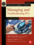
For a keyboard or a monitor or a hard drive to work with a CPU, they must communicate via some kind of physical connection. More than that, these peripherals (usually) can’t connect directly to the CPU. This communication requires a controller, a chip that connects the device to the CPU (see Figure 5.1).

• Figure 5.1 A controller chip acts as an interface.
Getting the CPU to communicate with a controller starts with a physical interconnection—a communication bus (that means wires) that enables the CPU to send commands to and from devices. To make this connection, let’s extend the data bus and the address bus throughout the motherboard, connecting all of the computer’s controllers to the CPU (see Figure 5.2).

• Figure 5.2 Data bus and address bus extended
Early motherboards were packed with controller chips. Figure 5.3 shows a very early motherboard, absolutely covered in controller chips (as well as many other chips).

• Figure 5.3 Early motherboard, loaded with controller chips
Starting around 1990, chip manufacturers began to combine multiple controller chips into specifically designed chipsets to reduce chip count and to standardize communication between the CPU and devices. Early chipsets such as the Intel 430VX shown in Figure 5.4 consisted of two paired chips called the northbridge and southbridge.

• Figure 5.4 Ancient 430VX chipset showing northbridge and southbridge
Chipsets were in pairs for many years, roughly from 1990 to around 2010. Today’s CPUs have controllers built into the CPU itself, such as the memory and display controllers. With so many chipset functions now built into the CPU, almost all chipsets are now a single chip—Intel’s name for this chip is Platform Controller Hub (PCH). Figure 5.5 shows where the CPU and PCH are located on an Intel motherboard. AMD (and most of the tech industry) still refers to the single chip as the chipset, even though it’s no longer a “set” of chips.

• Figure 5.5 Intel CPU and PCH

The chipset extends the data bus to every device on the PC. The CPU uses the data bus to move data to and from all the devices of the PC. Data constantly flows on the data bus among the CPU, chipset, RAM, and other devices on the PC (see Figure 5.6).

• Figure 5.6 Everything connecting
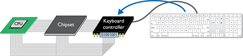
The concept that the CPU uses the address bus to talk to the devices isn’t difficult to fathom, but how does the CPU know what to say to them? How does it know, for example, all the patterns of ones and zeros to place on the address bus to tell the hard drive it needs to send a file? Let’s look at the interaction between the keyboard and CPU for insight into this process.
 Cross Check
Address Bus
You learned about the address bus in Chapter 3, so flip back and see if you can answer these questions. What’s the difference between a 32- and 64-bit address bus? How does the CPU decide which pattern of ones and zeros on the address bus goes to which line of RAM?
Talking to the Keyboard
Let’s step back a moment and consider a world without chipsets, where every device had its own controller. The keyboard provides a great example of how the buses and support programming help the CPU get the job done. In early computers, the keyboard connected to the data bus via a special chip known as the keyboard controller. Don’t bother looking for this chip on your motherboard—chipsets long ago replaced keyboard controller chips.
Even though dedicated keyboard controller chips no longer exist, the way the keyboard controller functions with the CPU has changed only a small amount in the past decades, making it a perfect tool to illustrate how the CPU talks to a device.
The keyboard controller was one of the last single-function chips to be absorbed into the chipset. Figure 5.7 shows a typical keyboard controller from those days. Electronically, it looked like Figure 5.8.

• Figure 5.7 A dedicated keyboard chip on a pre-1990 motherboard

• Figure 5.8 Electronic view of the keyboard controller
Every time you press a key on your keyboard, a scanning chip in the keyboard notices which key you pressed. Then the scanner sends a coded pattern of ones and zeros—called the scan code—to the keyboard controller. Every key on your keyboard has a unique scan code. The keyboard controller stores the scan code in its own register. Does it surprise you that the lowly keyboard controller has a register similar to a CPU? Lots of chips have registers—not just CPUs (see Figure 5.9).
• Figure 5.9 Scan code stored in keyboard controller�s register
How does the CPU get the scan code out of the keyboard controller? While we’re at it, how does the CPU tell the keyboard to type capital letters if CAPS LOCK is on or to turn the NUM lock LED (light-emitting diode) on and off, to mention just a few other jobs the keyboard needs to do for the system? The point is that the keyboard controller must be able to respond to multiple commands, not just one.
The keyboard controller accepts commands exactly as you saw the CPU accept commands in Chapter 3. Remember when you added 2 to 3 with the 8088? You had to use specific commands from the 8088’s codebook to tell the CPU to do the addition and then place the answer on the external data bus. The keyboard controller has its own codebook—much simpler than any CPU’s codebook, but conceptually the same. If the CPU wants to know what key was last pressed on the keyboard, the CPU needs to know the command (or series of commands) that orders the keyboard controller to put the scan code of the letter on the external data bus so the CPU can read it.
The CPU doesn’t magically or otherwise automatically know how to talk with any controller; it needs some sort of programming—a codebook of commands, ready to go in memory, to speak to that particular controller. We call this codebook a device driver.
A device driver is code, sitting on the PC’s mass storage, that’s loaded into memory as your operating system starts. As mentioned above, a device driver is a codebook that contains all the commands necessary to talk to whatever device it was written to support. All operating systems store hundreds of device drivers (the number of device drivers varies wildly). The operating system loads the device drivers on boot. Without a correct device driver, your operating system cannot run that specific controller.
Want to see your device drivers? In Windows you open Device Manager to see all your loaded device drivers. Figure 5.10 shows my system’s Device Manager with details on a single device.

• Figure 5.10 Windows device drivers seen from the Device Manager utility
Whoa. Wait! We got a HUGE problem here! How can your operating system boot up and load device drivers if the system doesn’t even know how to talk to the mass storage where the operating system and device drivers are stored (see Figure 5.11)? Even if the operating system could somehow magically not need a device driver, how do you tell the system where the operating system is located to load it? What if you like to install multiple operating systems—how does the system know which operating system to start?
• Figure 5.11 How do you talk to a device without a device driver?
Forget all about the device drivers for a second and consider some other actions that might be really nice at boot-up. Would you like some security, like a password that comes even before the operating system loads? How about anti-malware that stops a virus from acting like your operating system at boot time and taking over your computer? Perhaps you’d like to overclock your system—where do you go to tweak the CPU speed or the CPU multiplier?
If we want to do actions such as these, then we need some code to tell the CPU about this. This code isn’t in the operating system, as all this must be done before the OS even loads! We need to add some code, some “device drivers before the device drivers,” to make all these actions take place. Not only do we need to create this code, we need to physically place it somewhere so the CPU can access and run the code before the system boots up. To sum up, we need this code to perform three functions:
1. Communicate to the mass storage and a few other controllers on the motherboard. Once that function is established, we can control enough hardware to perform the next two items.
2. Develop some kind of interface that lets us add to, configure, and change boot-time features of our systems, like boot order, security, and much more. We’ll need some more of those basic device drivers for our monitor, keyboard, and maybe mouse to input those changes and see what we are doing. We might even need network drivers if we want to do cool actions like boot from another host on a network.
3. Tell the CPU where to look for an operating system so the system can boot into that operating system. If there’s more than one bootable device, we need to tell the CPU which one to go to first.
(There are a lot more functions than just those three, but these will get us started on our learning path.)
Luckily for us, the code to do these functions exists on every computer—and has been since the first PCs back in the early 1980s. The code exists on your motherboard on a chip. OK, but what chip technology should the motherboard use? RAM won’t work, because all the data is erased every time we turn off the computer. We cannot use a hard drive, as that requires a driver. We need some type of permanent program storage device that does not depend on other peripherals to work. It must plug directly into the address/system bus so the CPU can talk to it. And we need that storage device to sit on the motherboard. What we need is called ROM.
ROM
Motherboards store all the magical bits of code described in the previous section on a special type of device called a read-only memory (ROM) chip. A ROM chip stores code exactly like RAM, but with two important differences. First, ROM chips are nonvolatile, meaning that the information stored on ROM isn’t erased when the computer is turned off. Second, traditional ROM chips are read-only, meaning that once you store a program on one, you can’t change it unless you go through a specific reprogramming process. There are many types of ROM, but for the past 20 years or so, all motherboards use a type of ROM called flash ROM. Figure 5.12 shows a typical flash ROM chip on a motherboard.

• Figure 5.12 Typical flash ROM

Great! We now have a flash ROM chip sitting on every motherboard. Now we need to load it with firmware to solve the three functions described in the previous section. Enter something amazing called UEFI!
UEFI
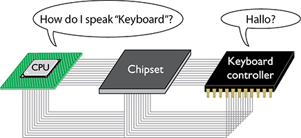
Modern systems use firmware programming called the Unified Extensible Firmware Interface (UEFI). UEFI is a programming standard that defines how we configure utilities that every system needs: device drivers, boot support, and system setup—all on the motherboard’s flash ROM chip. UEFI essentially provides the programming that enables the CPU to communicate with other hardware. You’ve seen UEFI in action during a system’s boot, although it’s easily missed if you’re not paying attention (see Figure 5.13).

• Figure 5.13 UEFI data appearing during the boot-up of a desktop system.
The correct term for UEFI “device drivers” is services. UEFI provides services to support most of the hardware on your system. These services don’t support as many features as true device drivers, but they are good enough to support configuring and booting a system.
BIOS
All current systems use UEFI and have since around 2010. However, before UEFI was invented these functions were known as BIOS (basic input/output system). BIOS was very ancient, originally designed to be run on the Intel 8088 CPU back in 1981. System makers are very conservative, so BIOS hung on long after everything else on a typical PC was upgraded and improved. UEFI has completely replaced BIOS but the term BIOS is still out there and very commonly used. For example, most techs continue to call the system’s UEFI the BIOS. Maybe PC techs are also conservative? Bottom line? Be ready to use either word interchangeably.
■ CMOS and the System Setup Utility
Flash ROM is read-only, but there’s a problem: every UEFI needs a tiny bit of writable memory. UEFI knows you have RAM, but how much RAM does UEFI need? You want to add a boot-up password, so where do you tell UEFI to store that password? This writable memory is a tiny bit of specialized RAM hooked up to a small battery to keep it working when the PC is off and unplugged. We call this memory complementary metal-oxide semiconductor (CMOS). Today the CMOS is built into the chipset, but back in the old days CMOS was a dedicated chip (see Figure 5.14).

• Figure 5.14 Old-style CMOS chip
If the data stored in CMOS about a piece of hardware (or about its fancier features) is different from the specs of the actual hardware, the computer cannot access that piece of hardware (or use its fancier features). It is crucial that this information be correct. If you change any of the previously mentioned hardware, you must update CMOS to reflect those changes. You need to know, therefore, how to change the data in CMOS.
Every UEFI comes with a system setup utility that enables you to access and modify CMOS data. On a completely new system, with no operating system installed, you’ll see something like the system setup utility shown in Figure 5.15. After the OS is installed, these screens effectively disappear. I’ll show you how to access them in a little bit.

• Figure 5.15 Gigabyte system setup utility
Touring the System Setup Utility
Every BIOS/UEFI maker’s system setup utility looks a little different. Some are graphical like the one shown in Figure 5.15 and some are more textual, but don’t let that confuse you. They all contain basically the same settings; you just have to be comfortable poking around the different interfaces. To avoid doing something foolish, do not save anything unless you are sure you have it set correctly.
Accessing System Setup
You access the system setup utility by pressing one or more utility-specific keys when the system is booting. Turn off your system and then turn it on again. Watch the screen closely! On some systems you’ll read text on the screen telling you what key(s) to press, as shown in Figure 5.16. Many boot screens do not show up like that figure!
• Figure 5.16 Boot screen with system setup instructions
There’s no standard key to press here, but the two most common keys are DELETE and F2. When in doubt just do a Web search for the right keys for your system. Figure 5.17 shows the instructions to access the system setup on a Microsoft Surface (from the Microsoft Web site).

• Figure 5.17 Microsoft.com instructions for how to access system setup on a Surface device
Don’t be afraid to experiment. There’s no danger in trying combinations until something works! If you press a key and the system boots to an operating system, then you’re either too slow or pressing the wrong key. No worries—just reboot the system and try again.
Let’s start by touring a graphical system setup. Figure 5.18 shows a typical, simple graphical setup screen. This particular system setup utility has two modes: EZ and Advanced (not all system setups offer this EZ/Advanced option thing, but it’s nice when they do).

• Figure 5.18 ASUS UEFI system setup utility
Click the option to go into Advanced Mode and you’ll get a much more versatile utility (see Figure 5.19) for changing the interface configurations. The Main tab offers some BIOS component information, such as the amount of RAM and speed of CPU, plus a couple of options to modify the language and date and time.

• Figure 5.19 Main tab
The Main tab (not all system setups have a Main tab option, but many do) enables you to configure passwords by setting an administrator or user password. (The default for the pictured UEFI BIOS is Access Level: Administrator. Click the Security option to change access information. UEFI setup screens differ somewhat, but you’ll find similar options in all of them.)
An administrator password locks or unlocks access to the system setup utility. A user password locks or unlocks the computer booting to an operating system. Set a BIOS/UEFI password when you encounter a scenario like installing computer kiosks at a convention or installing systems in a public library. A BIOS/UEFI password is required to login into a computer’s BIOS/UEFI to stop casual miscreants from messing with your accessible systems.
Things get far more interesting in the other tabs. Selecting the Ai Tweaker tab, for example, enables you to delve into the Dark Arts of overclocking both the CPU and RAM (see Figure 5.20). You can change the clock multiplier, clock speeds, voltages, and more here. This is a great place to go to fry a new CPU!

• Figure 5.20 Ai Tweaker tab
The Advanced tab (see Figure 5.21) gives component information about CPUs, hard drives and optical drives, and all the built-in components, such as USB ports. In this tab, as you drill down to each subcategory, you can configure drive settings, enable and disable devices, and more.

• Figure 5.21 Advanced tab
The Boot tab (see Figure 5.22) enables you to adjust boot settings. You can select devices to boot by priority, setting the boot sequence used by the motherboard. (See “The Boot Process” later in this chapter for more information.) You can determine how the system will react/inform if booting fails, and more.
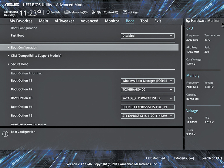
• Figure 5.22 Boot tab
The Tool tab (see Figure 5.23) has a couple of very important features. The ASUS EZ Flash 3 Utility enables you to update the motherboard firmware. See the “Flashing the ROM” section later in this chapter for more details. The Tool tab also shows RAM information. That’s the SPD option (for serial presence detect) you should recognize from Chapter 4.

• Figure 5.23 Tool tab
So you don’t start thinking that all system setups look the same, let’s switch to a UEFI motherboard on an Intel-based portable computer with a more text-based interface. This isn’t nearly as pretty as the first system setup but it still does the job. As we go through the screens, pay attention to the options listed on the screen. I’ll call out features that the graphical AMD-based UEFI didn’t have.
The Information tab (see Figure 5.24) offers straightforward information about the CPU and RAM amount and cryptic information about the hard drive. Other tabs do more.

• Figure 5.24 Information tab
The Configuration tab (see Figure 5.25) shows a number of built-in devices that you configure or enable/disable here. Because this is a laptop, it has an option to turn on/off wireless networking capabilities.
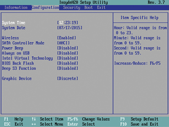
• Figure 5.25 Configuration tab
There are two interesting options here that are covered in detail in other chapters but warrant a brief discussion now. The Intel Virtual Technology option enables or disables virtualization support for virtual machines. A virtual machine is a powerful type of program that enables you to run a second (or third or fourth) software-based machine inside your physical PC. It re-creates the motherboard, hard drives, RAM, network adapters, and more, and is just as powerful as a real PC. To run these virtual machines, however, you’ll need a very powerful PC—you are trying to run multiple PCs at the same time, after all.
To support this, CPU manufacturers have added hardware-assisted virtualization. Intel calls its version Intel Virtualization Technology (Intel VT for short), and AMD calls its version AMD Virtualization (AMD-V) technology. This technology helps the virtual machines use your hardware more efficiently and is controlled by the BIOS. This feature is disabled by default in BIOS, so if your virtual machine requires hardware-assisted virtualization, you’ll need to enable it here.
This particular laptop has built-in graphics courtesy of the Intel Core i7 processor, plus it has a dedicated add-on video card for gaming. The Graphic Device option, set here to Discrete, means to use the dedicated video card when possible. This uses more electricity than the graphics support using only the processor, but it makes for way better gaming!
The Security tab (see Figure 5.26) offers a lot more options for configuring BIOS security than found on the Main tab of the AMD-based system. You see the Administrator Password and User Password options, but there’s also an option to set a couple of different hard drive passwords.

• Figure 5.26 Security tab
The Secure Boot feature you can see on the Security tab is a UEFI protocol that secures the boot process by requiring properly signed software. This includes boot software and software that supports specific, essential components. Secure Boot requires an Intel CPU, a UEFI BIOS, and an operating system designed for it, such as Windows. See the “Secure Boot” section later in this chapter for more details.
Noteworthy BIOS/UEFI Security Settings
Motherboard manufacturers, BIOS/UEFI writers, and programmers have implemented all kinds of security features over the years. This section mentions a couple you might run into on various motherboards (or on a certain exam in your near future).
Boot Options
Imagine a desktop computer with two hard drives. How does your computer know which drive to access to boot the system? Imagine you’re a tech and in order to work on a system with malware, you need to boot the system from a special thumb drive loaded with anti-malware. You need a way to select what device you wish to boot from, and the system setup enables you to do exactly that!
On this particular system setup there’s a Boot tab (see Figure 5.27) that enables you to set boot options to determine which bootable device gets priority. This tab is where you provide support for booting to a USB device as well. It looks a little different from the graphical example presented earlier. See “The Boot Process” later in this chapter for more explanation.

• Figure 5.27 Boot tab
USB Permissions
Allowing your system to boot to a USB drive is a bit of a problem. What if a bad guy managed to insert a bootable USB drive into your unattended computer? Well, the bad guy could then copy the drive, maybe join your network and copy other drives, add malware, and so forth. Therefore, it’s important to consider the risk of leaving all your USB ports enabled. In high-security environments such as law enforcement, turning off USB ports is common practice (see Figure 5.28).

• Figure 5.28 Turning off a USB port
Fan Considerations
Today’s computers, especially desktop systems, have substantial cooling needs, and that means fans, lots of fans! Fans are wonderful tools for keeping your systems cool but they come with challenges. First, fans get louder the faster they spin, so it’s nice to make sure your fans spin as slowly as possible. Second, if a fan dies, your system will overheat, causing rebooting and in some cases permanent damage.
Every desktop system setup (and many laptop setups as well) come with fan settings to deal with exactly these issues. Figure 5.29 shows an example of fan settings in a system setup utility.

• Figure 5.29 Fan temp and speed settings
Trusted Platform Module
The Trusted Platform Module (TPM) acts as a secure cryptoprocessor, which is to say that it is a hardware platform for the acceleration of cryptographic functions and the secure storage of associated information. Just think of the TPM as a storage place for very secure keys used by all kinds of software on your system. The specification for the TPM is published by the Trusted Computing Group, an organization whose corporate members include Intel, Microsoft, AMD, IBM, Lenovo, Dell, Hewlett Packard Enterprise, and many others.
The TPM can be a small circuit board plugged into the motherboard (a hardware security module), or it can be built directly into the chipset. The system setup utility usually contains settings that can turn the TPM on or off and enable or disable it.
TPMs can be used in a wide array of cryptographic operations, but one of the most common uses of TPMs is hard disk encryption. For example, the BitLocker Drive Encryption feature of Microsoft Windows requires TPM if you want to encrypt entire disk drives or SSDs (which will be discussed in further detail in Chapter 11). Other possible uses of TPMs include digital rights management (DRM), network access control, application execution control, and password protection.
Secure Boot
We live in a world where malware can exist just about everywhere. There are pretty good anti-malware solutions—once the operating system has started—but your system traditionally has no anti-malware support during the boot process. The PC industry saw this problem and developed a security standard called Secure Boot to respond to the security of the boot-up area. Secure Boot’s goal is to make sure that a device only loads firmware/software trusted by the Original Equipment Manufacturer (OEM).
The secret to getting your system to trust a piece of firmware or software is to first sign the code using a digital signature. We’ll cover digital signatures in later chapters, but for now imagine the firmware/software storing a note that says, “I am trustworthy—feel free to check my special code that proves it” (see Figure 5.30).

• Figure 5.30 Code must be signed to be trustworthy.
When your system runs a signature check of each piece of boot software and the UEFI drivers, it also checks the core operating system files as well. If the signatures are valid, the PC passes control to the operating system and the system boots.
Exiting and Saving BIOS/UEFI Settings
Of course, all system setup utilities provide some method to Save Changes, Discard Changes, Exit Saving Changes, or Exit Discarding Changes (see Figure 5.31). Use these options as needed for your situation. Exit Discarding Changes is particularly nice for those folks who want to poke around the CMOS setup utility but don’t want to mess anything up. Use it!
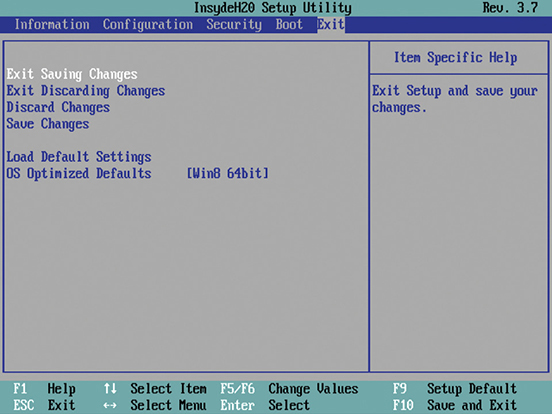
• Figure 5.31 Exit options
 Tech Tip
UEFI Presets/Profiles
People serious about tweaking UEFI settings for maximum performance (overclocking) or minimum energy use (underclocking) can use a feature in some system setup utilities to save customized settings. Various utilities call them presets or profiles—essentially it’s a “save these settings as” option. If something isn’t quite right with the changes, go back into setup, make some changes, and try again. If you’re done fiddling for the day and want to play with a stable machine, pick the profile you created that is the stable machine. See “Care and Feeding of BIOS/UEFI” later in this chapter for the ultimate undo features.
The CMOS setup utility would meet all the needs of a modern system for BIOS if manufacturers would just stop creating new devices. That’s not going to happen, of course, so let’s turn now to devices that need to have BIOS loaded from elsewhere.
■ Power-On Self-Test (POST)
BIOS isn’t the only program on system ROM. When the computer is turned on or reset, it initiates a special program called the power-on self-test (POST). The POST program checks out the system every time the computer boots. To perform this check, the POST sends out a command that says to all of the devices, “Check yourselves out!” All of the standard devices in the computer then run their own built-in diagnostic—the POST doesn’t specify what they must check. The quality of the diagnostic is up to the people who made that particular device.
Let’s consider the POST for a moment. Suppose some device—let’s say it’s the keyboard controller chip—runs its diagnostic and determines that it is not working properly. What can the POST do about it? Only one thing really: tell the human in front of the PC! So how does the computer tell the human? PCs convey POST information to you in two ways: beep codes and text messages.
Before and During the Video Test: The Beep Codes
The computer tests the most basic parts of the computer first, up to and including the video card. In early PCs, you’d hear a series of beeps—called beep codes or POST beeps—if anything went wrong. By using beeps before and during the video test, the computer could communicate with you. (If a POST error occurs before the video is available, obviously the error must manifest itself as beeps, because nothing can display on the screen.) The meaning of the beep code you’d hear varied among different BIOS manufacturers. You could find the beep codes for a specific motherboard in its motherboard manual.
Most modern PCs have only two beep codes: one for bad or missing video (one long beep followed by two or three short beeps), and one for bad or missing RAM (a single beep that repeats indefinitely).
![]()
You’ll hear three other beep sequences on most PCs (although they’re not officially beep codes). At the end of a successful POST, the PC produces one or two short beeps, simply to inform you that all is well. Most systems make a rather strange noise when the RAM is missing or very seriously damaged. Unlike traditional beep codes, this code repeats until you shut off the system. Finally, your speaker might make beeps for reasons that aren’t POST or boot related. One of the more common is a series of short beeps after the system’s been running for a while. That’s a CPU alarm telling you the CPU is approaching its high heat limit.
Text Errors
After the video has tested okay, any POST errors display on the screen as text errors. If you get a text error, the problem is usually, but not always, self-explanatory (see Figure 5.32). Text errors are far more useful than beep codes, because you can simply read the screen to determine the bad device.

• Figure 5.32 POST text error messages
POST Cards
Beep codes, numeric codes, and text error codes, although helpful, can sometimes be misleading. Worse than that, an inoperative device can sometimes disrupt the POST, forcing the machine into an endless loop. This causes the PC to act dead—no beeps and nothing on the screen. In this case, you need a device, called a POST card, to monitor the POST and identify which piece of hardware is causing the trouble.
POST cards are simple cards that snap into expansion slots on your system. A small, two-character LED readout on the card indicates which device the POST is currently testing (see Figure 5.33).

• Figure 5.33 POST card in action
POST cards used to be essential tools for techs, but today I use them only when I have a “dead” PC to determine at which level it’s dead. If the POST card shows no reading, I know the problem is before the POST and must be related to the power, the CPU, the RAM, or the motherboard. If the board posts, then I know to look at more issues, such as the drives and so on.
The Boot Process
All PCs need a process to begin their operations. Once you feed power to the PC, the tight interrelation of hardware, firmware, and software enables the PC to start itself, to “pull itself up by the bootstraps” or boot itself.
When you first power on the PC, the power supply circuitry tests for proper voltage and then sends a signal down a special wire called the power good wire to awaken the CPU. The moment the power good wire wakes it up, every Intel and clone CPU immediately sends a built-in memory address via its address bus. This special address is the same on every Intel and clone CPU, from the oldest 8086 to the most recent microprocessor. This address is the first line of the POST program on the system ROM! That’s how the system starts the POST. After the POST has finished, there must be a way for the computer to find the programs on the hard drive to start the operating system. What happens next differs between the old BIOS way and the UEFI way.
In the older BIOS environment, the POST passes control to the last BIOS function: the bootstrap loader. The bootstrap loader is little more than a few dozen lines of BIOS code tacked to the end of the POST program. Its job is to find the operating system. The bootstrap loader reads CMOS information to tell it where to look first for an operating system. Your PC’s system setup utility has an option that you configure to tell the bootstrap loader which devices to check for an operating system and in which order—that’s the boot sequence (see Figure 5.34).
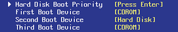
• Figure 5.34 System Setup boot sequence
Almost all storage devices—hard disk drives, solid-state drives, optical drives, and USB thumb drives—can be configured to boot an operating system by setting aside a specific location called the boot sector. If the device is bootable, its boot sector contains special programming designed to tell the system where to locate the operating system. Any device with a functional operating system is called a bootable disk or a system disk. If the bootstrap loader locates a good boot sector, it passes control to the operating system and removes itself from memory. If it doesn’t, it goes to the next device in the boot sequence you set in the CMOS setup utility. The boot sequence is an important tool for techs because you can set it to load in special bootable devices so you can run utilities to maintain PCs without using the primary operating system.
In UEFI systems, the POST hands control of the boot process to the Boot Manager, which checks the boot configuration, and then loads the operating system boot loader directly (see Figure 5.35). There’s no need for scanning for a boot sector or any of that. UEFI firmware stores the Boot Manager and boot configuration.

• Figure 5.35 UEFI boot mode with Boot Manager options displayed
Some BIOS include a feature that enables a PC to use a preboot execution environment (PXE). A PXE enables you to boot a PC without any local storage by retrieving an OS from a server over a network. You’ll see more on PXE when we talk about installing Windows in Chapter 11.
■ Care and Feeding of BIOS/UEFI
BIOS/UEFI and system setup are areas in your PC that you don’t go to very often. BIOS/UEFI itself is invisible. The only real clue you have that it even exists is the POST. The system setup utility, on the other hand, is very visible if you start it. While system setup utilities today work acceptably well without ever being touched, you’re an aspiring tech, and all self-respecting techs start up the system setup utility and make changes. That’s when most system setup utility problems take place.
This section shows you how to navigate a system setup utility and change settings. Keep in mind that you should make only as many changes at one time as you can remember. Document the original settings and the changes on a piece of paper or take a photo so that you can restore the original settings if necessary. Don’t make changes unless you know what they mean! It’s easy to screw up a computer fairly seriously by playing with CMOS settings you don’t understand.
Default/Optimized Settings
Every system setup utility has a couple of reset options, commonly called Load Default Settings and OS Optimized Defaults (see Figure 5.36). These options keep you from having to memorize all of those weird settings you’ll never touch. Default or Fail-Safe sets everything to very simple settings—you might occasionally use this setting when very low-level problems such as freeze-ups occur and you’ve checked more obvious areas first. Optimized sets the system to the best possible speed/stability for the system. You would use this option after you’ve tampered with the system setup too much and need to put it back like it was!
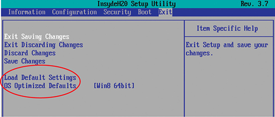
• Figure 5.36 Options for resetting CMOS
Clearing CMOS
You read about the process for clearing system settings back in Chapter 3, but the process is worth repeating here. When you mess up a setting (by overclocking too much or disabling something that should have remained enabled—or vice versa) that renders the computer dead, you can reset the CMOS back to factory defaults and start over.
Almost every motherboard has a dedicated set of wires called CLRTC or something similar (see Figure 5.37).

• Figure 5.37 CMOS RTC clear wires
Turn off and unplug the computer, then open the case to access the motherboard. Find the CMOS RTC clear wires. Move the shunt (the little plastic and metal jumper thing) from wires 1 and 2 to wires 2 and 3 (see Figure 5.38). Wait for 10 seconds and then move the shunt back to the default position. Plug in and boot the system.
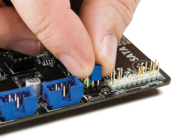
• Figure 5.38 Changing shunt location to clear CMOS RAM
If that doesn’t work or if you get one of the truly odd motherboards without CLRTC jumpers, power down the system and unplug. Pry out the little coin battery (described next) and wait for several seconds. Reinstall and reboot.
Losing CMOS RTC Settings
As mentioned before, your CMOS RAM needs a continuous trickle charge to keep the internal clock running and remember its settings. Motherboards use some type of battery, usually a 3-volt Lithium-Ion coin battery, to give the CMOS RAM the charge it needs when the computer is turned off (see Figure 5.39). This is called the CMOS battery. Typical systems use a CR2032 battery. (What does your system use?)

• Figure 5.39 A CMOS battery
If some mishap suddenly erases the information on the CMOS RAM, the computer might not boot or you’ll get nasty-looking errors at boot. Any PC will boot to factory defaults if the CMOS clears, so the chances of not booting are slim—but you’ll still get errors at boot. Here are a few examples of errors that point to a lost CMOS information scenario:
■ CMOS configuration mismatch
■ CMOS date/time not set
■ BIOS time and settings reset
■ No boot device available
■ CMOS battery state low
Here are some of the more common reasons for losing CMOS data:
■ Pulling and inserting cards
■ Touching the motherboard
■ Dropping something on the motherboard
■ Dirt on the motherboard
■ Faulty power supplies
■ Electrical surges
If you run into any of these scenarios, or if the clock in Windows resets itself to January 1st every time you reboot the system, the battery on the motherboard is losing its charge and needs to be replaced. To replace the battery, use a screwdriver to pry the battery’s catch gently back. The battery should pop up for easy removal. Before you install the new battery, double-check that it has the same voltage and amperage as the old battery. To retain your CMOS settings while replacing the battery, simply leave your PC plugged into an AC outlet. The 5-volt soft power on all modern motherboards provides enough electricity to keep the CMOS charged and the data secure. Of course, I know you’re going to be extremely careful about ESD while prying up the battery from a live system!
Flashing the ROM
Flash ROM chips can be reprogrammed to update their contents. With flash ROM, when you need to update your system BIOS to add support for a new technology, you can simply run a small command-line program, combined with an update file, and voilà, you have a new, updated BIOS! This is called a firmware update. Different BIOS makers use slightly different processes for flashing the BIOS, but, in general, you insert a removable disk of some sort (usually a USB thumb drive) containing an updated BIOS file and use the updating utility in system setup.
![]()
Some motherboard makers provide Windows-based flash ROM update utilities that check the Internet for updates and download them for you to install. Most of these utilities also enable you to back up your current BIOS so you can return to it if the updated version causes trouble. Without a good backup, you could end up throwing away your motherboard if a flash BIOS update goes wrong, so you should always make one.
Finally, a lot of motherboards these days have system setup utilities that can connect directly to the Internet and access updates that way. Figure 5.40 shows one such update utility.

• Figure 5.40 ROM-updating program for an ASUS motherboard
Just a word of caution to complete the BIOS update section. Don’t update your BIOS unless you have some compelling reason to do so. Some common reasons are supporting larger drive capacities, supporting faster RAM speeds, and security enhancements. As the old saying goes, “If it ain’t broke, don’t fix it!”
Tech Tip
Flashing the BIOS
While techs usually talk about “flashing the BIOS,” CompTIA refers to this process also as “firmware updates.”
Chapter 5 Review
■ Chapter Summary
After reading this chapter and completing the exercises, you should understand the following about firmware.
Define and explain the function of firmware, UEFI, BIOS, CMOS, ROM
■ The CPU must be able to communicate with all devices in a computer system. In a classic system, the northbridge chip was the primary communication bridge between the CPU and the rest of the computer. The northbridge dealt with high-speed devices such as the video card, RAM, and the expansion bus. A second chip, the southbridge, worked with the other devices. The northbridge and southbridge chips worked as a set called the chipset. The chipset extended the data and address buses to every device in the PC.
■ Modern processors include most of the functions of the chipset directly on the CPU. The few remaining controls are handled by an updated southbridge called the Platform Controller Hub (PCH) for Intel systems, and just the chipset for AMD systems.
■ The CPU doesn’t magically or otherwise automatically know how to talk with any controller; it needs some sort of programming—a codebook of commands, ready to go in memory, to speak to that particular controller. We call this codebook a device driver
■ A ROM (read-only memory) chip is nonvolatile, meaning it retains the information stored on it even when the power is turned off. The ROM chip stores hundreds of little programs that enable the CPU to communicate with basic devices such as optical drives, hard drives, video cards, and others. These programs, called services, are collectively referred to as the basic input/output services (BIOS). These programs are stored on a read-only medium and can’t be changed by the user, so they are known as firmware, in contrast to software, which are programs stored on erasable media. The term “system ROM” refers to the ROM chip on the motherboard.
■ Modern systems use firmware programming called the Unified Extensible Firmware Interface (UEFI). UEFI is a programming standard that defines how we configure utilities that every system needs: device drivers, boot support, and system setup—all on the motherboard’s flash ROM chip. UEFI essentially provides the programming that enables the CPU to communicate with other hardware.
Distinguish among various system setup utility options
■ Motherboards include a small memory chip, capable of storing about 64 KB of data, called the CMOS chip. CMOS does not store programs. It stores the data that is read by BIOS, and that data is used by the programs residing in BIOS. The CMOS chip also keeps track of the date and time. To maintain its date, CMOS requires a constant trickle of electricity supplied by a small battery on the motherboard. If the data you have stored in CMOS continues to disappear or if the date/time resets itself, it may be time to change the CMOS battery.
■ Within the system ROM is a system setup program that lets you access and update the data on the CMOS chip. The terms CMOS setup program, CMOS, and system setup utility are functionally interchangeable today. Most techs just call it the CMOS.
■ The system setup program can be started in many different ways, depending on the brand of BIOS you have on your computer. Typically, pressing DELETE when the computer boots is the most common way to access the CMOS setup program. The screen itself usually tells you how to access setup. If it doesn’t, you can check the motherboard book or the Web site of your PC or BIOS manufacturer.
■ All CMOS setup programs have basically the same main options. This is true of both graphical and text-based setup programs. One screen will have information about core system components, such as type of CPU and RAM. Often this screen enables you to change the date/time settings. Other screens enable you to control such items as memory management, password and booting options, diagnostic and error handling, and power management.
■ Among the other things you can configure in system setup are the voltage and multiplier settings for the CPU, boot options such as the boot sequence, and security features such as Secure Boot. Other security-related options include TPM. All setup programs include options to Save and Exit or Exit Without Saving, though the wording on these options varies. You should not change CMOS settings unless you know exactly what you’re doing.
Troubleshoot using the power-on self-test (POST)
■ In addition to the BIOS routines and the CMOS setup program, the system ROM also includes a special program called the power-on self-test (POST) that is executed every time the computer boots. POST first sends a command to basic devices, up to and including video, instructing them to run self-diagnostics. If a device detects an error, the computer alerts you with a series of beeps.
■ Different ROM manufacturers have used different beep codes, but your motherboard book should explain them (particularly in older systems). After addressing the basic devices, POST tells the rest of the devices to run tests and displays a text error message on the screen if anything is wrong. Some manufacturers use numeric error codes or combine numeric and text messages.
■ The computer may beep in two situations that are not related to POST beep codes. If the computer beeps constantly until you shut it off, it means RAM is missing or damaged. If the computer beeps after it is booted, it is probably warning you that the system is overheating.
■ If the computer appears dead, with no beeps or screen response, you can place a POST card in an expansion slot to diagnose the problem by using the LED readout on the card. The documentation that comes with the POST card explains the LED codes for your particular BIOS.
■ A beep code, text error message, or POST error may identify a problem, but it does not fix it. After you know which device is causing the problem, you should check the connection for the troublesome device and replace it if possible. If you cannot remove the bad part or if you cannot interpret the error message, you may need to replace the motherboard.
■ When you first power on the PC, the power supply circuitry tests for proper voltage and then sends a signal down a special wire called the power good wire to awaken the CPU. The moment the power good wire wakes it up, the CPU sends a built-in memory address via its address bus. This address is the first line of the POST program on the system ROM, which is how the system starts the POST.
■ In UEFI systems, the POST hands control of the boot process to the boot manager, which checks the boot configuration and then loads the operating system boot loader directly.
■ Some BIOS include a feature enabling your PC to use a preboot execution environment (PXE). A PXE enables you to boot your PC from a network location.
Maintain BIOS/UEFI settings
■ If you make changes to the CMOS settings, make only as many changes at one time as you can remember. Document the original settings and the changes on a piece of paper or take a photo so you can reverse any changes that have the wrong effect.
■ To reset CMOS settings back to their default, power off and unplug the system. Move the shunt to the clear position on the CLRTC wires. Wait. Then put the shunt back in the default position. Or, locate the flat, round CR2032 Li-Ion battery on the motherboard and carefully remove it. Wait five minutes and then reseat it. Power on the system.
■ If you have CMOS settings that keep reverting to defaults or if the clock in Windows resets itself to January 1st every time you reboot the system, the battery on the motherboard is losing its charge and needs to be replaced.
■ You can update the firmware in ROM by flashing the BIOS. Some motherboards enable you to update the BIOS through Windows programs; others come with drivers for USB devices and have a flashing utility built in.
■ Key Terms
administrator password
basic input/output services (BIOS)
BIOS/UEFI password
beep code
boot option
chipset
CLRTC
CMOS battery
complementary metal-oxide semiconductor (CMOS)
device driver
firmware
firmware update
flash ROM
hardware-assisted virtualization
nonvolatile
Platform Controller Hub (PCH)
POST card
power good
power-on self-test (POST)
preboot execution environment (PXE)
read-only memory (ROM)
Secure Boot
service
system ROM
system setup utility
Trusted Platform Module (TPM)
Unified Extensible Firmware Interface (UEFI)
user password
■ Key Term Quiz
Use the Key Terms list to complete the sentences that follow. Not all terms will be used.
1. Loaded when the operating system boots, a(n) __________________ is a file that contains instructions to support a hardware device.
2. If the computer appears dead, with no beeps or screen responses, you can insert a(n) __________________ in an expansion slot to diagnose what is wrong.
3. You can update the __________________ chip.
4. Unlike RAM, which loses all data when the computer is shut down, a ROM chip is __________________, retaining the information even when the power is off.
5. The hundreds of programs in the system ROM chip are collectively called the __________________.
6. A(n) __________________ enables a PC to boot to an OS stored on a server over a network.
7. The tiny bit of writeable memory the UEFI needs to keep it working when the PC is off and unplugged is called the __________________.
8. ___________ requires that every piece of firmware and software, including the operating system, be digitally signed.
9. Windows BitLocker Drive Encryption requires a(n) _________ chip to encrypt drives.
10. If POST detects an error before the video is tested, it uses a(n) __________ to inform the user.
■ Multiple-Choice Quiz
1. A new user to your IT department’s high-security area calls first thing Monday morning saying her system doesn’t recognize her USB thumb drive. She’s looked at the computer, but it seems normal. What does this tell you about her computer?
A. Her computer has TPM enabled in the CMOS.
B. Her computer has fan monitoring enabled in CMOS and the fan stopped over the weekend.
C. Her USB permissions have been turned off in the system setup.
D. It doesn’t tell you anything about the computer, only that the user has a problem.
2. To which of the following can a PC boot?
A. Hard drive
B. Optical media
C. USB drive
D. All of the above
3. The Secure Boot standard requires all code to be ________?
A. OEM compliant
B. Digitally signed
C. Universal firmware
D. Flash ROM
4. What does BIOS provide for the computer? (Choose the best answer.)
A. The physical interface for various devices such as USB and Thunderbolt ports
B. The programming that enables the CPU to communicate with other hardware
C. Memory space for applications to load into from the hard drive
D. Memory space for applications to load into from the main system RAM
5. Which of the following will most likely result in a POST beep code message?
A. The system is overheating.
B. The video card is not seated properly.
C. The keyboard is unplugged.
D. The hard drive has crashed.
6. Which of the following statements is true about system setup?
A. System setup is a configuration program that runs from the hard drive during booting.
B. System setup is a low-energy utility that draws power from a battery while the computer is turned off.
C. System setup includes the power-on self-test (POST) routines.
D. System setup is stored in the southbridge chip that controls input and output devices.
7. Which of the following is configured in system setup?
A. Boot options
B. Disk formatting
C. Desktop settings
D. Windows password
8. Which of the following most typically enables you to update a flash ROM chip?
A. Remove the chip and replace it with a different one.
B. Reboot the computer into upgrade mode.
C. Install a different operating system.
D. Plug in a USB drive containing a new BIOS file and run the updating utility in the system setup.
9. After a sudden power outage, Morgan’s PC rebooted, but nothing appeared on the screen. The PC just beeps at him, over and over and over. What’s most likely the problem?
A. The power outage toasted his RAM.
B. The power outage toasted his video card.
C. The power outage toasted his hard drive.
D. The power outage toasted his CPU.
10. Mohinder finds that a disgruntled former employee decided to sabotage his computer when he left by putting a password in CMOS that stops the computer from booting. What can Mohinder do to solve this problem?
A. Mohinder should boot the computer while holding the left SHIFT key. This will clear the CMOS information.
B. Mohinder should try various combinations of the former employee’s name. The vast majority of people use their name or initials for CMOS passwords.
C. Mohinder should find the CLRTC jumper on the motherboard. He can move the shunt on the jumper to clear the CMOS information.
D. Mohinder should find a replacement motherboard. Unless he knows the CMOS password, there’s nothing he can do.
11. In classic systems, which chip, now replaced by the CPU itself, did the CPU use to communicate with high-speed devices such as video cards or RAM?
A. Complementary metal-oxide semiconductor
B. Northbridge
C. Southbridge
D. Scan code
12. When your computer boots and you press the appropriate key to enter the system setup utility, a small program loads, allowing you to specify settings for various hardware devices. Where is this small program permanently stored?
A. In the ROM
B. In CMOS
C. On the hard drive
D. In RAM
13. When you enter the system setup utility (as in the previous question) and make changes, where are your settings stored?
A. In the BIOS
B. In CMOS
C. On the hard drive
D. In RAM
■ Essay Quiz
1. You’ve been hired as a tutor for Tom, a fellow student in your hardware class. He’s having a difficult time understanding the role that the BIOS/UEFI plays in booting the computer. How will you explain this process to him? Be sure to explain in order the step-by-step process that the BIOS/UEFI goes through from the time you turn on the computer until it relinquishes control to the operating system.
2. Why do some POST error messages manifest themselves as beep codes while others display as text messages? What should you do if you get a POST error message?
3. What symptoms will your computer show if the CMOS battery is dying or dead? What happens to the information stored in CMOS when you replace the battery? What must you do if a built-in battery goes dead?
Lab Projects
• Lab Project 5.1
Use the motherboard book (if you have one or can download one) or check the Web site of your BIOS/UEFI manufacturer to identify what each of the following POST error messages means:
■ A numeric message of 301
■ One long beep followed by three short beeps
■ A numeric message of 601
■ HDD controller failure
• Lab Project 5.2
Watch closely as your computer boots to see if it displays a message about how to reach the setup program. If it does not, consult your motherboard book to try to locate this information. Then, using the method appropriate for your system BIOS, access the setup program and examine the various screens. Do not change anything! Usually, your motherboard book includes default settings for the various setup screens and perhaps includes explanations of the various choices. Compare what you see on the screen with what the book says. Do you see any differences? If so, how do you account for these differences? As you examine the setup program, answer the following questions:
1. How do you navigate from one screen to the next? Are there menus across the top or do you simply jump from one page of options to the next? Are there instructions on the screen for navigating the setup program?
2. What is the boot sequence for your computer? In other words, in what order does the BIOS look for a bootable device?
3. What is the core voltage of the CPU?
4. How many SATA or SSD drives does the BIOS list?
When you have finished, pick the interface option that allows you to exit without saving changes.