chapter 8
Mass Storage Technologies
“Any sufficiently advanced technology is indistinguishable from magic.”
—ARTHUR C. CLARKE

In this chapter, you will learn how to
■ Explain how hard drives work
■ Identify mass storage interface connections
■ Describe how to protect data with RAID
■ Describe hard drive installation
Of all the hardware on a PC, none gets more attention—or gives more anguish—than mass storage drives. There’s a good reason for this: if a drive breaks, you lose data. As you probably know, when data goes, you have to redo work, restore from a backup, or worse, just kiss the data goodbye. It’s good to worry about data, because that data runs the office, maintains the payrolls, and stores the e-mail.
This chapter focuses on how drives work, beginning with the internal layout and organization of drives. You’ll look at the different types of drives used today and how they interface with the PC. The chapter covers how more than one drive may work with other drives to provide data safety and improve speed through a feature called RAID. The chapter wraps up with an extensive discussion on how to install drives properly into a system. Let’s get started.
Historical/Conceptual
■ How Hard Drives Work
Hard drives come in two major types. First are hard disk drives (HDDs) that store data on spinning platters, with moving read/write heads. Second are the more recent solid-state drives (SSDs), which are faster, contain no moving parts, and have become the predominant form of mass storage for most systems. Let’s look at both types of hard drives.

Hard Drives
A traditional hard disk drive (HDD) is composed of individual disks, or platters, with read/write heads on actuator arms controlled by a servo motor—all contained in a sealed case that prevents contamination by outside air (see Figure 8.1).

• Figure 8.1 An enclosed HDD (top) and an opened HDD (bottom)
The aluminum platters are coated with a magnetic medium. Two tiny read/write heads service each platter, one to read/write on top of the platter and the other to read/write on the bottom of the platter (see Figure 8.2). Each head has a bit-sized transducer to read or write to each spot on the drive. Many folks refer to traditional HDDs as magnetic hard drives, spinning drives, spindles, mechanical drives, or sometimes spinning rust.

• Figure 8.2 Read/write heads on actuator arms
1101
Spindle (or Rotational) Speed
Hard drives rotate at a set spindle speed, with the spinning platters measured in revolutions per minute (RPM). The faster the spindle speed, the faster the drive stores and retrieves data. By far the two most common speeds are 5400 RPM and 7200 RPM. Higher performance drives (which are also far less common) run at 10,000 and 15,000 RPM.
Faster drives generally equate to better performance, but they also generate more noise and heat. Excess heat cuts the life of hard drives dramatically. A rise of 5 degrees (Celsius) may reduce the life expectancy of a hard drive by as much as two years. Airflow through a system’s case makes or breaks your system stability, especially when you add new drives that increase the ambient temperature. Hot systems get flaky and lock up at odd moments. Many things can impede the airflow—jumbled-up ribbon cables (used by older storage systems, USB headers, and other attachments), drives squished together in a tiny case, fans clogged by dust or animal hair, and so on. Fewer and fewer systems these days even have any traditional hard drives, so many modern cases tuck the drive bays away at the bottom-front (see Figure 8.3), sometimes under a PSU shroud that keeps the drives and power supply out of sight. This prevents the drives from obstructing airflow to more heat-sensitive components. An optional intake fan at the bottom-front of the case can help cool the drives themselves.

• Figure 8.3 Hard drive bays in a modern case layout
Technicians need to consider airflow when adding a new hard drive to an older system. Get into the habit of tying off non-aerodynamic cables, adding front fans to cases when systems lock up intermittently, and making sure any fans run well. Finally, if a client wants a new drive for a system in a tiny minitower with only the power supply fan to cool it off, be gentle, but definitely steer the client to one of the lower RPM or SATA SSD drives discussed later in this chapter.
Form Factors
Hard disk drives are manufactured in two standardized form factors, 2.5-inch and 3.5-inch (see Figure 8.4). You’ll see both form factors in desktops and servers; most laptops use the 2.5-inch form factor.

• Figure 8.4 2.5-inch drive stacked on top of a 3.5-inch drive
The form factor only defines size. The connections and the storage technology inside these drives can vary.
Solid-State Drives
Booting up a computer takes time in part because a traditional hard drive needs to spin up before the read/write heads can retrieve data off the drive and load it into RAM. All of the moving metal parts of a platter-based hard drive use a lot of power, create a lot of heat, take up space, wear down over time, and take a lot of nanoseconds to get things done. A solid-state drive (SSD) addresses these issues nicely.
In technical terms, solid-state technology and devices are based on the combination of semiconductors and transistors used to create electrical components with no moving parts. That’s a mouthful! In simple terms, SSDs use flash memory chips to store data instead of all those pesky metal spinning parts used in platter-based hard drives (see Figure 8.5).

• Figure 8.5 A solid-state drive
Solid-state drives are everywhere today. Desktops and laptops use SSDs, and smartphones, USB thumb drives, and other handheld devices all use SSD in some form for mass storage.
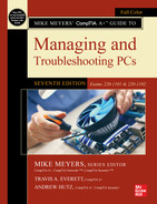
SSDs for personal computers come in one of three form factors: the 2.5-inch form factor previously mentioned and two flat form factors called mSATA and M.2 (see Figure 8.6). mSATA and M.2 drives connect to specific mSATA or M.2 slots on motherboards (see Figure 8.7). Many current motherboards offer two or more M.2 slots.
• Figure 8.6 M.2 SSD

• Figure 8.7 M.2 SSD installed in motherboard

M.2 slots come in a variety of configurations, keyed for different sorts of mass storage uses. The keys have a letter associated. M.2 slots that use Key B, Key M, or Keys B+M support mass storage devices, for example, like in Figure 8.7. Other slots like Key A and Key E are used in wireless networking devices. The specifics of the keys are beyond the current CompTIA A+ exam, but M.2 looks like it’s here to stay, so you need to be aware of the variations.
M.2 SSDs come in a few different sizes to allow them to be used in a variety of systems and circumstances. They are designated with a four-digit (or occasionally five-digit) number. The first two digits indicate the width in millimeters, and the remaining digits represent the length. An M.2 SATA drive or NVMe drive (introduced later in the chapter) with the designation 2280 would therefore be 22 mm wide by 80 mm long. The most common dimensions for M.2 SSDs are 2242, 2260, 2280, and 22110 (see Figure 8.8 for a size comparison). Longer drives are able to accommodate more flash memory chips and, therefore, have greater potential storage capacity.

• Figure 8.8 M.2 SSD size comparison in relation to a standard ATX motherboard
SSDs use nonvolatile flash memory such as NAND that retains data when power is turned off or disconnected. (See Chapter 10 for the scoop on flash memory technology.)
Cost
SSDs cost more than HDDs. Less expensive SSDs typically implement less reliable multi-level cell (MLC) memory technology in place of the more efficient single-level cell (SLC) technology to cut costs. The most popular type of memory technology in SSDs is 3D NAND, a form of MLC that stacks cells vertically, providing increased density and capacity.
Solid-state drives operate internally by writing data in a scattershot fashion to high-speed flash memory cells in accordance with the rules contained in the internal SSD controller. That process is hidden from the operating system by presenting an electronic façade to the OS that makes the SSD appear to be a traditional magnetic hard drive.
Performance Variables
There are three big performance metrics to weigh when you buy an SSD: how fast it can read or write long sequences of data stored in the same part of the drive, how fast it can read or write small chunks of data scattered randomly around the drive, and how quickly it responds to a single request. The value of each metric varies depending on what kind of work the drive will do. Before we dive into how you should weigh each metric, let’s look at how the storage industry measures the sequential read/write performance, random read/write performance, and latency of individual SSDs.
Sequential Read/Write Performance A common measure of a storage device’s top speed is its throughput, or the rates at which it can read and write long sequences of data. We usually express a device’s sequential read and sequential write throughput in megabytes per second (MBps). Most drives read a little faster than they write.
For context, traditional hard drives generally have sequential read/write speeds that top out at 200 MBps; SATA SSDs can hit 600 MBps; and NVMe SSDs roll at 2500 MBps or faster. These numbers are useful if you know your drives will frequently read and write huge files, but very few real-world systems do.
Random Read/Write Performance Because real-world drives rarely get to read and write huge files all day, we also look at a drive’s random read, random write, and mixed random performance. Basically, we measure how many times per second a device can read or write small, fixed-size chunks of data at random locations on the drive.
The labels for these measurements often reflect the size of the data chunk (usually 4 KB), so you may see them called 4K Read, 4K Random Write, 4K Mixed, and so on. These measurements are all typically expressed as a number ofinput/output operations per second (IOPS), but you may also see them expressed in MBps. For context, traditional hard drives typically clock in at fewer than 150 IOPS, whereas the latest NVMe SSDs boast hundreds of thousands of IOPS.
Latency It’s also useful to look at a drive’s response time, access time, or latency, which measures how quickly it responds to a single request. Latency is usually expressed in milliseconds (ms) or microseconds (µs). Low-latency storage is critical for high-performance file and database servers, but the latency of most modern drives is fine for general use. For context, traditional hard drives often have latencies under 20 ms, whereas SSDs commonly clock in well under 1 ms.
 Cross Check
Latency
You ran into the concept of latency back in Chapter 4. How does latency affect performance in memory? How important is latency when comparing sticks of DDR4 or DDR5?
A lot of factors determine which combination of performance and price makes sense for a specific situation. A typical machine, for example, doesn’t put a huge demand on the SSD. Users boot up the computer and then open an application or two and work. The quality of the SSD matters for boot-up time and application load, but the machine will rarely break a sweat after that. A workstation for high-end video editing, on the other hand, may read and write massive files for hours on end. A large file server may need to read and write thousands of tiny files a minute.
In practical terms, you can get by with a cheaper, lower performing SSD in a general-use computer, but need to spend more for a higher performing SSD in demanding circumstances. When it comes to picking exactly which high-performance SSD, the throughput, IOPs, and latency metrics help you avoid overpaying for performance characteristics that don’t matter for your use.
■ Connecting Mass Storage
Setting up communication between a CPU and a mass storage drive requires two main items. First, there must be standardized physical connections between the CPU, the drive controller, and the physical drive. These connections must send data between these devices as quickly as possible while still retaining good security (see Figure 8.9).

• Figure 8.9 Standardized physical connections are essential.
Second, the CPU needs to use a standardized protocol, sort of like a special language, so it knows how to speak to the mass storage device to read and write data to the device (see Figure 8.10).

• Figure 8.10 We need a common language!
In most cases, the standards bodies that define both the physical connections and the language used for communications are the same organization. For the last 25+ years, the Storage Networking Industry Association’s Small Form Factor (SFF) committee has defined mass storage standards, the most important to CompTIA A+ techs being ATA/ATAPI.
The Advanced Technology Attachment (ATA) standards started with version 1 way back in 1990, going through ATA/ATAPI version 7. Let’s make it even easier, because only two versions of this standard have interest to techs: PATA and SATA. Parallel ATA (PATA) was introduced with ATA/ATAPI version 1. Serial ATA (SATA) was introduced with ATA/ATAPI version 7. Let’s look at both standards.
PATA
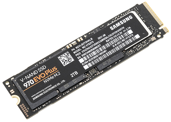
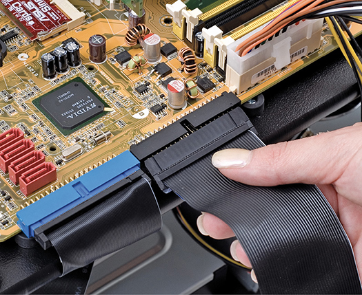
PATA drives are easily recognized by their data and power connections. PATA drives used unique 40-pin ribbon cables. These ribbon cables usually plugged directly into a system’s motherboard. Note that the exam will call these IDE cables. Figure 8.11 provides an example of a typical connection. All PATA drives used a standard Molex power connector (see Figure 8.12).
• Figure 8.11 PATA cable plugged into a motherboard
• Figure 8.12 Molex connector
As a technology standard, ATA went through seven major revisions, each adding power, speed, and/or capacity to storage system capabilities. I could add 15 pages discussing the changes, but they’re not particularly relevant for modern techs. There is one feature added back then that we still use today, though, called S.M.A.R.T.
ATA/ATAPI version 3 introduced Self-Monitoring, Analysis, and Reporting Technology (S.M.A.R.T.), an internal drive program that tracks errors and error conditions within the drive. This information is stored in nonvolatile memory on the drive and can be examined externally with S.M.A.R.T. reader software. There are generic S.M.A.R.T. reading programs, and every drive manufacturer has software to get at the vendor-specific information being tracked. Regular usage of S.M.A.R.T. software will help you create a baseline of hard drive functionality to predict potential drive failures.
SATA
For all its longevity as the mass storage interface of choice for the PC, parallel ATA had problems. First, the flat ribbon cables impeded airflow and could be a pain to insert properly. Second, the cables had a limited length, only 18 inches. Third, you couldn’t hot-swap PATA drives. You had to shut the computer down completely before installing or replacing a drive. Finally, the technology had simply reached the limits of what it could do in terms of throughput. It was time to revamp both the connection and the language for ATA/ATAPI drives.
Serial ATA addressed these issues. SATA creates a point-to-point connection between the SATA device—magnetic hard drives, solid-state drives, optical media drives—and the SATA controller, the host bus adapter (HBA). SATA drives at first glance look identical to PATA devices, but take a closer look at the cable and power connectors, and you’ll see significant differences (see Figure 8.13).
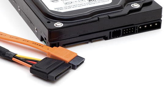
• Figure 8.13 SATA hard disk power (left) and data (right) cables
Because SATA devices send data serially instead of in parallel, the SATA interface needs far fewer physical wires—only 7 connectors instead of the 40 typical of PATA—resulting in much thinner cabling. Thinner cabling means better cable control and better airflow through the PC case, resulting in better cooling.
Further, the maximum SATA-device cable length is more than twice that of a PATA cable—about 40 inches (1 meter) instead of 18 inches. This facilitates drive installation in larger cases.
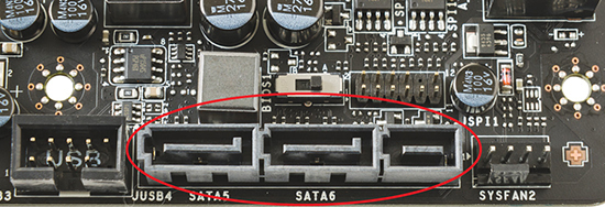
SATA did away with the two drives per cable of PATA. Each drive connects to one port. Further, there’s no maximum number of drives—many motherboards today support up to eight SATA drives (see Figure 8.14). Want more? Snap in a SATA HBA into an expansion slot and load ’em up with even more drives.

• Figure 8.14 SATA cable plugged into typical motherboard (note the other available socket)
The biggest news about SATA is in data throughput. As the name implies, SATA devices transfer data in serial bursts instead of parallel, as PATA devices do. Typically, you might not think of serial devices as being faster than parallel, but in this case, a SATA device’s single stream of data moves much faster than the multiple streams of data coming from a parallel ATA device—theoretically, up to 30 times faster. SATA drives come in three common SATA-specific varieties: 1.5 Gbps, 3 Gbps, and 6 Gbps, which have a maximum throughput of 150 MBps, 300 MBps, and 600 MBps, respectively. It should be noted that if a system has an (external) eSATA port (discussed next), it will operate at the same revision and speed as the internal SATA ports.
Traditionally you do not connect or disconnect mass storage devices to a running system. Connecting a mass storage device to a fully functioning and powered-up computer may result in less than optimal results. The result may be as simple as the component not being recognized or as dire as a destroyed component or computer.
 Tech Tip
Each SATA variety is named for the revision to the SATA specification that introduced it, with the exception of SATAe:
◾ SATA 1.0: 1.5 Gbps/150 MBps
◾ SATA 2.0: 3 Gbps/300 MBps
◾ SATA 3.0: 6 Gbps/600 MBps
◾ SATA 3.2: up to 16 Gbps/2000 MBps
Enter the era of the hot-swappable device. Hot-swapping entails two elements, the first being the capacity to plug a device into the computer without harming either. The second is that once the device is safely attached, it will be automatically recognized and become a fully functional component of the system. SATA was the first popular mass storage technology to support hot swapping.
SATA Express (SATAe) ties capable drives directly into the PCI Express bus on motherboards. SATAe drops both the SATA link and transport layers, embracing the full performance of PCIe. The lack of overhead greatly enhances the speed of SATA throughput, with each lane of PCIe 3.0 capable of handling up to 8 Gbps of data throughput. A drive grabbing two lanes, therefore, could move a whopping 16 Gbps through the bus. Without the overhead of earlier SATA versions, this translates as 2000 MBps!
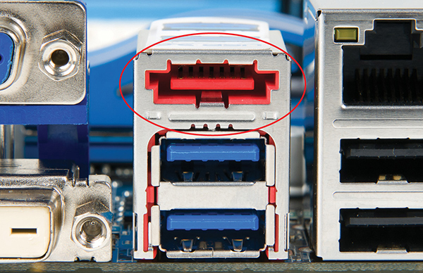
SATAe (also known as SATA 3.2) has unique connectors (see Figure 8.15) but provides full backward compatibility with earlier versions of SATA. Note that the center and left portions of the port look just like regular SATA ports. They function that way too, so you can plug two regular SATA drives into a SATAe socket. Feel free to upgrade your motherboard! Oh yeah, did I forget to mention that? You’ll need a motherboard with SATAe support to take advantage of these superfast versions of SATA drives.
• Figure 8.15 SATAe connector
eSATA and Other External Drives
External SATA (eSATA) extended the SATA bus to external devices, as the name would imply. The eSATA drives used connectors that looked similar to internal SATA connectors, but were keyed differently so you couldn’t mistake one for the other. Figure 8.16 shows an eSATA connector on the back of a motherboard.
• Figure 8.16 eSATA connector
External SATA used shielded cable in lengths up to 2 meters outside the PC and was hot-swappable. eSATA extended the SATA bus at full speed, mildly faster than the fastest USB connection when it was introduced.
Current external enclosures (the name used to describe the casing of external HDDs and SSDs) use the USB (3.0, 3.1, 3.2, or C-type) ports or Thunderbolt ports for connecting external hard drives. Chapter 10 goes into the differences among these types of ports in detail. The drives inside the enclosures are standard SATA HDDs or SSDs.
Refining Mass Storage Communication
The original ATA standard defined a very specific series of commands for the CPU to communicate with the drive controller. The current drive command sets are AHCI and NVMe.
AHCI
Current versions of Windows support the Advanced Host Controller Interface (AHCI), an efficient way to work with SATA HBAs. Using AHCI unlocks some of the advanced features of SATA, such as native command queuing and hot-swapping.
Native command queuing (NCQ) is a disk-optimization feature for SATA drives. It takes advantage of the SATA interface to achieve faster read and write speeds that are simply impossible with the old PATA drives. Also, while SATA supports hot-swapping ability, the motherboard and the operating system must also support this.
AHCI mode is enabled at the CMOS level (see “BIOS Support: Configuring CMOS and Installing Drivers” later in this chapter) and generally needs to be enabled before you install the operating system. Enabling it after installation will cause Windows to Blue Screen. How nice.
When you plug a SATA drive into a running Windows computer that does not have AHCI enabled, the drive doesn’t appear automatically. With AHCI mode enabled, the drive should appear in Computer immediately, just what you’d expect from a hot-swappable device.
Tech Tip
Successfully Switching SATA Modes Without Reinstalling
You can attempt to switch to AHCI mode in Windows without reinstalling. This scenario might occur if a client has accidentally installed Windows in Legacy/IDE mode, for example, and finds that the new SSD he purchased requires AHCI mode to perform well.
First, back up everything before attempting the switch. Second, you need to run through some steps in Windows before you change the BIOS/UEFI settings. Windows 10 and 11 use an elevated command prompt exercise with the bcdedit command. (The command line is covered in Chapter 15.)
A quick Google search for “switch from ide to ahci windows” will reveal several excellent walkthroughs of the process for Windows 10 and 11. Back everything up first!
NVMe
AHCI was designed for spinning SATA drives to optimize read performance as well as to effect hot-swappability. As a configuration setting, AHCI works for many SSDs as well, but it’s not optimal. That’s because for an SSD to work with the operating system, the SSD has to include some circuitry that the OS can see that makes the SSD appear to be a traditional spinning drive. Once a read or write operation is commenced, the virtual drive circuits pass the operation through a translator in the SSD that maps the true inner guts of the SSD.
The Non-Volatile Memory Express (NVMe) specification supports a communication connection between the operating system and the SSD directly through a PCIe bus lane, reducing latency and taking full advantage of the wicked-fast speeds of high-end SSDs (see Figure 8.17). NVMe SSDs come in a few formats, such as an add-on expansion card using a PCIe slot on the motherboard, a 2.5-inch drive that works with a SATAe connector, and the most common style, M.2 format. NVMe drives are more expensive than other SSDs but offer much higher speeds.

• Figure 8.17 NVMe enables direct-to-the-bus communication.
■ Protecting Data with RAID
Ask experienced techs “What is the most expensive part of a PC?” and they’ll all answer in the same way: “It’s the data.” You can replace any single part of your PC for a few hundred dollars at most, but if you lose critical data—well, let’s just say I know of two small companies that went out of business just because they lost a hard drive full of data.
Tech Tip
SCSI
SATA-connected HDDs and SSDs dominate the personal computer market, but another drive technology, called the small computer system interface (SCSI), rules the roost in the server market. SCSI has been around since the earliest days of HDDs and has evolved over the years from a parallel to a wider parallel to—and this should be obvious by now—a couple of super-fast serial interfaces. SCSI devices—parallel and serial—use a standard SCSI command set, meaning you can have systems with both old and new devices connected and they can communicate with no problem. SCSI drives used a variety of ribbon cables, depending on the version.
Serial Attached SCSI (SAS) hard drives provide fast and robust storage for servers and storage arrays today. The latest SAS interface, SAS-4, provides speeds of up to 22.5 Gbps. SAS controllers also support SATA drives, which is cool and offers a lot of flexibility for techs, especially in smaller server situations. SAS implementations offer more than a dozen different connector types. Most look like slightly chunkier versions of a SATA connector.
The CompTIA A+ exam objectives list SCSI as a type of hard drive cable, but surely that only means SAS. If you want to make the move to server tech, though, you’ll definitely need to know about SCSI. The SCSI Trade Association (STA) Web site provides a good starting point: https://www.scsita.org.
Data is king; data is your PC’s raison d’être. Losing data is a bad thing, so you need some method to prevent data loss. Of course, you can do backups, but if a hard drive dies, you have to shut down the computer, reinstall a new hard drive, reinstall the operating system, and then restore the backup. There’s nothing wrong with this as long as you can afford the time and cost of shutting down the system.
A better solution, though, would save your data if a hard drive died and enable you to continue working throughout the process. This is possible if you stop relying on a single hard drive and instead use two or more drives to store your data. Sounds good, but how do you do this? Well, you could install some fancy hard drive controller that reads and writes data to two hard drives simultaneously (see Figure 8.18). The data on each drive would always be identical. One drive would be the primary drive and the other drive, called the mirror drive, would not be used unless the primary drive failed. This process of reading and writing data at the same time to two drives is called disk mirroring.

• Figure 8.18 Mirrored drives
If you really want to make data safe, you can use a separate controller for each drive. With two drives, each on a separate controller, the system will continue to operate even if the primary drive’s controller stops working. This super-drive mirroring technique is called disk duplexing (see Figure 8.19). Disk duplexing is also marginally faster than disk mirroring because one controller does not write each piece of data twice.
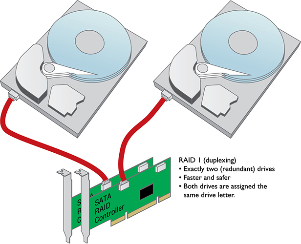
• Figure 8.19 Duplexing drives
Even though duplexing is faster than mirroring, they both are slower than the classic one-drive, one-controller setup. You can use multiple drives to increase your hard drive access speed. Disk striping (without parity) means spreading the data among multiple (at least two) drives. Disk striping by itself provides no redundancy. If you save a small Microsoft Word file, for example, the file is split into multiple pieces; half of the pieces go on one drive and half on the other (see Figure 8.20).

• Figure 8.20 Disk striping
The one and only advantage of disk striping is speed—it is a fast way to read and write to hard drives. But if either drive fails, all data is lost. You should not do disk striping—unless you’re willing to increase the risk of losing data to increase the speed at which your hard drives store and retrieve data.
Disk striping with parity, in contrast, protects data by adding extra information, called parity data, that can be used to rebuild data if one of the drives fails. Disk striping with parity requires at least three drives, but it is common to use more than three. Disk striping with parity combines the best of disk mirroring and plain disk striping. It protects data and is quite fast. The majority of network servers use a type of disk striping with parity.
RAID
A couple of sharp guys in Berkeley back in the 1980s organized many of the techniques for using multiple drives for data protection and increasing speeds as the redundant array of independent (or inexpensive) disks (RAID). An array describes two or more drives working as a unit. They outlined several forms or “levels” of RAID that have since been numbered 0 through 6 (plus a couple of special implementations). Only a few of these RAID types are in use today: 0, 1, 5, 6, 10, and 0+1.
■ RAID 0—Disk striping Disk striping requires at least two drives. It does not provide redundancy to data. If any one drive fails, all data is lost. I’ve heard this called scary RAID for that very reason.
■ RAID 1—Disk mirroring/duplexing RAID 1 arrays require at least two hard drives, although they also work with any even number of drives. RAID 1 is the ultimate in safety, but you lose storage space because the data is duplicated; you need two 2-TB drives to store 2 TB of data.
■ RAID 5—Disk striping with distributed parity Instead of dedicated data and parity drives, RAID 5 distributes data and parity information evenly across all drives. This is the fastest way to provide data redundancy. RAID 5 requires at least three drives. RAID 5 arrays effectively use one drive’s worth of space for parity. If, for example, you have three 2-TB drives, your total storage capacity is 4 TB. If you have four 2-TB drives, your total capacity is 6 TB.
■ RAID 6—Disk striping with extra parity If you lose a hard drive in a RAID 5 array, your data is at great risk until you replace the bad hard drive and rebuild the array. RAID 6 is RAID 5 with extra parity information. RAID 6 needs at least four drives, but in exchange you can lose up to two drives at the same time.
■ RAID 10—Nested, striped mirrors RAID levels have been combined to achieve multiple benefits, including speed, capacity, and reliability, but these benefits must be purchased at a cost, and that cost is efficiency. Take for instance RAID 10, also called RAID 1+0 and sometimes a “stripe of mirrors.” Requiring a minimum of four drives, a pair of drives is configured as a mirror, and then the same is done to another pair to achieve a pair of RAID 1 arrays. The arrays look like single drives to the operating system or RAID controller. So now, with two drives, we can block stripe across the two mirrored pairs (RAID 0). Cool, huh? We get the speed of striping and the reliability of mirroring at the cost of installing two bytes of storage for every byte of data saved. Need more space? Add another mirrored pair to the striped arrays!
■ RAID 0+1—Nested, mirrored stripes Like RAID 10, RAID 0+1 (or a “mirror of stripes”) is a nested set of arrays that works in opposite configuration from RAID 10. It takes a minimum of four drives to implement RAID 0+1. Start with two RAID 0 striped arrays, then mirror the two arrays to each other. Which is better: the RAID 10 or the RAID 0+1? Why not do a bit of research and decide for yourself?
Implementing RAID
RAID levels describe different methods of providing data redundancy or enhancing the speed of data throughput to and from groups of hard drives. They do not say how to implement these methods. Literally thousands of methods can be used to set up RAID. The method you use depends largely on the level of RAID you desire, the operating system you use, and the thickness of your wallet.
The obvious starting place for RAID is to connect at least two hard drives in some fashion to create a RAID array. Specialized RAID controller cards support RAID arrays of up to 15 drives—plenty to support even the most complex RAID needs. Dedicated storage boxes with built-in RAID make implementing a RAID solution simple for external storage and backups.
Once you have hard drives, the next question is whether to use hardware or software to control the array. Let’s look at both options.

Software Versus Hardware
All RAID implementations break down into either software or hardware methods. Software is often used when price takes priority over performance. Hardware is used when you need speed along with data redundancy. Software RAID does not require special controllers; you can use the regular SATA controllers to make a software RAID array. But you do need “smart” software. The most common software implementation of RAID is the built-in RAID software that comes with Windows. The Disk Management program in Windows Server versions can configure drives for RAID 0, 1, or 5, and it works with PATA or SATA (see Figure 8.21). The Storage Spaces feature in Windows 10 and 11 can do RAID 0 and 1.
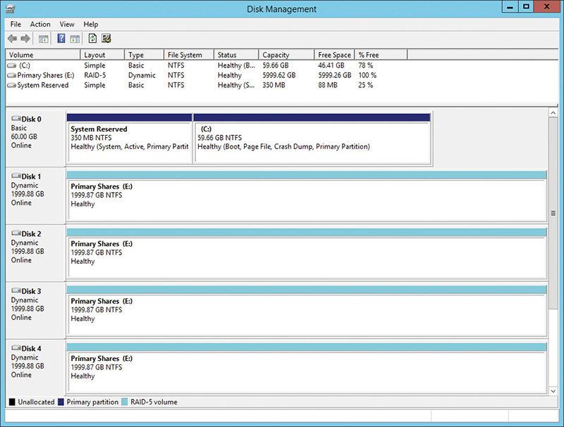
• Figure 8.21 Disk Management tool of Computer Management in Windows Server
Windows Disk Management is not the only software RAID game in town. A number of third-party software programs work with Windows or other operating systems.
Software RAID means the operating system is in charge of all RAID functions. It works for small RAID solutions but tends to overwork your operating system easily, creating slowdowns. When you really need to keep going, when you need RAID that doesn’t even let the users know a problem has occurred, hardware RAID is the answer.
Hardware RAID centers on an intelligent controller that handles all of the RAID functions (see Figure 8.22). Unlike regular PATA/SATA controllers, these controllers have chips with their own processor and memory. This allows the card or dedicated box, instead of the operating system, to handle all the work of implementing RAID.

• Figure 8.22 Serial ATA RAID controller
Most traditional RAID setups in the real world are hardware-based. Almost all of the many hardware RAID solutions provide hot-swapping—the ability to replace a bad drive without disturbing the operating system. Hot-swapping is common in hardware RAID.
Hardware-based RAID is invisible to the operating system and is configured in several ways, depending on the specific chips involved. Most RAID systems have a special configuration utility in flash ROM that you access after CMOS but before the OS loads. Figure 8.23 shows a typical firmware program used to configure a hardware RAID solution.

• Figure 8.23 RAID configuration utility
![]()
Dedicated RAID Boxes
Many people add a dedicated RAID box to add both more storage and a place to back up files. These devices take two or more drives and connect via one of the ports on a computer, such as USB or Thunderbolt (on modern systems) or FireWire or eSATA (on older systems). (See Chapter 10 for details on USB and FireWire.) Figure 8.24 shows an external RAID box (also called an enclosure). This model is typical, offering three options for the two drives inside: no RAID, RAID 0, or RAID 1.

• Figure 8.24 Western Digital RAID enclosure
■ Installing Drives
Installing a drive is a fairly simple process if you take the time to make sure you have the right drive for your system, configure the drive and system setup properly, and do a few quick tests to see if it’s running properly. Since PATA and SATA have different cabling requirements, we’ll look at each separately.
Choosing Your Drive
First, decide where you’re going to put the drive. If you have a new motherboard, just slip the drive into the M.2 socket and secure it with the tiny screw. If you plan to install a 3.5-inch HDD or 2.5-inch SSD, then you need to go old school. Look for an open SATA connection. Is it part of a dedicated RAID controller? Many motherboards with built-in RAID controllers have a CMOS setting that enables you to turn the RAID controller on or off (see Figure 8.25).

• Figure 8.25 Settings for RAID in CMOS
Second, make sure you have room for the drive in the case. Where will you place it? Do you have a spare power connector? Will the data and power cables reach the drive? A quick test fit is always a good idea.
Cabling SATA Drives
Installing SATA hard disk drives is a relatively easy and straightforward process because there are no jumper settings to worry about at all, as SATA supports only a single device per controller channel. Simply connect the power and plug in the controller cable as shown in Figure 8.26—the OS automatically detects the drive and it’s ready to go. The keying on SATA controller and power cables makes it impossible to install either incorrectly.

• Figure 8.26 Properly connected SATA cable
 Try This!
Managing Heat with Multiple Drives
Adding three or more fast magnetic hard drives into a cramped PC case can be a recipe for disaster to the unwary tech. While the heat generated may not threaten the fabric of the time-space continuum, heat reduces the life expectancy of drives and computers. You have to manage the heat inside a RAID-enabled system because such systems usually have more than the typical quantity of drives found in desktop computers. The easiest way to do this is to add fans.
Open up the PC case and look for built-in places to mount fans. How many case fans do you have installed now? What size are they? What sizes can you use? (Most cases have 120-mm and larger fans.) Jot down the fan locations of the case and take a trip to the local PC store or online retailer to check out the fans.
Before you get all fan-happy and grab the biggest and baddest fans to throw in your case, don’t forget to think about the added noise level. Try to achieve a compromise between keeping your case cool enough and avoiding early deafness.
Every modern motherboard has two or more SATA ports (or SATA connectors) built in, as shown in Chapter 6. The ports are labeled (SATA 1, SATA 2, and so forth up to however many are included). Typically, you install the primary drive into SATA 1, the next into SATA 2, and so on. With nonbooting SATA drives, such as in M.2 motherboards, it doesn’t matter which port you connect the drive to.
Connecting Solid-State Drives
SATA SSDs possess the same connectors as magnetic SATA drives, so you install an SSD as you would any SATA drive. SATA SSDs usually come in 2.5-inch laptop sizes. Just as with earlier hard drive types, you either connect SSDs correctly and they work, or you forget to plug in the power cable and they don’t.
M.2 and mSATA drives slip into their slot on the motherboard or add-on card, then either clip in place or secure with a tiny screw (see Figure 8.27). Both standards are keyed, so you can’t install them incorrectly.

• Figure 8.27 mSATA SSD secured on motherboard
Keep in mind the following considerations before implementing a HDD/SDD migration:
■ Do you have the appropriate drivers and firmware for the SSD? Newer Windows versions will load the most currently implemented SSD drivers. As always, check the manufacturer’s specifications as well.
■ Do you have everything important backed up? Good!
BIOS Support: Configuring CMOS and Installing Drivers
Every device in your PC needs BIOS support, whether it’s traditional BIOS or UEFI. Hard drive controllers are no exception. Motherboards provide support for the SATA hard drive controllers via the system BIOS, but they require configuration in CMOS for the specific hard drives attached.
In the old days, you had to fire up CMOS and manually enter hard drive information whenever you installed a new drive. Today, this process is automated.
Configuring Controllers
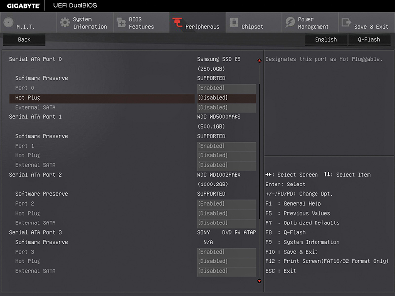
As a first step in configuring controllers, make certain they’re enabled. Most controllers remain active, ready to automatically detect new drives, but you can disable them. Scan through your CMOS settings to locate the controller on/off options (see Figure 8.28 for typical settings). This is also the time to check whether the onboard RAID controllers work in both RAID and non-RAID settings.

• Figure 8.28 Typical controller settings in CMOS
Autodetection
If the controllers are enabled and the drive is properly connected, the drive should appear in system setup through a process called autodetection. Autodetection is a powerful and handy feature that takes almost all the work out of configuring hard drives. Motherboards use a numbering system to determine how drives are listed—and every motherboard uses its own numbering system! Though not described in the figure, one common numbering method uses the term channels for each controller. The first boot device is channel 1, the second is channel 2, and so on. So instead of names of drives, you see numbers. Look at Figure 8.29.
• Figure 8.29 Standard system setup features Whew! Lots of hard drives! This mother
Whew! Lots of hard drives! This motherboard supports six SATA connections. Each connection has a number, with an M.2 SSD on SATA 0, hard drives on SATA 1 and SATA 2, and the optical drive on SATA 3. Each was autodetected and configured by the BIOS without any input from me. Oh, to live in the future!
Boot Order
If you want your computer to run, it’s going to need an operating system to boot. You assign boot order priority to drives and devices in CMOS.
Figure 8.30 shows a typical boot-order screen, with a first, second, and third boot option. Many users like to boot first from the optical drive and then from a hard drive. This enables them to put in a bootable optical disc if they’re having problems with the system. Of course, you can set it to boot first from your hard drive and then go into CMOS and change it when you need to—it’s your choice.

• Figure 8.30 Boot order
Most modern CMOS setup utilities include a second screen for determining the boot order of your hard drives. You might want to set up a boot order that starts with the optical drive, followed by the hard drive, and then the USB thumb drive, but what if you have more than one hard drive? This screen enables you to set which hard drive goes first. If you have a different operating system on each hard drive, this can be very helpful.
Enabling AHCI
On motherboards that support AHCI, you implement it in CMOS. You’ll generally have up to three options/modes/HBA configurations: IDE/SATA or compatibility mode, AHCI, or RAID. Don’t install modern operating systems in compatibility mode; it’s included with some motherboards to support ancient (Windows XP) or odd (some Linux distros, perhaps?) operating systems. AHCI works best for current HDDs and SSDs, so make sure the HBA configuration is set to AHCI.
Troubleshooting Hard Drive Installation
The best friend a tech has when it comes to troubleshooting hard drive installation is the autodetection feature of the CMOS setup utility. When a drive doesn’t work, the most obvious question, especially during installation, is “Did I plug it in correctly? Or did I plug both data and power in correctly?” With autodetection, the answer is simple: If the system doesn’t see the drive, something is wrong with the hardware configuration. Either a device has physically failed or, more likely, you didn’t give the hard drive power, plugged a cable in improperly, or messed up some other connectivity issue. To troubleshoot hard drives, simply work your way through each step to figure out what went wrong.
Make sure the BIOS recognizes the hard drive. Use the CMOS setup program to check. Check the physical connections, then run through these issues in CMOS. Is the controller enabled? Similarly, can the motherboard support the type of drive you’re installing? If not, you have a couple of options. You may be able to flash the BIOS with an upgraded BIOS from the manufacturer or get a hard drive controller that goes into an expansion slot.
Chapter 8 Review
■ Chapter Summary
After reading this chapter and completing the exercises, you should understand the following about mass storage technologies.
Explain how hard drives work
■ Traditional hard disk drives (HDDs) contain platters coated with a magnetic medium; read/write heads service each platter.
■ Magnetic hard drives run at a set spindle speed, measured in revolutions per minute (RPM). Older drives ran at a speed of 3600 RPM, and drives are sold with speeds up to 15,000 RPM. The faster the spindle speed, the faster the drive stores and retrieves data. The two most common speeds are 5400 and 7200 RPM; higher performance drives (which are far less common) run at 10,000 and 15,000 RPM.
■ Solid-state drives (SSDs) use flash memory chips to store data and don’t have any metal spinning parts. They require less electricity than platter-based hard drives and offer faster reads and writes.
■ SSDs for personal computers come in one of three form factors: the 2.5-inch form factor and two flat form factors called mSATA and M.2. mSATA and M.2 drives connect to specific mSATA or M.2 slots on motherboards.
■ You can measure the performance of SSDs in three basic areas: sustained read/write times (throughput), random read/write times (IOPS), and latency. For most workstations, any SSD will perform adequately. For specialized machines such as video editing or database workstations, you’ll want to install drives that offer the highest throughput for the former and IOPS for the latter.
Identify mass storage interface connections
■ ATA drives come in two basic flavors. The older parallel ATA (PATA) drives send data in parallel, on a wide 40-pin data cable called a ribbon cable or IDE cable. PATA drives dominated the industry for more than a decade but have been replaced by serial ATA (SATA) drives that send data in serial, using only one wire for data transfers.
■ SATA devices look identical to PATA devices (except their data and power connectors), but their thinner seven-wire data cables provide better airflow and may be up to 1 meter (38.4 inches) long. Each drive connects to one port.
■ SATA devices are hot-swappable, great for RAID technology. SATA transfers data in serial bursts and comes in several varieties, such as 1.5 Gbps, 3 Gbps, 6 Gbps, and SATA 3.2 (SATAe), which have a maximum throughput of 150 MBps, 300 MBps, 600 MBps, and 2000 MBps, respectively.
■ With eSATA, the SATA bus extends to drives plugged into eSATA ports on the external side of the case. eSATA devices run at the same speeds as internal SATA. eSATA is rare these days; the technology has been replaced by USB and Thunderbolt.
■ Magnetic SATA drives work optimally when the motherboard BIOS uses AHCI rather than earlier drive support options. SSDs function best when the BIOS implements NVMe to reduce latency, among other benefits.
Describe how to protect data with RAID
■ Drive mirroring writes data simultaneously to two hard drives, enabling the system to continue to work if one hard drive dies. A faster and even more effective technique is drive duplexing, which performs mirroring by using separate controllers for each drive. A third way to create redundant data is disk striping with parity. This technique, requiring at least three drives, combines the redundancy of disk mirroring with the speed of disk striping. Although disk striping without parity works very fast, splitting the data across two drives means you’ll lose all data if either drive fails.
■ Numbered 0 through 6, there are seven official levels of RAID, but the ones used are RAID 0 (disk striping), RAID 1 (disk mirroring or duplexing), RAID 5 (disk striping with distributed parity), and RAID 6 (disk striping with extra parity). RAID 1+0 (10) is a nested array of mirrored stripes.
■ RAID may be implemented through software or hardware methods. Although software implementation is cheaper, hardware techniques provide better performance. The most common software implementation of RAID is the built-in RAID software that comes with Windows. The Disk Management program in Windows Server versions can configure drives for RAID 0, 1, or 5, and it works with PATA or SATA. Storage Spaces in Windows 10 and 11 can do RAID 0 and 1. Hardware RAID is invisible to the OS and is usually hot-swappable. A hardware RAID controller usually requires CMOS configuration. Many motherboards include built-in hardware RAID 0 and RAID 1 capabilities.
■ You can purchase and implement dedicated RAID boxes that connect to an external port, such as USB or Thunderbolt. The boxes vary in capacity, holding two, three, four, or more drives for a variety of RAID configurations.
Describe hard drive installation
■ SATA supports only a single device per controller channel. SATA controller and power cables are keyed to prevent incorrect insertion.
■ SATA SSDs possess the same connectors as magnetic SATA drives, so you install an SSD as you would any SATA drive. SATA SSDs usually come in 2.5-inch laptop sizes. Just as with earlier hard drive types, you either connect SSDs correctly and they work, or you forget to plug in the power cable and they don’t.
■ M.2 and mSATA drives slip into their slot on the motherboard or add-on card, then either clip in place or secure with a tiny screw. Both standards are keyed, so you can’t install them incorrectly.
■ When plugging in a new hard drive to your motherboard, most BIOS can autodetect and properly configure your drive for you. You may need to enable a SATA channel in CMOS so that BIOS knows to look for a new drive, but this usually is not necessary.
■ If the autodetection feature of the CMOS utility does not detect a drive, it is installed incorrectly or the drive itself is bad. On a SATA drive, check that the SATA data and power cables are properly connected.
■ Enable AHCI to provide proper support for SATA drives and SSDs, respectively.
■ Getting a drive installed and recognized by the system takes three or four things: jumpers (PATA only), data cable, power, and CMOS setup recognizing the drive. If you miss or mess up any of these steps, you have a drive that doesn’t exist according to the PC! To troubleshoot hard drives, simply work your way through each step to figure out what went wrong.
■ Once you’ve checked the physical connections, run through these issues in CMOS. Is the controller enabled? Can the motherboard support the type of drive you’re installing? If not, you have a couple of options. You can either flash the BIOS with an upgraded BIOS from the manufacturer or get a hard drive controller that goes into an expansion slot.
■ Key Terms
1.5 Gbps
3 Gbps
6 Gbps
Advanced Host Controller Interface (AHCI)
Advanced Technology Attachment (ATA)
autodetection
channel
disk duplexing
disk mirroring
disk striping
disk striping with parity
external enclosure
external SATA (eSATA)
hard disk drive (HDD)
host bus adapter (HBA)
hot-swapping
Input/Output Operations Per Second (IOPS)
Integrated Drive Electronics (IDE)
latency
M.2
magnetic hard drive
mSATA
native command queuing (NCQ)
Non-Volatile Memory Express (NVMe)
parallel ATA (PATA)
redundant array of independent (or inexpensive) disks (RAID)
RAID 0
RAID 1
RAID 5
RAID 6
RAID 0+1
RAID 10
SATA Express (SATAe)
Self-Monitoring, Analysis, and Reporting Technology (S.M.A.R.T.)
serial ATA (SATA)
small computer system interface (SCSI)
solid-state drive (SSD)
spindle speed
throughput
■ Key Term Quiz
Use the Key Terms list to complete the sentences that follow. Not all terms will be used.
1. A traditional hard drive with spinning metal disks is known as __________________.
2. Traditional hard drives run at a set __________________, measured in RPM.
3. A(n) __________________ offers substantial performance benefits over an HDD.
4. A(n) __________________ form factor drive installs into a special slot on motherboards.
5. The older PATA drives send data in parallel; current __________________ drives send data in serial.
6. RAID 1 uses __________________ to provide redundancy and protect data from drive failures.
7. __________________ is an internal drive program that tracks errors and error conditions within a drive.
8. The __________________ specification supports a communication connection between the operating system and the SSD directly through a PCIe bus lane, reducing latency and taking full advantage of the wicked-fast speeds of high-end SSDs.
9. Seen in RAID 5, __________________ uses at least three drives and combines the best features of disk mirroring and disk striping.
10. __________________ features both nesting and striping and requires at least four drives.
■ Multiple-Choice Quiz
1. Jane replaced two 5400-RPM drives with a pair of 10,000-RPM drives, but now her system crashes under heavy use. What can she do to address this problem?
A. Add additional case fans and ensure that the drives are getting adequate airflow.
B. Enable AHCI in the CMOS setup utility.
C. Enable NCQ in the CMOS setup utility.
D. There’s nothing she can do; additional crashes are the trade-off with faster drives.
2. Which of the following SSD form factors might you expect to find in a portable device?
A. 3.5-inch
B. mSATA
C. SATAm
D. eSATA
3. Which of the following is an advantage of an NVMe SSD?
A. Lower cost
B. Higher potential storage capacity
C. Faster read/write speeds
D. The ability to hot-swap the drive
4. André wants to install the fastest SATA drive he can into his new system. The clerk at the office store threw a bunch of numbers and letters at him. Given such a scenario, which should he choose?
A. 3 Gbps
B. 6 Gbps
C. NVMe
D. SATAe
5. Jill wants to add an additional drive to her portable computer. She has a spare 1-TB SATA HDD. Given such scenario, what would enable her to accomplish her goal?
A. Put the drive into an external enclosure and plug it into a SATAe socket on the back of the portable.
B. Put the drive into an external enclosure and plug it into a USB 3.0 socket on the back of the portable.
C. Put the drive into an external enclosure and plug it into an AHCI socket on the back of the portable.
D. It can’t be done. Portable computers can only use internal drives.
6. Alex discovered a bunch of SATA drives in a box at the office and needs to check the contents. What can he do so that Windows automatically recognizes each new drive?
A. Enable AHCI in CMOS setup.
B. Enable NCQ in CMOS setup.
C. Disable HBA in CMOS setup.
D. Disable RAID in CMOS setup.
7. Of the following RAID types, which offers the best redundancy with the fewest number of drives?
A. RAID 0
B. RAID 1
C. RAID 5
D. RAID 10
8. Which level of RAID is disk striping?
A. RAID 0
B. RAID 1
C. RAID 5
D. RAID 6
9. Which of the following techniques provides redundancy by using two disks and two controllers?
A. Disk mirroring
B. Disk duplexing
C. Disk striping
D. Disk striping with parity
10. Which of the following can SSDs use to retain data integrity when a system loses power or is turned off?
A. DRAM
B. RAM drive
C. NAND
D. SDRAM
11. Jeff installs a pair of 250-GB SSDs into his computer and wants to run them in a fast RAID array to speed up his gaming experience. The motherboard SATA controller supports RAID 1, 2, and 5. When he boots his computer, however, Windows sees the drives as individual 250-GB drives. What’s up?
A. Jeff needs to install a RAID controller card. The RAID built into motherboards is always inferior.
B. Jeff needs to change the HBA configuration from AHCI to RAID.
C. Jeff needs to change the HBA configuration from AHCI to SATA.
D. Jeff needs to change the HBA configuration from SATA to AHCI.
12. Which tool in Windows enables you to implement RAID?
A. Storage Spaces
B. Disk Duplicator
C. RAID Management
D. System Tools
13. Which version of Windows enables you to set up software RAID 0+1? Select the best answer.
A. Windows 7 and later.
B. Windows 8 and later.
C. Only Windows 10.
D. Windows does not support RAID 0+1.
14. John wants to install two drives in a new system, a small SSD and a large HDD. How should he install the drives to prep the system to use the SSD for Windows and the HDD for other applications and storage?
A. He should first make sure the jumper on the SSD and HDD are on the correct setting.
B. Connect the SSD to channel 1 and the HDD to channel 2.
C. In CMOS setup, set the SSD to Boot device and the HDD to Storage device.
D. It doesn’t matter. Windows always installs on the faster drive by default.
15. Which of the following represent common solid-state drive form factors?
A. AT, ATX, and BTX
B. 8-inch, 2.5-inch, and 5.25-inch
C. 2.5-inch, M.2, and mSATA
D. IEEE 1394, USB, and SCSI
■ Essay Quiz
1. Compare and contrast software and hardware RAID implementations.
2. Your friend Blaine has a Core i5 computer with a great video card. Currently, it has only a 320-GB HDD and a DVD-RW drive. Because he’s interested in video, he knows he needs more storage capacity and wants to add a second hard drive. What advice will you give him about selecting a new hard drive?
3. Your office is about to purchase ten new portable computers for the sales force and needs a recommendation. Prepare a short essay that compares and contrasts platter-based and solid-state drives so your boss can pick what’s best for the staff.
Lab Projects
• Lab Project 8.1
Your supervisor has decided to implement RAID on the old company server machine, where everyone stores their work-related data. Come up with two competing RAID setups, one that maximizes security of data at the lowest cost possible and another that maximizes speed but retains some security. Cost is not a factor for the second RAID plan.
• Lab Project 8.2
If your lab has the equipment, install a second hard drive in your system. Reboot, enter CMOS, and verify that both drives are detected. Boot into your operating system and verify that both drives are accessible. (You may need to partition and format the second drive before it is actually usable.)