
4.8 THE SWING EQUATION
The relative position of the rotor axis and the stator magnetic field axis is fixed under normal operation. The angle between the two is known as the load angle or torque angle denoted by δ and depends upon the loading of the machine. Larger the loading, larger is the value of torque angle δ. The equation describing the relative motion of the rotor (load angle δ) with respect to the stator field as a function of time is known as the swing equation. The net torque causing acceleration is,
Ta is positive if Ts > Te for the generator
If Te > Ts the motor will accelerate. Multiplying both sides of the above equation with angular velocity ω,
and Pa = Taω = Iαω = Mα
Because torque is moment of inertia times the angular velocity. Hence ![]() Where ns is synchronous speed of the machine in rpm and a is angular acceleration in mechanical radian/sec2.
Where ns is synchronous speed of the machine in rpm and a is angular acceleration in mechanical radian/sec2.
From the above equation, M = Iω where M is in Joule-sec/mechanical radian.
No. of electrical radians or degrees = No. of mechanical radians or degrees * No. of pairs of poles, if M is expressed in Joule sec/electrical radian
When ω in mechanical radians sec, then,
M = Iω / Number of pairs of poles.
If M is to be expressed in Joule-sec/electrical degree, Then M = Iω/(Number of pairs of poles *57.32)
Hence M is known as angular momentum.
The acceleration α can be expressed in terms of the angle of the rotor as ![]() The angle θ changes continuously with respect to time and is given by
The angle θ changes continuously with respect to time and is given by
where ωr is the angular velocity of the reference the rotating axis and δ is the angular displacement in electrical degrees from the reference axis.
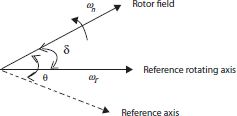
Fig 4.10 Angular position of rotor with respect to reference axis
Taking derivative of above equation
and
If we analyze the above equation in states space analysis, then,
and
writing the above equation in matrix form,
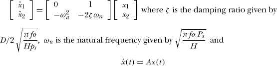
where