7.2 PROPORTIONAL PLUS INTEGRAL CONTROLLER
The block diagram of an uncontrolled single-area system with an integral controller, is shown in Fig 7.1
The integral controller gives signal to the speed changer ie ∆Pc. Hence we can write
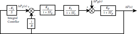
Fig 7.1 Block diagram of a proportional plus integral controller
The negative sign indicates that for a positive frequency error, the speed changer signal should be decreased and vice versa.
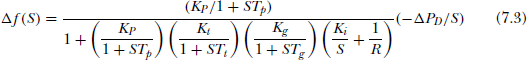
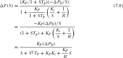
Steady State Response: For a step load increase ΔPD(S) = ΔPD / S. Therefore, from Fig 7.1
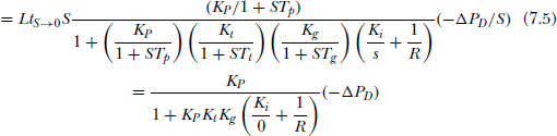
Hence from (7.7) it is clear that the presence of an integral controller makes the steady state deviation in frequency, zero.
Dynamic response:
The dynamic response for the system shown in Fig 7.1 can be derived assuming Tg = Tt = 0 and the product KgKt = 1. Hence, eqn(7.3) reduces to
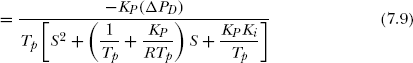
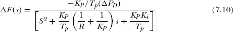
Considering the denominator of Equation(7.10)
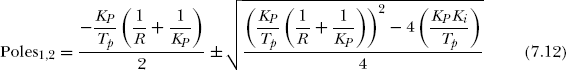
From eqn(7.11) it is evident that the nature of the poles depends on the value of Ki. Hence, considering (7.11) as characteristic equation, the poles are
Case-I:
For a critical case, the discriminant is zero.
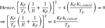
![]()
Case-II:
If Ki > Ki,critical then the roots are complex. Hence,
Thus Poles1,2 ⇒ (S + σ)2 + ω2
Δf(t) contains e−σt and e−σt whose osilations are damped in nature.
Case-III
If Ki < Ki,critical, then the roots are real, hence
Δf(t) contains the terms e−α1t and e−α2t which indicate exponential decay. In either of the above Case II and Case III, it is evident that Δf(t) will approach zero.
The dynamic response of an isolated system with integral controller is shown in Fig 7.2
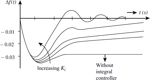
Fig 7.2 Dynamic response of an integrated system with integral controller.