8.7 METHODS TO IMPROVE POWER FACTOR
8.7.1 Synchronous Generator Control
This can be treated as the principal source of reactive power control. Synchronous machines can be made to generate or absorb reactive power depending upon their level of excitation. This control is based on the principle that an over-excited synchronous machine generates reactive power and an under-excited synchronous machine absorbs reactive power. The principal advantage of this control is that it offers flexibility for all load conditions, since it supplies reactive power when overexcited (peak load period) and consumes reactive power when it is under excited (off-peak load period). There is smooth variation in generation of reactive power by this method, when compared to the step-by-step variation by the capacitor control method.
8.7.2 Capacitor Control
Capacitors can also be treated as chief sources of reactive power available at the load end or receiving end. They are again classified into two types by the virtue of their mode of connection: (a) series capacitors and (b) shunt capacitors.
The objective of using a capacitor either in series or parallel is to compensate reactive power and to consequently improve the power factor and voltage profile of the system.
a) Series Capacitors: The series capacitors (capacitors which are connected in series with the lines) directly neutralize the inductive reactance of the system to which it is connected. Since the effect of the series capacitor can be considered as a negative reactance in series, the net impedance will be Z′ = R + j(XL – Xc). Therefore, the voltage drop IZ′ is reduced. Application of a series capacitor to a feeder and its vector diagram representation is shown in Fig. 8.7(a) and Fig. 8.7(b)
Voltage drop of the feeder without series capacitor is expressed as
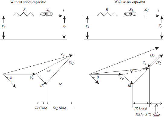
Fig 8.7 (a) Without series capacitor (b) With series capacitor
R = Resistance of the feeder
XL = Inductive reactance of the feeder
ϕ = Angle between the receiving end voltage Vr and current I in the feeder
Resultant voltage drop of the feeder with the application of series capacitor is
Where, XC = Capacitive reactance of the series capacitor
After placing a capacitor in series with a feeder, the resultant impedance will be
Therefore, IXc is the reduction in voltage drop after series compensation.
- If XL = XC then V′D = I*R i.e., the line has only resistive drop owing to the resistance of the line and zero inductive drop.
- If Cosϕ = 1 then Sinϕ = 0 and therefore, I (XL.Xc)Sinϕ = 0 and V′D = IR. In such unity power factor applications, series capacitors have practically no value.
- The power factor should be lagging if the voltage drop is to decrease considerably between the sending end and the receiving end by applying a series capacitor.
- For long transmission lines where the net reactance is high, series capacitors are effective for enhancing system stability.
b) Shunt capacitors: Shunt capacitors (capacitors connected in parallel with the lines) are widely used in distribution systems for compensating reactive power and to improve the power factor. Shunt capacitors draw a leading current which counteracts the lagging component of the inductive load current (some or the entire part) at the point of installation. Thus, it modifies the characteristics of inductive load by drawing leading current. A shunt capacitor has a similar effect as an over-excited synchronous generator or a motor. The application of a shunt capacitor to a feeder and its vector diagram representation is shown in Fig. 8.8(a) and Fig. 8.8(b)
Voltage drop of the feeder without shunt capacitor is expressed as
where,
R = Resistance of the feeder
XL = Inductive reactance of the feeder
IR = Real power component of the current (in phase)
Ix = Reactive component of current (out of phase, lagging the voltage by 90°)
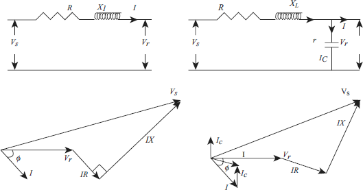
Fig 8.8 (a) Without shunt capacitor (b) With shunt capacitor
Resultant voltage drop of the feeder with the application of shunt capacitor is
Where, Ic = reactive component of the current leading the voltage by 90° (out of phase) The voltage rise due to the installation of shunt capacitor can be expressed from the difference between the above two expressions