COMPETITIVE EXAMINATION QUESTIONS
- The following data pertain to two a1tematot working in parallel and supplying a total load of 80 MW: Machine 1:40 MVA with 5% speed regulation. Machine 2:60 MVA with 5% speed regulation. The load sharing between machines 1 and 2 will be: (IES 1997)
- 30 MW
- 48 MW
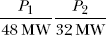
- Two generators rated at 200 MW and 400 MW are operating in parallel. Both the governors have a drop of 4%, when the total load is 300 MW They share the load as (suffix ‘1’ is used for generator 200 MW and suffix ‘2’ is used for generator 400 MW) (IES 1999)
- P1 = 100MW and P2 = 200MW
- P1 = 150MW and P2 = 150MW
- P1 = 200MW and P2 = 100MW
- P1 = 200MW and P2 = 400MW
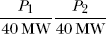
- Two alternators each having 4% speed regulation are working in parallel. Alternator ‘1’ is rated for 12 MWand alternator ‘2’ is rated for 8 MWwhen the total load is 10 MW the Loads shared by alternators 1 and 2 would be respectively. (IES 2000)
- 4 MW and 6 MW
- 6 MW and 4 MW
- 5 MW and 5 MW
- 10 MW and zero
- Two generators rated 200 MW and 400 MW having governor droop characteristics of 4% and 5% respectively are operating in parallel. If the generators operate on no load at 50 Hz, the frequency at which they would operate with a total load of 600 MW is (IES 2002)
- 48.50 Hz
- 47.69 Hz
- 46.82 Hz
- 49.04 Hz
- Consider a power system with two plants S1 and S2 connected through a tie line as shown above. When the load-frequency control of the system is considered, the ‘flat tie-line control’ system is preferred over the ‘flat frequency regulation system’, because (IES 2003)
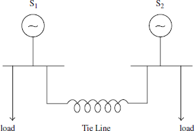
- It is advantageous to control the frequency from any one particular plant without disturbing the other one during load-swings on their S1 and S2 areas
- This ensures that only the more efficient plant’s input is controlled for load, variation in any area
- Only the tie line is required to absorb the load-swing
- The load-change in a particular area is taken care of by the generator in that area resulting in the tie-line loading to remain constant.
..................Content has been hidden....................
You can't read the all page of ebook, please click here login for view all page.