6.3 STEADY STATE ANALYSIS
6.3.1 Uncontrolled Case
Consider Fig 6.4 with
In the case when ∆Pc1 = ∆Pc2 = 0, the speed changer setting is fixed irrespective of whether the load changer is in area 1 and area 2.
Let a sudden change occur at both the areas 1 and 2. In incremental steps ∆PD1 and ∆PD2.
Due to load change the frequencies drops by ∆ƒ1 and ∆ƒ2. If load increment in the two areas is equal and if the frequency drop is also equal i.e., if ∆ƒ1 = ∆ƒ2 = ∆ƒ (ss).
From the block diagram in Fig. 6.4 the incremental increase of generation is written as
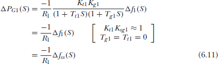
We have,
Since ∆ƒss(S) is a steady state value
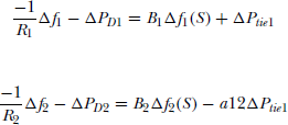
For area 1
For area 2
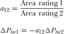
Also, we have
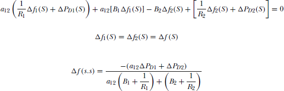
using above (6.11) and (6.12)equations(6.13) and (6.14)are written as
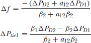
Multiplying (6.15) with α12 and subtracting it from (6.16), we will get
Similarly, from (6.15) and (6.16) ∆Ptie1 is obtained as
we have
From (6.15)
From (6.16)
Multiplying (6.17) by ![]() and (6.18) by
and (6.18) by ![]()
Subtracting (6.20) from (6.19)
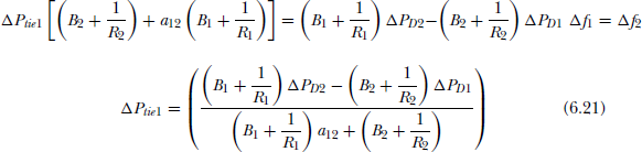
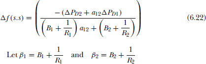
Then, Eqs. (6.21), (6.22) can be modified as
If the two areas are identical then,
Eqs. (6.21), (6.22) can be modified as
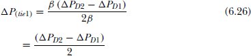
If a step load change occurs in Area 1 only, then
Therefore,
From Eqn. (6.27), it may be observed that with an interconnection and a step change in load at area 1 only, the steady state change in frequency is 50 percent of the steady state change of frequency in a single area.
Similarly from ∆Ptie1 equation (Eqn. 6.28) it is observed that if a load change occurs in any area, 50 percent is generated from Area 1.
6.3.2 Controlled Case
In the case of an isolated single-area system we used the integral control i.e., we let the speed changer command by a signal obtained by first amplifying, and then integrating the frequency error to bring the steady state deviation in frequency to zero. In the two-area system, our new control starategy should be such that both steady state frequency and tie-line deviations vanish due to change in either area. Area control error is to be defined to take care of frequency deviation and tie-line power deviation. Under normal operating conditions ∆ƒ (i.e.,) (∆ƒ1 and ∆ƒ2) and ∆Ptie1 must be zero.
But these two parameters are present under normal operating conditions. Hence these are undesirable and, as in the case of single area control, we use the PI controller to bring these two errors to zero.
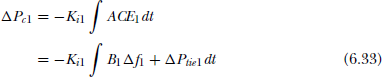
As with single area control, the speed is changed according to the changes of ∆ƒ and ∆Ptie1
Where B1 and B2 are frequency bias parameters. Now,
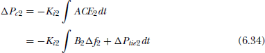
Ki1 and Ki2 are integrator gains if ∆PD1 and ∆PD2 are applied simultaeously.
Under steady state the outputs of all the blocks in two-area ALFC are constant. Under these conditions
if ∆ƒ1 (s.s) a = ∆ƒ2 (S.S) = ∆ƒ (s.s) and ∆Ptie2 (s.s) = –a12∆Ptie1 (s.s). We know that under normal or steady state, the two errors must be zero.
Here under steady state ∆ƒ and ∆Ptie must be zero i.e., each area has to supply its own load by itself and the errors must be zero.
If ∆Ptie1, ∆ƒ is zero and |B2 + a12| ≠ 0, the value of determinant will be zero. Similarly, if B1 = 0 and B2 ≠ 0, the determinant ≠ 0, and vice versa.
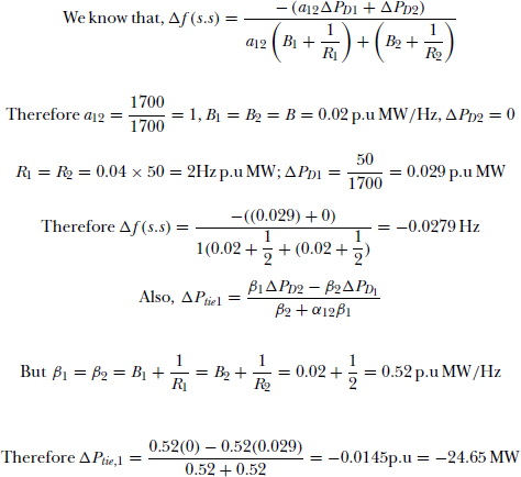
Example 6.1
A two-area load frequency control has identical area parameters as shown below:
Total area capacity = 1700 MW
Nominal frequency = 50 Hz
Inertia constant = 6
Regulation = 4 percent
Nominal operating load = 1000 MW
Damping coefficient = 0.02p.u MW/Hz
For a load increase of 50 MW in Area 1, find ∆ƒ (s.s) and ∆Ptie1.
Solution:
Example 6.2
A two-area load frequency control has the following specifications:
Area 1:
Rated capacity 100MW
Regulation 4
Load 60MW
Area 2:
Rated capacity 30MW
Regulation 3
Load 10MW
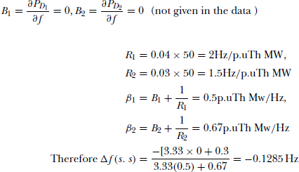
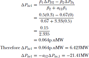
For a change in load of 10MW in Area 2, find the power transmitted in the line and the operating frequency.
Solution:
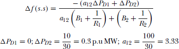
Therefore operating frequency = f deg + Δf (s. s) = 49.87 Hz
Example 6.3
A two-area system interconnected through a tie-line has the following parameters.
| Area 1 | Area 2 | |
|---|---|---|
Maximum capacity
|
2500 MW
|
1500 MW
|
Regulation
|
2.5 percent
|
3 percent
|
Nominal frequency
|
50 Hz
|
50 Hz
|
Gain, Kp
|
80 Hz/p.u Th MW
|
70 Hz/rm p.u Th MW
|
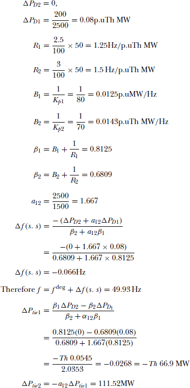
Find ∆ƒ(s.s) and tie-line power for a load change of 200MW in Area 1.
Solution:
Example 6.4
Two alternators rated 500MW and 800MW are operating is parallel with governor droop characteristics of 4 percent and 5 percent respectively, from no load to full load. If a load of 900MW is connected to the system, find the share of load for each alternator, and also the system operating frequency. Assume the no load frequency to be 50 Hz.
Solution:
The state of the above system is represented in Fig. 6.5.:
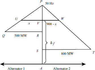
Fig 6.5
Let Alternator 1 share ‘x’ MW of load from a total of 900MW. Therefore Alternator 2 shares (900–x) MW of load. From ∆PVU and ∆PRQ, we know that
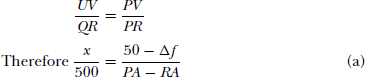
But at full load for Alternator 1, the regulation is 4 percent
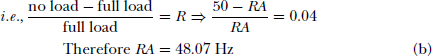
Substituting (b) in (a), we get x(PA − 48.07) = (50 − Δf)500
Therefore x(50 − 48.07) = (50 − Δf)500 ⇒ x = 12953.7 − 259.06Δf (d)
Similarly from ΔPVW and ΔPST
Solving (d) and (e) x = 391.85 MW, ∆ƒ = 48.49 Hz
Therefore Load shared by Alternator 1 = 391.85MW
Load shared by Alternator 2 = 900 – 391.85 = 508.15 MW
frequency ∆f = 48.49 Hz