6.1 LOAD FREQUENCY CONTROL OF TWO-AREA SYSTEM
In single-area frequency control we could represent the frequency deviations by a single variable ∆ƒ. However, in the case of two-area frequency control, we assume each area to be individually strong, and have inter connected through a weak tie-line. This therefore leads us to the assumption that the frequency deviation in the two areas can be represented by two variables ∆ƒ1, and ∆ƒ2 respectively.
An extended power system can be divided into a number of load frequency control areas inter connected by means of tie-lines. Consider a two-area case connected by a single tie-line as shown in Fig 6.1. Power systems are inter connected for economy and continuity of power supply. For an inter connected operation, incremental efficiencies, fuel costs, water availabilities, spinning reserve allocation and area commitments are important considerations in preparing load dispatch schedules.
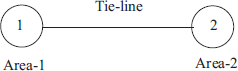
Fig 6.1 Inter connected two-area system
6.1.1 Flat Frequency Control of Inter Connected System
Let two generating stations are connected by a tie-line.
If there is a load increment at station B, the kinetic energy of the generators reduce to absorb the load, and generations increase at both stations A and B. Further, the frequency will be less than normal at the end of the governor response period as shown in Fig 6.2 (b).
The load increment will be shared partly by A and partly by B. The tie-line power flow will change and hence if a frequency controller is placed at B then it will shift the governor characteristics at B parallel to itself as shown in Fig. 6.2. (c). The frequency will therefore be restored to its normal value, reducing the change in generation in A to zero.
If there is a load increment comes at station A, initially the generation in both A and B changes to absorb the additional load. However, the additional load is absorbed by B only. Station A does not absorb the load changes in the steady state. It is possible that in an inter connected operation, a given station can be made to absorb the load changes occurring elsewhere in the system so long as the controlling station has the capability to absorb the change.
The same analysis can be applied to a two-area system.
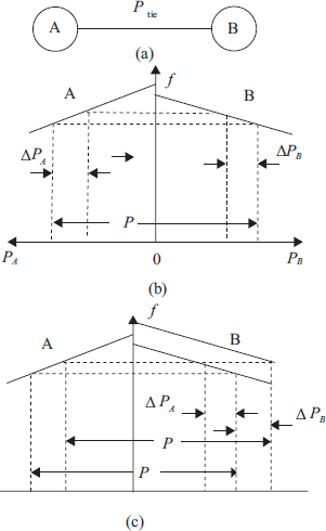
Fig 6.2 (a) Two inter connected stations. (b) Uncontrolled system with load more on station B and (c) Frequency controller located at station B
Assumptions made in the analysis of a two-area system
- The overall governing characteristics of the operating units in any area can be represented by linear curves of frequency versus generation.
- The governors in both areas start acting simultaneously to changes in their respective areas.
- Secondary control devices act after the initial governor response is complete.
6.1.2 Tie-Line Bias Control
With tie-line bias controllers located in both areas the control action is complete in all the cases. For the case where the tie-line bias controller in ‘A’ initiates action for local load changes, the response is as shown in Fig. 6.3.
The response to controller action is similar for load changes in B when the controller in B initiates regulating action. The governor action is not changed until the load change becomes effective in the area. This avoids unnecessary change in generation, frequency or tie-line power. The controller in the area where load change occurs acts is such a manner that the area absorbs its own load change. A single shift to the governor characteristics is necessary to restore both frequency and tie-line power to normal. A smooth cooperative regulation is thus achieved with a tie-line bias control scheme for the two area system.
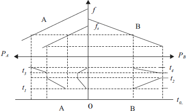
Fig 6.3