Each of the four Design Grids has been engineered to serve a different purpose. Grids #1 and #2 are most useful when you are sketching out mosaic images or planning a model that will be viewed from the top looking down. Grids #3 and #4 take a different approach and allow you to imagine a LEGO model as seen from the side.
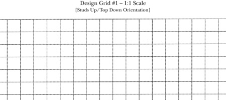
Grid #1 allows you to look down on a model from above, straight down on the studs. As you can see by the sample shown in Figure B-1, each square is exactly the size of a real 1x1 brick.
Grid #2 is unique among the Design Grids in that it is the only one of the four that does not have lines drawn to exactly the size of real LEGO elements. Instead, it is made up of a 32x32 field of squares that are sized to fit on a single page. You can use it to help you plan a mosaic that fits onto LEGO’s common 32x32 waffle baseplate. As you can see in Figure B-2 the grid also has another special feature.
The added feature of this grid is that it makes it easy for you to give any location on the baseplate a name by which you can reference it. You can use the letters (along the left side) and numbers (along the top) next to the grid to pinpoint a particular location within the design. For example, in Figure B-3, you can see that I have marked an X in some of the squares on the grid. I can identify these locations by the letter/number combination. In other words, you simply find the row and column that meet at the square you want to think about and you see which letter and number match that square.
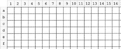
Figure B-2. Just like the reference markers found on a real map, the numbers and letters help you determine where bricks need to go.
You may also find these identifiers useful when transferring your mosaic design from paper to actual elements. You can count out the numbers and letters on your actual baseplate and use them to distinguish where you should place certain bricks or plates. In Figure B-3, you can see elements indicated on the Design Grid at locations A1, B2, and C3. On the right, you see the actual LEGO pieces in exactly the same locations on the baseplate.
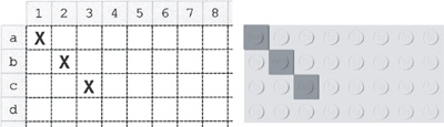
Figure B-3. This side-by-side comparison shows how marks made on the Design Grid translate into the position of real pieces on the actual baseplate.
You may not always need to reference pieces by their exact location, but at other times, you may find this letter and number system very useful.
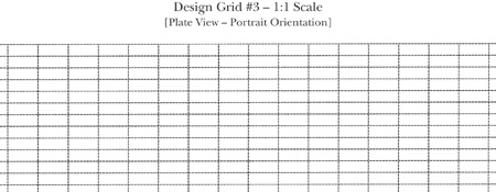
Grid #3 allows you to plan a model as though you are looking at it from the side. A portion of the grid is shown in Figure B-4. You can see that the boxes (also known as cells) on this grid are much shorter. In fact, each box is the height and width of a standard 1x1 plate as seen from the side. This configuration is referred to as plate view.
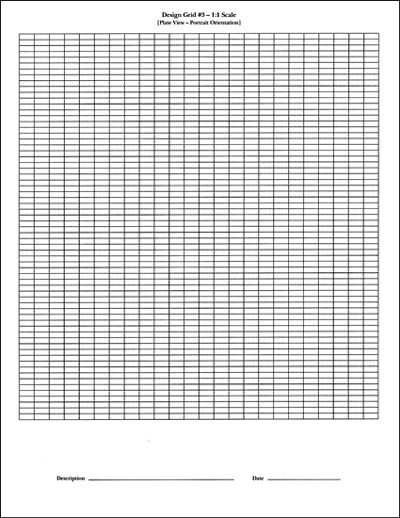
Three of these boxes, just as with the real plates, equal one standard 1x1 brick in height. The page itself is set up just the way you would read a normal book, with the short sides of the page at the top and bottom.
This is known as portrait perspective (see Figure B-5).
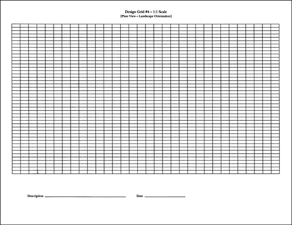
Grid #4 consists of the same sized squares as Grid #3, but the entire page is oriented with the long sides of the page at the top and bottom. This is known as landscape perspective. The image of the grid (shown in Figure B-6) has been reduced in size so that you can see the orientation of the squares as they appear on a full page.