
I’ve talked about many aspects of design theory and how they apply to the model of the fictional Space Shuttle Triton. It’s now time for you to become familiar with the instructions for building this creation.
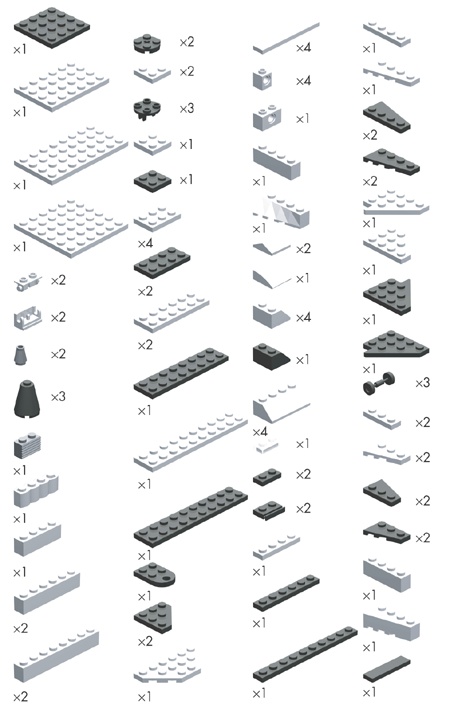
I’ve included these instructions, along with build notes for each step. In Figure 10-12, you’ll find the list of the pieces you need to make this model. As always, don’t forget that substitution is a regular part of the building process when you’re making original models. If you don’t have every piece shown in the Bill of Materials, try to find a part or several parts that you can substitute for what is shown.
As with many of the models featured in this book, I built a version of the shuttle using computer software. This allowed me to mark each building step as I went along so that the program could then create an image for each stage of the construction. I use a program called LeoCAD, but other such programs are available.
Note
For a complete list of software you can use to design LEGO models on your computer, visit my website: www.apotome.com/links.html.
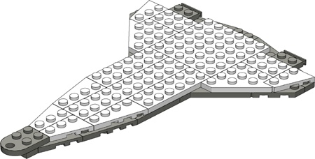
Figure 10-13 shows you something similar to what you saw in Figure 10-4 earlier in the chapter.

This is the bottom layer of the wing structure. Look for a place within each model you design that makes sense as a starting point. In the case of the shuttle, the wings serve as an excellent base upon which to build the remainder of the craft.
The second layer of plates (as seen in Figure 10-14) are close to following the outline of the lower layer, but they do not match it exactly. This slight mismatch is the result of a conscious design decision. If you look at the real shuttle’s wings, you’ll see some of the protective heat absorbing material lining the front edges. By leaving some of the lower layer exposed, you create the illusion of that material on the model. This is a slight variation on the staggering technique you first saw back in Chapter 2.
The body of the shuttle model is very simple. At this scale, there isn’t room for as much detail as perhaps you’d like. As you see in Figure 10-15, you’ve just concentrated on trying to create the basic outline for the cargo bay.

Figure 10-15. The inserted image in the top right corner gives you a building hint, since it’s hard to see just what pieces should go at the end of the craft. In this case, it’s two 1x1 Technic bricks that go on either side of the 1x2 grille brick.
The 1x4 brick across the middle helps support the plates that you’ll add in the next step. You need to make similar decisions about detail when you create your own models. Don’t be afraid to design as realistically as possible, but don’t overwhelm a small model with more details than it can handle. Ultimately you need to ask yourself, “Does this model look like what I want it to look like?” As long as the answer is yes, then you’ve got a successful design.
Because this model is for display purposes and isn’t meant to be functional, creating a hollow cargo bay isn’t important to the success of the design. Instead, use 4xN plates (see Figure 10-16) to join the side walls together.
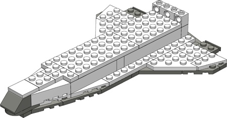
Figure 10-16. More Technic bricks near the back of the body. This time it is obvious which pieces to use, so no insert is necessary.
This gives you a ship that is sturdier and holds up better to being whooshed about the room. A larger-scale model of the shuttle might have included such things as retractable landing gear or movable wing flaps. But it might have been difficult to try to make them work on the small scale you’re working with here. You need to decide how many details to include or leave out based on the size of your project.
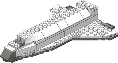
The shuttle model that you’re building is really fairly small, so it comes together quite quickly. In Figure 10-17, you can see that, by step 5, you’re already adding the 45-degree slopes that form the cargo bay doors.
Although it’s hard to distinguish in these black-and-white instructions, the 1x2 plate nearest to the nose of the ship is a transparent element. Remember, the doors aren’t functional—they are only for show. But at this scale, such a design decision is acceptable as long as it fits with the look and feel of the rest of the model.
You can sometimes add several unrelated portions of the model all in the same step. Figure 10-18 shows an example of this.

Figure 10-18. As long as nothing is blocked from view by the new elements, you can add any number of pieces in a single step.
In this step, you add the tail (mounted on a 2x3 plate), the cowlings near the engines (the 2x2 33-degree slopes hanging off the 1x2 brick hinges), and also the curved slope that becomes the top of the crew cabin.
Use a black 1x4 tile on the tail to represent some of the protective material that is located there on the real shuttle. Don’t worry about re-creating the specific parts of the tail that move (located at the very rear). If you add in too much detail, this may take away from the look of the rest of the model. Remember that you don’t want to start adding a greater level of detail in one area if you are keeping other areas sparse.
The tail itself is held in place by the studs on the 2x3 plate below it. The thickness of the plate is nearly identical to the distance between the studs. That’s what allows it to be wedged in like that.
Sometimes you need to turn the model in one direction or another to more clearly see a building step. Figure 10-19 is an example of this. In this step, turn the ship so that the engines are facing the out. This allows you to see where the 1x1 and 2x2x2 cones that are used to create the engines go.
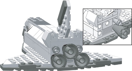
Figure 10-19. You now get to see why I used Technic bricks to build the end of the body. The insert shows the rear of the shuttle without all the cones in place. This should help you understand how I attached these pieces.
Although the engines might not be exactly the right size for this scale, they are very close. Additionally, they match the pattern in which the engines are mounted as accurately as possible. That helps better match your micro model with the real thing. Once again, it’s about capturing the look, not the minutest detail.
Again, in Step 8, reposition the ship as shown in the illustration (Figure 10-20). This time, you’re looking at it from underneath so that you can see where to attach the landing gear. In a case like this where you are adding pieces to the underside of another element, you can count the tubes to see where to make the attachment. When you’re adding pieces on top of others, you usually use the studs as guides instead.

Figure 10-20. Using only a picture and no words, I can accurately describe where to attach the landing gear on the lower wing.
The two sets of wheels closer to the back are mounted slightly differently than the front landing gear. Each of the rear wheels has a 2x2 cylindrical plate sandwiched between itself and the underside of the shuttle. This causes the nose of the craft to sit slightly lower when you are finished. You can see this effect in Figure 10-21 in step 9. This duplicates the angle at which the real shuttle points when it is taxiing after a landing.
Figure 10-21 reveals that step 9 isn’t really a step at all; rather, it is an overview of what the completed model should look like.

You might want to use this last step to determine where to add decals (printed from your computer) or small detail pieces. In this case (Figure 10-21), I just add a runway made of tiles beneath the model to give it a sense of realism.
In the end, don’t be concerned if something isn’t quite right. This is a model made from LEGO bricks after all. Disassemble the section you feel is lacking and rebuild it using different pieces, different combinations of pieces, or alternate colors. In the case of the shuttle example, I built a prototype for the purpose of documenting it in this book. I rebuilt the nose two or three times before I hit on the combination of plates, tiles, and slopes that I felt best represented the shape I wanted to re-create. Similarly, I adjusted the pattern of plates I used to make the wings several times until I felt they looked right but were also strong enough to support the remainder of the pieces I was going to add on top.
The engines, on the other hand, were the first and only pieces I selected for that portion of the model. They just seemed to work right off the bat. The point is that not every section of a model comes together perfectly on your first attempt. Some turn out exactly as you intend, whereas others require you to change parts or techniques again and again until things begin to look better.
Now you’ve seen how to design and build an original model from scratch. You’ve looked at various ways to capture details from real life objects and how to make wise design decisions when translating that object into LEGO pieces. When you’re done, you might find yourself asking, “What now?”
The first thing you’ll probably want to do is display your model somewhere so that other people can see it. The display might be real, such as in an office cubicle or on a shelf in your LEGO building area. For this, you might want to build something on which to set your model (such as the runway shown in Figure 10-21), or you may want to go even further and build a complete diorama in which to showcase it. Or, perhaps you want to display your model virtually. You can take pictures of it and display them on the Internet for your friends and others to enjoy. The choice is up to you, but chances are that once you’ve accomplished a successful design, you will want to share it in one way or another.