Day 26. VLAN Concepts
CCENT 100-101 ICND1 Exam Topics
![]() Describe how VLANs create logically separate networks and the need for routing between them.
Describe how VLANs create logically separate networks and the need for routing between them.
![]() Explain network segmentation and basic traffic management concepts.
Explain network segmentation and basic traffic management concepts.
Key Points
Most large networks today implement virtual local area networks (VLAN). Without VLANs, a switch considers every port to be in the same broadcast domain. With VLANs, switch ports can be grouped into different VLANs, in effect segmenting the broadcast domain. Today, we review VLAN concepts, consider traffic types, discuss VLAN types, and review the concept of trunking including Dynamic Trunking Protocol (DTP).
VLAN Concepts
Although a switch “out of the box” is configured to have only one VLAN, normally a switch will be configured to have two or more VLANs. Doing so creates multiple broadcast domains by putting some interfaces into one VLAN and other interfaces into other VLANs.
Reasons for using VLANs include the following:
![]() Grouping users by department instead of by physical location
Grouping users by department instead of by physical location
![]() Segmenting devices into smaller LANs to reduce processing overhead for all devices on the LAN
Segmenting devices into smaller LANs to reduce processing overhead for all devices on the LAN
![]() Reducing the workload of STP by limiting a VLAN to a single access switch
Reducing the workload of STP by limiting a VLAN to a single access switch
![]() Enforcing better security by isolating sensitive data to separate VLANs
Enforcing better security by isolating sensitive data to separate VLANs
![]() Separating IP voice traffic from data traffic
Separating IP voice traffic from data traffic
![]() Assisting troubleshooting by reducing the size of the failure domain (the number of devices that can cause or be effected by a failure)
Assisting troubleshooting by reducing the size of the failure domain (the number of devices that can cause or be effected by a failure)
Benefits of using VLANs include the following:
![]() Security: Sensitive data can be isolated to one VLAN, separating it from the rest of the network.
Security: Sensitive data can be isolated to one VLAN, separating it from the rest of the network.
![]() Cost reduction: Cost savings result from less need for expensive network upgrades and more efficient use of existing bandwidth and uplinks.
Cost reduction: Cost savings result from less need for expensive network upgrades and more efficient use of existing bandwidth and uplinks.
![]() Higher performance: Dividing flat Layer 2 networks into multiple logical broadcast domains reduces unnecessary traffic on the network and boosts performance.
Higher performance: Dividing flat Layer 2 networks into multiple logical broadcast domains reduces unnecessary traffic on the network and boosts performance.
![]() Broadcast storm mitigation: VLAN segmentation prevents a broadcast storm from propagating throughout the entire network.
Broadcast storm mitigation: VLAN segmentation prevents a broadcast storm from propagating throughout the entire network.
![]() Ease of management and troubleshooting: A hierarchical addressing scheme groups network addresses contiguously. Because a hierarchical IP addressing scheme makes problem components easier to locate, network management and troubleshooting are more efficient.
Ease of management and troubleshooting: A hierarchical addressing scheme groups network addresses contiguously. Because a hierarchical IP addressing scheme makes problem components easier to locate, network management and troubleshooting are more efficient.
Traffic Types
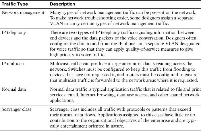
A key factor for VLAN deployment is understanding the traffic patterns and the various traffic types in the organization. Table 26-1 lists the common types of network traffic that you should evaluate before placing devices and configuring VLANs.
Types of VLANs
Some VLAN types are defined by the type of traffic they support; others are defined by the specific functions they perform. The principal VLAN types and their descriptions follow:
![]() Data VLAN: Configured to carry only user-generated traffic, ensuring that voice and management traffic is separated from data traffic.
Data VLAN: Configured to carry only user-generated traffic, ensuring that voice and management traffic is separated from data traffic.
![]() Default VLAN: All the ports on a switch are members of the default VLAN when the switch is reset to factory defaults. The default VLAN for Cisco switches is VLAN 1. VLAN 1 has all the features of any VLAN, except that you cannot rename it and you cannot delete it. It is a security best practice to restrict VLAN 1 to serve as a conduit only for Layer 2 control traffic (for example, CDP), supporting no other traffic.
Default VLAN: All the ports on a switch are members of the default VLAN when the switch is reset to factory defaults. The default VLAN for Cisco switches is VLAN 1. VLAN 1 has all the features of any VLAN, except that you cannot rename it and you cannot delete it. It is a security best practice to restrict VLAN 1 to serve as a conduit only for Layer 2 control traffic (for example, CDP), supporting no other traffic.
![]() Black hole VLAN: A security best practice is to define a black hole VLAN to be a dummy VLAN distinct from all other VLANs defined in the switched LAN. All unused switch ports are assigned to the black hole VLAN so that any unauthorized device connecting to an unused switch port will be prevented from communicating beyond the switch to which it is connected.
Black hole VLAN: A security best practice is to define a black hole VLAN to be a dummy VLAN distinct from all other VLANs defined in the switched LAN. All unused switch ports are assigned to the black hole VLAN so that any unauthorized device connecting to an unused switch port will be prevented from communicating beyond the switch to which it is connected.
![]() Native VLAN: This VLAN type serves as a common identifier on opposing ends of a trunk link. A security best practice is to define a native VLAN to be a dummy VLAN distinct from all other VLANs defined in the switched LAN. The native VLAN is not used for any traffic in the switched network unless legacy bridging devices happen to be present in the network or a multiaccess interconnection exists between switches joined by a hub.
Native VLAN: This VLAN type serves as a common identifier on opposing ends of a trunk link. A security best practice is to define a native VLAN to be a dummy VLAN distinct from all other VLANs defined in the switched LAN. The native VLAN is not used for any traffic in the switched network unless legacy bridging devices happen to be present in the network or a multiaccess interconnection exists between switches joined by a hub.
![]() Management VLAN: A VLAN defined by the network administrator as a means to access the management capabilities of a switch. By default, VLAN 1 is the management VLAN. It is a security best practice to define the management VLAN to be a VLAN distinct from all other VLANs defined in the switched LAN. You do so by configuring and activating a new VLAN interface.
Management VLAN: A VLAN defined by the network administrator as a means to access the management capabilities of a switch. By default, VLAN 1 is the management VLAN. It is a security best practice to define the management VLAN to be a VLAN distinct from all other VLANs defined in the switched LAN. You do so by configuring and activating a new VLAN interface.
![]() Voice VLANs: The voice VLAN feature enables switch ports to carry IP voice traffic from an IP phone. The network administrator configures a voice VLAN and assigns it to access ports. Then when an IP phone is connected to the switch port, the switch sends CDP messages that instruct the attached IP phone to send voice traffic tagged with the voice VLAN ID.
Voice VLANs: The voice VLAN feature enables switch ports to carry IP voice traffic from an IP phone. The network administrator configures a voice VLAN and assigns it to access ports. Then when an IP phone is connected to the switch port, the switch sends CDP messages that instruct the attached IP phone to send voice traffic tagged with the voice VLAN ID.
Voice VLAN Example
Figure 26-1 shows an example of using one port on a switch to connect a user’s IP phone and PC. The switch port is configured to carry data traffic on VLAN 20 and voice traffic on VLAN 150. The Cisco IP Phone contains an integrated three-port 10/100 switch to provide the following dedicated connections:
![]() Port 1 connects to the switch or other VoIP device.
Port 1 connects to the switch or other VoIP device.
![]() Port 2 is an internal 10/100 interface that carries the IP Phone traffic.
Port 2 is an internal 10/100 interface that carries the IP Phone traffic.
![]() Port 3 (access port) connects to a PC or other device.
Port 3 (access port) connects to a PC or other device.
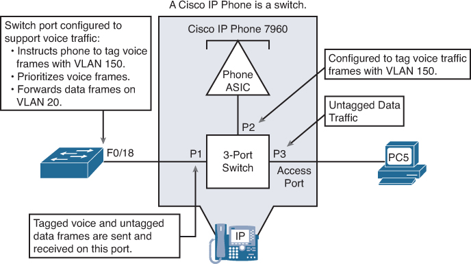
The traffic from the PC5 attached to the IP Phone passes through the IP Phone untagged. The link between S2 and the IP Phone acts as a modified trunk to carry both the tagged voice traffic and the untagged data traffic.
Trunking VLANs
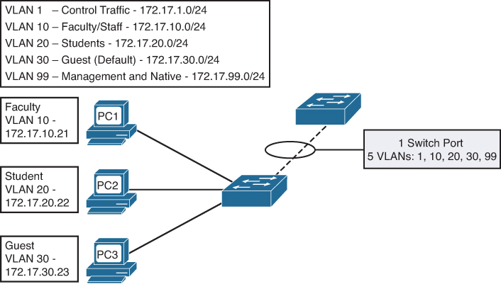
A VLAN trunk is an Ethernet point-to-point link between an Ethernet switch interface and an Ethernet interface on another networking device, such as a router or a switch, carrying the traffic of multiple VLANs over the singular link. A VLAN trunk allows you to extend the VLANs across an entire network. A VLAN trunk does not belong to a specific VLAN; rather, it serves as a conduit for VLANs between switches. Figure 26-2 shows a small switched network with a trunk link between S1 and S2 carrying multiple VLAN traffic.
When a frame is placed on a trunk link, information about the VLAN it belongs to must be added to the frame. This is accomplished by using IEEE 802.1Q frame tagging. When a switch receives a frame on a port configured in access mode and destined for a remote device through a trunk link, the switch takes apart the frame and inserts a VLAN tag, recalculates the frame check sequence (FCS), and sends the tagged frame out the trunk port. Figure 26-3 shows the 802.1Q tag inserted in an Ethernet frame.
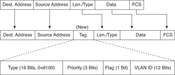
The VLAN tag field consists of a 16-bit Type field called the EtherType field and a Tag control information field. The EtherType field is set to the hexadecimal value of 0x8100. This value is called the tag protocol ID (TPID) value. With the EtherType field set to the TPID value, the switch receiving the frame knows to look for information in the Tag control information field. The Tag control information field contains the following:
![]() 3 bits of user priority: Used to provide expedited transmission of Layer 2 frames, such as voice traffic.
3 bits of user priority: Used to provide expedited transmission of Layer 2 frames, such as voice traffic.
![]() 1 bit of Canonical Format Identifier (CFI): Enables Token Ring frames to be carried across Ethernet links easily.
1 bit of Canonical Format Identifier (CFI): Enables Token Ring frames to be carried across Ethernet links easily.
![]() 12 bits of VLAN ID (VID): VLAN identification numbers.
12 bits of VLAN ID (VID): VLAN identification numbers.
Note
Although 802.1Q is the recommended method for tagging frames, you should be aware of the Cisco proprietary legacy trunking protocol called Inter-Switch Link (ISL).
Dynamic Trunking Protocol
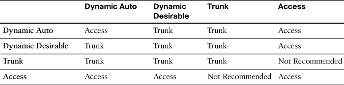
Dynamic Trunking Protocol (DTP) is a Cisco-proprietary protocol that negotiates both the status of trunk ports as well as the trunk encapsulation of trunk ports. DTP manages trunk negotiation only if the port on the other switch is configured in a trunk mode that supports DTP. A switch port on a Cisco Catalyst switch supports a number of trunking modes. The trunking mode defines how the port negotiates using DTP to set up a trunk link with its peer port. The following is a brief description of each trunking mode:
![]() If the switch is configured with the switchport mode trunk command, the switch port periodically sends DTP messages to the remote port, advertising that it is in an unconditional trunking state.
If the switch is configured with the switchport mode trunk command, the switch port periodically sends DTP messages to the remote port, advertising that it is in an unconditional trunking state.
![]() If the switch is configured with the switchport mode trunk dynamic auto command, the local switch port advertises to the remote switch port that it is able to trunk but does not request to go to the trunking state. After a DTP negotiation, the local port ends up in the trunking state only if the remote port trunk mode has been configured so that the status is on or desirable. If both ports on the switches are set to auto, they do not negotiate to be in a trunking state. They negotiate to be in the access mode state.
If the switch is configured with the switchport mode trunk dynamic auto command, the local switch port advertises to the remote switch port that it is able to trunk but does not request to go to the trunking state. After a DTP negotiation, the local port ends up in the trunking state only if the remote port trunk mode has been configured so that the status is on or desirable. If both ports on the switches are set to auto, they do not negotiate to be in a trunking state. They negotiate to be in the access mode state.
![]() If the switch is configured with the switchport mode dynamic desirable command, the local switch port advertises to the remote switch port that it is able to trunk and asks the remote switch port to go to the trunking state. If the local port detects that the remote has been configured as on, desirable, or auto mode, the local port ends up in the trunking state. If the remote switch port is in the nonegotiate mode, the local switch port remains as a nontrunking port.
If the switch is configured with the switchport mode dynamic desirable command, the local switch port advertises to the remote switch port that it is able to trunk and asks the remote switch port to go to the trunking state. If the local port detects that the remote has been configured as on, desirable, or auto mode, the local port ends up in the trunking state. If the remote switch port is in the nonegotiate mode, the local switch port remains as a nontrunking port.
![]() If the switch is configured with the switchport nonegotiate command, the local port is then considered to be in an unconditional trunking state. Use this feature when you need to configure a trunk with a switch from another switch vendor.
If the switch is configured with the switchport nonegotiate command, the local port is then considered to be in an unconditional trunking state. Use this feature when you need to configure a trunk with a switch from another switch vendor.
Table 26-2 summarizes the results of DTP negotiations based on the different DTP configuration commands on a local and remote port.