
Customizing AutoCAD and AutoCAD LT can increase your efficiency and productivity. The time spent in preparation will be paid back many times. Before you start customizing, you need to know some basics that apply to almost all customization tasks. After you understand these basics, the process becomes much easier.
Overall, AutoCAD LT offers less customizability than AutoCAD; however, most of the features in this chapter apply to both AutoCAD and AutoCAD LT.
The capability to customize AutoCAD and AutoCAD LT is based on the fact that many of the support files are text files that you can edit yourself. The menu customization and tool palettes are in XML files that you customize by using the Customize User Interface Editor and the Customize dialog box. Table 29.1 lists the most important files and their functions.
Figure 29.1 shows a portion of one of these files, acad.pgp, which lists command shortcuts, or aliases. The equivalent file for AutoCAD LT is acadlt.pgp.
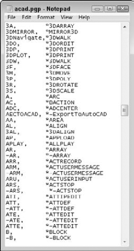
Table 29.1. Customizable Files
AutoCAD Filename | AutoCAD LT Filename | Function |
|---|---|---|
|
| Custom dictionary file. You can add words to the custom dictionary for use with the SPELL command. |
|
| Program parameters file. This file is generally used to create keyboard shortcuts (called aliases) for commands. |
|
| Customization file. You modify this file by using the Customize User Interface Editor. This file replaces the CUI files used in 2006 through 2009 releases of AutoCAD and AutoCAD LT. |
| N/A | AutoLISP routines used by AutoCAD's main menu. If you create your own menus, you can have an MNL file with the same name as your menu for AutoLISP routines (AutoCAD only). |
|
| Configuration file for storing digitizer and other settings. Usually, you should use the Options dialog box to make these selections, instead of manually editing this file. See Appendix A for more information about this file. |
| Dialog Control Language (DCL) file. This file describes dialog boxes. You usually don't edit this file, but you can write your own DCL files to create dialog boxes you display with AutoLISP. You would not create custom DCL files for AutoCAD LT because it lacks support for AutoLISP. | |
|
| Linetype definition file. You can also create your own linetype definition (LIN) files or add your own definitions to one of the standard linetype files. |
| N/A | AutoCAD's AutoLISP files. You create these files from scratch. You can edit or add to these files to automatically load AutoLISP routines. Other customizable LSP files are discussed in Chapter 35 (AutoCAD only). |
| N/A | AutoCAD's multiline library file (AutoCAD only). |
|
| AutoCAD's hatch pattern file. You can also create your own. |
|
| Plot configuration files. You can also create your own. A PC3 file contains all configuration settings for a plotter. This is not a text file; you customize it by using a dialog box. For more information, see Chapter 17 and Appendix A. |
|
| Font mapping file. Use this file to specify substitute fonts, whether or not the original fonts are available on your system. |
|
| PostScript support file. It is used for the PSOUT and PSFILL commands. PSFILL is in AutoCAD only. |
|
| Slide library file, used for hatch pattern examples in menus. You can use this file or create your own slide libraries. This is not a text file; see Chapter 30 for an explanation of how to create a slide library. |
|
| A script file that you create and name. Script files are macros of commands and options that run automatically. |
|
| A shape file that you create and name. Shape files usually hold fonts, but can hold other shapes as well. A shape file is then compiled into a file with an SHX extension for more efficient use. |
| N/A | A list of ARX (an interface for programming AutoCAD) applications that load automatically (AutoCAD only). You must create this file, if you are going to load ARX files, by using this method. |
|
| Font mapping for the appearance of text in the MTEXT editor. |
|
| A file that defines every conceivable type of unit. |
To customize AutoCAD or AutoCAD LT, you edit a text file, use the Customize User Interface Editor, or use the Customize dialog box. To edit files in text-only (ASCII) format, you need a text editor, which is like a word processor but does not place any formatting codes in the file. For most of the ASCII files, you can use Notepad, which comes with Windows. All major word processors let you save documents as text documents — just remember not to click that Save button until you've specified the right file format. Files that are not in ASCII format generally have an interface, such as a dialog box, in the program for editing them.
Before editing any preexisting files, back them up. The system of editing menus and toolbars in a dialog box helps to protect your system from errors that you might make when customizing, but if you want to undo all your changes, you need a backup. You should back up in three stages:
Back up the original file as it came out of the box. Keep a disc with all the customizable files that you might ever edit in their original form.
After you edit the file, back it up before each editing session. This way you always have your most recent version of the file. If you make a mistake, it's easy to copy that file on top of the one with the mistake and put everything back to normal.
After you edit a file, back it up again so that you have it in case your hard drive crashes, or you need to reinstall AutoCAD or AutoCAD LT.
Note
To find acad.cuix or acadlt.cuix, choose Application Button
This means that you should have two disks, one with the original customizable files and one with your most recent versions of them. At the very least, these disks should contain the following files:
acad.linandacadiso.lin/acadlt.linandacadltiso.linacad.lspandacaddoc.lsp(AutoCAD only)acad.mln(AutoCAD only)acad.mnl(AutoCAD only)acad.cuix/acadlt.cuixacad.patandacadiso.pat/acadlt.patandacadltiso.patacad.pgp/acadlt.pgp
You may also want to back up templates that you've created.
Tip
If you get into trouble, you can find an original copy of many of the customizable files at C:Program FilesAutoCAD 2010UserDataCacheSupport for AutoCAD and C:Program FilesAutoCAD LT 2010UserDataCacheSupport for AutoCAD LT (if you used the default installation location).
You'll use these disks not only when you make a mistake, but also whenever you need to reinstall AutoCAD or AutoCAD LT, whether due to hard-drive failure, a virus on your system, the replacement of your old computer with a new one, or some other reason. Also, when you upgrade AutoCAD or AutoCAD LT to the next release, you can usually continue to work with your familiar, customized files.
Note
In Appendix A, I discuss the Migrate Custom Settings dialog box that appears when you install or upgrade AutoCAD or AutoCAD LT. This dialog box helps you to bring existing customizable files into your new installation of AutoCAD or AutoCAD LT.
For many customization tasks, you need to work with commands. When you create a script file, which is a series of commands, or when you edit the menu file, you need to type out the commands that you want to execute. In these cases, the customizable files can only contain the command-line form of the commands. As a result, you need to learn a whole new way of working — the old-fashioned way, by typing commands on the command line.
Tip
If you're not sure of the command name but you know the menu or toolbar item, execute the command on the menu or toolbar and then press Esc. You see the command name on the command line.
A number of commands have a non-dialog-box version. Many commands can be executed in their command-line version by placing a hyphen (-) before the command name. For some commands that have no command-line equivalent, you can use system variables to create the same effect. Table 29.2 lists command-line versions of commands that you can use for customization.
Table 29.2. Command-Line Forms of Commands
Command | Command | Command-Line Form | |
|---|---|---|---|
3DCONFIG | -3DCONFIG (AutoCAD only) | ACTSTOP | -ACTSTOP (AutoCAD only) |
ACTUSERMESSAGE | -ACTUSERMESSAGE (AutoCAD only) | ARCHIVE | -ARCHIVE (AutoCAD only) |
ARRAY | -ARRAY | ATTACH | -ATTACH |
ATTDEF | -ATTDEF | ATTEDIT | -ATTEDIT |
ATTEXT | -ATTEXT | BEDIT | -BEDIT |
BHATCH | -BHATCH | BLOCK | -BLOCK |
BOUNDARY | -BOUNDARY | COLOR | -COLOR |
COPYTOLAYER | -COPYTOLAYER | DATAEXTRACTION | -DATAEXTRACTION (AutoCAD only) |
DDPTYPE | PDMODE, PDSIZE | DDVPOINT | VPOINT |
DGNADJUST | -DGNADJUST (AutoCAD only) | DGNATTACH | -DGNATTACH |
DGNEXPORT | -DGNEXPORT | DGNIMPORT | -DGNIMPORT |
DIMINSPECT | -DIMINSPECT | DIMSTYLE | -DIMSTYLE |
DSETTINGS | ORTHO, SNAP, GRID, ISOPLANE, AUTOSNAP, SNAPTYPE, DYNMODE, DYNPROMPT | DWFADJUST | -DWFADJUST (AutoCAD only) |
DWFATTACH | -DWFATTACH | EATTEXT | -EATTEXT (AutoCAD only) |
ETRANSMIT | -ETRANSMIT | GROUP | -GROUP |
HATCHEDIT | -HATCHEDIT | HYPERLINK | -HYPERLINK |
IMAGE | -IMAGE | IMAGEADJUST | -IMAGEADJUST |
INSERT | -INSERT | INTERFERE | -INTERFERE (AutoCAD only) |
LAYDEL | -LAYDEL | LAYER | -LAYER |
LAYMCH | -LAYMCH | LAYMRG | -LAYMRG |
LINETYPE | -LINETYPE | LWEIGHT | -LWEIGHT |
-MLEDIT (AutoCAD only) | MTEXT | -MTEXT | |
OBJECTSCALE | -OBJECTSCALE | OPENSHEETSET | -OPENSHEETSET (AutoCAD only) |
OSNAP | -OSNAP | PAN | -PAN |
PARAMETERS | -PARAMETERS | PARTIALOAD | -PARTIALOAD (AutoCAD only) |
PDFADJUST | -PDFADJUST | PDFATTACH | -PDFATTACH |
PLOT | -PLOT | PLOTSTAMP | -PLOTSTAMP |
PLOTSTYLE | -PLOTSTYLE | PROPERTIES | CHANGE, CHPROP, -COLOR, -LAYER, -LINETYPE, CELTYPE, CELTSCALE, ELEV, THICKNESS |
PSETUPIN | -PSETUPIN | PUBLISH | -PUBLISH (AutoCAD only), +PUBLISH |
PURGE | -PURGE | REFEDIT | -REFEDIT |
RENAME | -RENAME | RENDER | -RENDER (AutoCAD only) |
SCALELISTEDIT | -SCALELISTEDIT | STYLE | -STYLE |
TABLE | -TABLE | TEXT | -TEXT |
TOOLBAR | -TOOLBAR | UNITS | -UNITS |
VBALOAD | -VBALOAD (AutoCAD only) | VBARUN | -VBARUN (AutoCAD only) |
VIEW | -VIEW | VISUALSTYLES | -VISULSTYLES (AutoCAD only) |
VPORTS | -VPORTS | WBLOCK | -WBLOCK |
WSSAVE | -WSSAVE | XBIND | -XBIND |
XREF | -XREF |
In addition, you can use the dimension variables to format dimensions in place of using the DIMSTYLE command, which opens the Dimension Style Manager dialog box. Chapter 15 discusses DIMSTYLE command.
The FILEDIA system variable determines whether a dialog box opens for commands, such as SAVEAS and OPEN, that request filenames. When FILEDIA is set to 1, the default dialog boxes open. The CMDDIA system variable affects the display of command-related dialog boxes or in-place editors for such commands as LEADER and QLEADER.
Note
Even if FILEDIA is set to 1, if a script or AutoLISP/ObjectARX program is active, the command prompt is used rather than a dialog box. You can still set the FILEDIA system variable to 0, but be sure to change it back again at the end of your script or program. (Scripts, but not AutoLISP or ObjectARX programs, are available in AutoCAD LT.)
Placing comments in customized files to explain how you customized them is standard practice. Although your customizations may seem obvious at the time, if you go back to a file later, you may not understand what you were trying to accomplish. Also, other people may need some explanation.
You can place comments in many of the customizable files by placing a semicolon (;) before any line of text.
Now that you know the basics of customizing files, you can move on to creating keyboard shortcuts and customizing toolbars.
You can create keyboard shortcuts for commands, thereby enabling you to enter commands on the command line without remembering and typing the full command name. Shortcuts are stored in the acad.pgp file for AutoCAD and the acadlt.pgp file for AutoCAD LT. To open the PGP file, choose Manage tab
You can use this file for three purposes:
The auto-complete feature completes commands you start to type in the dynamic input tooltip or on the command line. Type as many letters as you know, and then press Tab or Shift+Tab to cycle through all the commands that start with those letters.
Note
You can also create keyboard shortcuts, such as Ctrl+G or F11, for commands. See Chapter 33 for more information. The shortcuts in acad.pgp and acadlt.pgp use only letters and numbers.
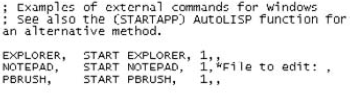
In AutoCAD, you can use the acad.pgp file to create shortcuts to Windows programs. For example, you may often open Notepad while customizing files. The acad.pgp file includes the following three shortcuts to Windows programs:
EXPLORER, START EXPLORER, 1,,
NOTEPAD,  START NOTEPAD, 1,*File to edit: ,
PBRUSH,  START PBRUSH,  1,,
Note
The AutoCAD LT acadlt.pgp file does not support shortcuts to Windows programs.
The first column is the command name that you type at the command line. The second column is the command that you want Windows to execute. The number 1 specifies to start the application but not to wait until you've finished using it. This lets you return to your drawing at any time. After the 1, you can finish with two commas. However, notice that the Notepad entry has *File to edit: before the last comma. This is a prompt that you see on the command line. Type the name of the file to edit, and Windows opens it in Notepad. (You need to type in the complete path of the file.) To open Notepad without a file, press Enter at the *File to edit: prompt.
Most of the acad.pgp or acadlt.pgp files contain aliases, or keyboard shortcuts, for common commands. You can change these or add your own. After you become used to them, it's often faster to type shortcuts at the command line than to click the ribbon button or menu item, especially if your hands are already on the keyboard. You cannot include a command option in the acad.pgp file. To do that, you need to create a ribbon button, a menu item (accessible from the menu bar), a toolbar button, or an AutoLISP routine. Remember that the menu bar and toolbars are not displayed in the default AutoCAD and AutoCAD LT workspaces.
Note
The Express Tools contain an Alias Editor that enables you to edit the acad.pgp file through a dialog box interface. Choose Express Tools tab
Note
Quickkey is an expanded replacement for acad.pgp that supports commands with their options, such as ZOOM Previous. Look in SoftwareChapter 29Quickkey.
The format for creating an alias is as follows:
Shortcut,*Full command name
Refer to Figure 29.1 for some examples of command aliases. Note that the space between the columns is not necessary — it simply improves readability.
Note
The acad.pgp and acadlt.pgp files contain a special User Defined Command Aliases section at the end for creating your own aliases. Aliases in this section override aliases in the main section.
You can use an alias transparently if the command itself can be used transparently. Aliases in script files or menus can fail when used on an installation of AutoCAD that doesn't have those aliases defined. Note that you cannot use control or function keys in command aliases in the PGP file.
Warning
If you're working on someone else's computer, don't do the following exercise without that person's permission. It isn't good computer etiquette to modify other people's files without asking first.
STEPS: Customizing the acad.pgp File
Start AutoCAD or AutoCAD LT.
Prepare and insert a backup medium, such as a flash drive or CD-RW. Do one of the following:
If you have AutoCAD, type explorer

If you have AutoCAD LT, open Windows Explorer by right-clicking the Windows Start button and choosing Explore.
Note
To find the location of
acad.pgporacadlt.pgp, choose Application Button
Find
acad.pgporacadlt.pgp, click it, and drag it to the drive for your backup medium (in the Folders window). Windows copiesacad.pgporacadlt.pgpto the backup medium. If you haven't already backed up your other customizable files and you're using AutoCAD, copyacad.lin, acad.lsp, acad.mln, acad.mnl, acad.cuix, andacad.patto the backup medium as well. If you're using AutoCAD LT, back up theacadlt.lin, acadlt.cuix, andacadlt.patfiles.In AutoCAD or AutoCAD LT, choose Manage tab
In AutoCAD only, scroll down roughly two screens until you see the three Windows commands, as shown in Figure 29.2. Place the cursor at the end of the PBRUSH line and press Enter.
In AutoCAD only, type the following and press Enter (the uppercase format and spaces are used to match the format of the rest of the file):
WORDPAD, START WORDPAD, 1,,
Look at the next section of
acad.pgporacadlt.pgp. Read the guidelines for creating new aliases.Scroll down until you see the following two lines:
CH,    *PROPERTIES
-CH,    *CHANGE
The alias for the CHANGE command follows the guideline of using a hyphen to distinguish command-line versions of commands. Suppose you have trouble finding that hyphen quickly (you end up typing
=chinstead). You want to change the alias tocg(with no hyphen).Scroll down to the end of the file until you see the User Defined Command Aliases section. Place the cursor at the very end of the file and press Enter. Type the following and press Enter (don't worry about the spaces; I've matched the spacing of the
acad.pgporacadlt.pgpfile):CG, *CHANGE
Choose File
Close Notepad. Generally,
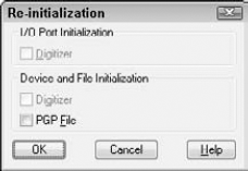
acad.pgporacadlt.pgpis accessed only when you load a new or existing drawing. However, you can use the REINIT command to reload the file at any time. Type reinitCheck the PGP File check box and click OK. In your drawing, draw a line anywhere on the screen.
Type cg
If you are using AutoCAD, type wordpad
Do not save your drawing.
Note
The edited acad.pgp file is on the DVD in the Results folder. Although you made only two changes, if you want, you can copy the acad.pgp or acadlt.pgp file from the DVD over your original acad.pgp or acadlt.pgp file. Of course, you can make additional changes to suit your needs.
In this section, I explain how to use the Customize User Interface Editor to customize toolbars, including the Quick Access toolbar. You can create toolbars, create custom commands, design toolbar buttons, delete toolbars that are no longer needed, customize existing toolbars, and add or remove commands from the Quick Access toolbar. Note that the default workspace for AutoCAD and AutoCAD LT, 2D Drafting & Annotation, shows only one toolbar, the Quick Access toolbar.
In the default workspace, the ribbon replaces toolbars, except for the Quick Access toolbar. You can customize the Quick Access toolbar so that the commands that you use most frequently are easily accessible. The Classic workspace includes the traditional menu and toolbars from previous releases. You can add toolbars to any workspace.
Note
The CUI files used in the 2006 through 2009 releases of AutoCAD and AutoCAD LT have been replaced by the new CUIx file format. The CUIx file format is a package file format which contains the data for all the user interface elements defined in the file and the custom images that the commands in the file reference.
Tip
To display a toolbar from the 2D & Drafting Annotation or 3D Modeling workspace, click the Customize button (the drop-down arrow) on the right end of the Quick Access toolbar, and choose Show Menu Bar. From the menu bar, choose Tools
Note
For information on customizing the ribbon and other aspects of the user interface, see Chapter 33. Note that when you apply a change to the user interface, all aspects of the interface are updated, including the Workspaces feature, which provides a way to create and save multiple interface displays. Therefore, you may find that various toolbars, palettes, and so on suddenly open when you return to your drawing. To learn how to control workspaces, see Appendix A.
Tip
Typing quickcui opens a simplified view of the Customize User Interface Editor. You can also access this simplified view by right-clicking toolbars or tool palettes, and choosing Customize (or Customize Commands). This view lets you easily drag commands onto a toolbar or tool palette. Click the right arrow at the bottom of the dialog box to expand it to its full size.
How many times have you found yourself typing a command because you couldn't quickly find an equivalent button on a toolbar, or because it was on a flyout that required too many clicks to access? In addition, think of how often you start a command with a toolbar button, only to return to the keyboard to type in a simple option.
You can customize the toolbars to make your work easier and faster. You can create new toolbars from scratch, or edit existing ones. You can even create your own toolbar buttons. When you create a toolbar button, you can attach any sequence of commands to it, such as a complex macro, the command name defined by an action macro, or even an AutoLISP expression (for AutoCAD only).
Although classic toolbars do not appear in the default workspace in AutoCAD or AutoCAD LT, you may want to use the Classic workspace, which includes toolbars, or add a toolbar to the default workspace or a custom workspace. Therefore, the skills for customizing toolbars are very useful.
You can customize any existing toolbar by removing buttons that you rarely use. To remove buttons from a toolbar, follow these steps:
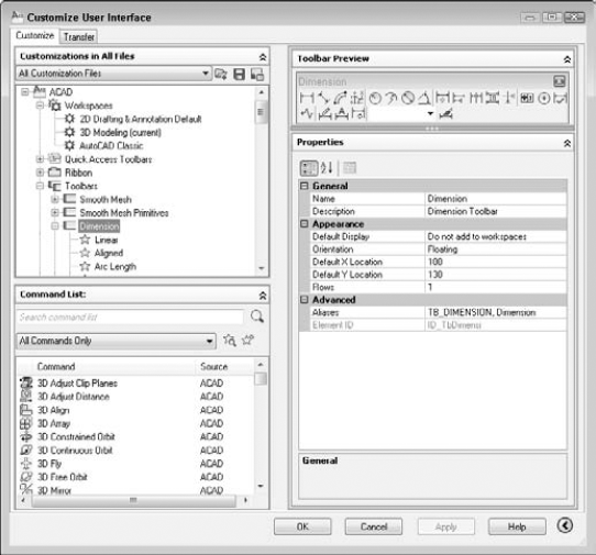
Choose Manage tab
In the Customizations in All Files pane, with All Customization Files selected in the drop-down list, double-click the Toolbars item to expand the list of all the toolbars.
Double-click the toolbar that you want to work with to expand its list of buttons.
Right-click the button that you want to remove, and choose Remove from the shortcut menu.
You may want to create your own toolbar from scratch that contains buttons for commands that you use often. To avoid changing the main menu, you should use the custom.cuix file. If this is not be loaded by default, you can find it in the Support folder with the main customization file, although that comes with AutoCAD or AutoCAD LT. This file is a separate partial customization file. Using a partial customization file helps you to keep your customization files separate from the standard menu file (acad.cuix or acadlt.cuix). For more information on partial customization files, see Chapter 33.
To create a new toolbar, first choose custom.cuix from the drop-down list at the top of the Customizations in All Files pane of the Customize User Interface Editor. Then right-click the Toolbars item and choose New Toolbar.
Tip
You can also create a new partial customization file. On the Transfer tab of the Customize User Interface Editor, choose New File from the Customizations In drop-down list on the right. From the drop-down list, choose Save As. In the Save As dialog box, name the new file. Make sure that you use a name that is different from all other customization files. To use the file, go to the Customize tab and choose Main Customization File from the drop-down list in the Customizations in All Files pane. Then click the Load Partial Customization File button to the right of the drop-down list. In the Open dialog box, locate the partial CUIx file and click Open. Again choose Main Customization File from the drop-down list. You should now see the new file listed under the expanded Partial Customization Files item.
A new toolbar appears under the Toolbars item, named Toolbar1. You can immediately rename this toolbar or right-click it and choose Rename. If you click Apply, a small, new toolbar appears on the screen. You may need to reposition the Customize User Interface Editor to see the new toolbar.
The new toolbar is just a baby, but with some nurturing, by adding buttons to it, it grows automatically.
After you've created a new toolbar, you need to add buttons to it. One method is to add a command from the Command List pane of the Customize User Interface Editor. Follow these steps:
In the Customizations in Main File pane, choose All Customization Files from the drop-down list.
If you are working in a partial customization file, double-click the Partial Customization Files item to expand it.
Expand the Toolbars item to display the list of toolbars.
Select the toolbar that you want to add buttons to.
From the Categories drop-down list of the Command List pane, choose All Commands or a category that displays the command that you want to add.
Drag the command from the list to the toolbar item in the Customizations in All Files pane until you see an arrow pointing to the toolbar.
When you create a new toolbar, it appears in the Toolbar Preview pane. You can drag commands from the Command List to the preview of the toolbar. (However, for the first button, you need to use the method just described.) Also, to quickly add a new button to an existing toolbar, you can right-click the toolbar and choose Customize from the bottom of the list of toolbars. The simplified view of the Customize User Interface Editor opens, listing all the commands. You can then drag the command you want to the desired location on the toolbar.
Tip
To check the results of your customization before closing the Customize User Interface Editor, click Apply and then move the editor so that it doesn't cover the new toolbar. If you are satisfied, click OK to close the editor.
You can also move a button from one toolbar to another. In the Customize User Interface Editor, expand the toolbar that contains the button that you want to move. Then drag the button to your new toolbar or to any other toolbar. This moves the button, deleting it from the original toolbar.
To copy a button from another toolbar, use the same technique as for moving a button, but hold down the Ctrl key as you drag a button from one toolbar to another toolbar. This procedure leaves the first toolbar intact. You can also copy a button by right-clicking over the button, choosing Copy, and then pasting it into the desired location.
Tip
To help organize your toolbars, you can add separator spaces. With the toolbar expanded, right-click the button above where you want to add the space and choose Insert Separator. You can also drag buttons to change their order, either in the Customizations in All Files pane or in the Toolbar Preview pane.
You can also create your own commands from scratch, which you display on a toolbar as a button. This involves creating a custom command macro and then choosing or designing a button icon. Follow these steps to create a custom command:
In the Customizations in All Files pane, double-click the Toolbars item and choose the toolbar that you want to work with.
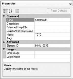
In the Command List pane, click the Create a New Command button. The Properties pane shows the properties of the new command, as shown in Figure 29.5.
In the Name text box, replace the default name (Command1) with your own name. This name appears as the title for a tooltip, so don't make it too long.
Type a helpful description in the Description text box. This text appears in a tooltip to further explain the function of the command.
Write the macro in the Macro text box. The
^C^Ccancels any other command that may be active when you use the command. After that, place any valid command string or action macro name as it would be typed on the command line, or even an AutoLISP expression (for AutoCAD only).Note
You need to use menu syntax for the macro. I explain the details of creating command strings in Chapter 33, where I cover customizing menus in depth.
From the Categories drop-down list, choose Custom Commands. Drag the new command onto a toolbar.
Select the button in the Command List pane. In the Button Image pane, choose a button icon from the list of button icons, or click Edit to create a custom image for your button, as explained in the next section.
Click Apply and click the OK button of the Customize User Interface Editor to close it.
The Button Editor, shown in Figure 29.6, enables you to make your own button icons. In the Customizations in All Files pane of the Customize User Interface Editor, select the toolbar command that you want to work with. Open the Button Editor by clicking Edit in the Button Image pane of the Customize User Interface Editor. You can choose one of the provided buttons and edit it — which I recommend — or start from scratch if you have artistic tendencies.
Note
To help you find the right button to edit, each button in the Button Image pane shows a tooltip with the name of its image file. When you click an image, the larger preview also displays the name of the image file.
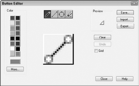
The center of the editing area shows an enlarged view of the button. You see the button's actual size to the right of the editing area of the dialog box. Check the Grid check box to show a grid of pixels — this is just a drawing aid. Choose a color from the color palette and then choose one of the four tools at the top of the dialog box:
The Pencil tool draws any shape. To draw, click anywhere to draw pixel by pixel, or drag across the editing area.
The Circle tool draws circles and ellipses. You click the center and drag out to the circumference to indicate the radius.
The Erase tool erases. You can click to erase pixel by pixel, or drag to erase a series of pixels.
Here are the other features of the Button Editor:
Click Clear to clear the editing area and start from scratch.
Click Import to load an existing button image that is stored externally of the CUIx file for editing. Button images are stored as BMP files in the CUIx package file.
Click Undo to undo your most recent action.
Click Save to save the custom image to a BMP file under a new name in the CUIx file.
Click Export to save the button image as a BMP file that is stored outside of the CUIx file. The default location is the Icons folder, which you can find by choosing Application Button
Click Close to close the Button Editor.
Click More to select a standard index color or true color.
If you edited an existing button and saved the changes, then you're done. However, if you saved your button image under another filename, you need to associate the new file with the toolbar button. In the Properties pane, click the Small Image text box, and then select the image from the palette of images or click the Ellipsis (...) button. If you click the Ellipsis button, browse to the BMP file and choose it. Click Open. This action imports the image file into the CUIx file and its name appears in the Small Image text box. You can now click Apply, or if you want to return to your drawing, click OK.
Tip
You can import icon images into the palette of images in the Button Image pane. Right-click the image palette and choose Import Image. After browsing to the image and importing it, you can assign it to any toolbar button.
If you think you might ever want to display large toolbar buttons, do the same for the Large Image text box. By default, when you create a button image, the Both option button is selected in the Button Image pane, so you create both a small and a large image. To display large toolbar buttons, choose Application Button
Flyouts are toolbars that expand from a toolbar button. You can use the Customize User Interface Editor to create your own flyouts, or you can use one of the existing flyouts. To use an existing flyout, just drag one toolbar onto another one. Expand the Toolbars item in the Customizations in All Files pane. Then expand the toolbar that you want to work with. In the same pane, locate the toolbar that you want to turn into a flyout, and drag it to any location on the expanded toolbar.
To create your own flyout from scratch, follow these steps:
Expand the Toolbars item in the Customizations in All Files pane.
Right-click any toolbar and choose New Flyout.
Right-click the new flyout (named Toolbar1 by default) and choose Rename. Type a name for the flyout.
From the Command List pane, drag commands to the flyout, using the same technique as described in the "Adding buttons" section earlier in this chapter.
You can remove custom commands that you added to the customization file and are no longer used. To remove a custom command, follow these steps:
Choose Manage tab
In the Command List pane, from the Categories drop-down list, choose Custom Commands.
From the Command list, right-click the custom command that you want to delete, and choose Delete from the shortcut menu.
Being able to access the commands that you use frequently is important, and the Quick Access toolbar allows you to do just that. The Quick Access toolbar is located in the upper-left corner of the application window, just to the right of the Menu Browser, and above or below the ribbon when it is displayed. The current workspace determines which commands are accessible from the Quick Access toolbar. By default, you can create, open, save, and plot a drawing, as well as undo or redo your most recent actions.
Note
Instead of assigning commands directly to a workspace to customize the Quick Access toolbar, you create a new toolbar just like you would a classic toolbar, as described earlier in this chapter. After you create a Quick Access toolbar, to display it in the application window, you assign the toolbar you created to a workspace instead of adding commands. This makes customizing the Quick Access toolbar consistent with other user interface elements. You can also now add drop-downs to group related commands together, and add ribbon controls to a Quick Access toolbar.
You can create custom Quick Access toolbars to display the commands that you might frequently use and want to access, no matter which toolbars or ribbon panels are currently displayed. To create a new Quick Access toolbar, display the Customize User Interface Editor, right-click the Quick Access Toolbars item, and choose New Quick Access Toolbar. After you create a new Quick Access toolbar, you must assign it to the Quick Access Toolbars node of a workspace in order to display it in the application window. Follow these steps:
Choose Manage tab
In the Customizations in All Files pane, right-click the Quick Access Toolbars item and choose New Quick Access Toolbar.
Right-click the new toolbar (named Quick Access Toolbar 2 by default) and choose Rename. Type a name for the toolbar and press Enter.
From the Command List pane, drag the commands that you want to display on the new Quick Access toolbar.
From the Customizations in All Files pane, expand the Workspaces item and select the workspace for which you want to display the new Quick Access toolbar when it is current.
In the Workspace Contents pane, click Customize Workspace.
From the Customizations in All Files pane, expand the Quick Access Toolbars item (if necessary) and check the Quick Access toolbar you want to display when the workspace is current.
In the Workspace Contents pane, click Done.
You can remove commands that you no longer use from a Quick Access toolbar. To remove a command, right-click over the command on the Quick Access toolbar and choose Remove from Quick Access Toolbar.
Drop-down menus on a Quick Access toolbar allow you to group multiple commands under a single button. They are just like a flyout on a classic toolbar, but the drop-down menu on a Quick Access toolbar is not a reference to another toolbar. To control the appearance and behavior of a drop-down menu, select it in the Customizations in All Files pane, and use the Properties pane.
Note
Drop-down menus for the Quick Access toolbar are new for AutoCAD 2010. They offer more flexibility in customizing this toolbar.
To add a drop-down menu, right-click the Quick Access toolbar in the Customizations in All Files pane of the Customize User Interface Editor, and choose New Drop-Down. Rename the drop-down menu, and then change its appearance and behavior from the Properties pane. After you have defined the drop-down menu, add commands to it from the Command List pane like you would for a toolbar. If you want to assign a default command to the drop-down menu, drag a command from the Command List pane to the Primary Command node under the drop-down menu.
STEPS: Customizing Quick Access Toolbars
Open Windows Explorer. Copy
acad.cuix(for AutoCAD) oracadlt.cuix(for AutoCAD LT) to a flash drive, a CD-RW, or yourAutoCAD Biblefolder as a backup. If you use a folder on your hard drive, be sure to press the Ctrl key as you drag the file so that you copy it instead of moving it. If you don't do this step, you won't have a way to undo the changes that you make to the menu file.Note
To find the location of these files, choose Application Button
Start a new drawing by using any template. Save the file as
ab29-01.dwgin yourAutoCAD Biblefolder.Right-click over the Quick Access toolbar and choose Customize Quick Access Toolbar to open the Customize User Interface Editor. You should see
All Customization Filesin the drop-down list.From the Command List drop-down list, choose All Commands. Find the
Donutitem and drag it to the right side of the Quick Access toolbar.From the Categories drop-down list in the Command List pane, choose the Modify category and find Polyline Edit. (This is the PEDIT command.) Drag it to the right of the Donut button.
Tip
To find a command in the long list, click any command and type the first letter of the command you want. The list jumps to the first command with that letter. You can then scroll down and quickly find the command you want.
With All Commands displayed in the Categories List, drag the Visual Styles Hidden command (for AutoCAD) or the Hide command (for AutoCAD LT) to the right side of the Quick Access toolbar.
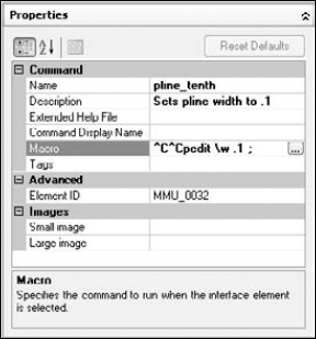
To create a custom command, click the Create a New Command button to the right of the All Commands drop-down list. You see the new command listed as Command1 in the Properties pane.
Complete the Properties pane, as shown in Figure 29.7. Type the macro as follows after the
^C^C(which is already there), being careful to also include the spaces:pedit w .1 ;
From the Categories drop-down list, choose Custom Commands. Drag the
pline_tenthcommand to the Quick Access toolbar. The button shows as a question mark because you haven't yet assigned it an icon.With the
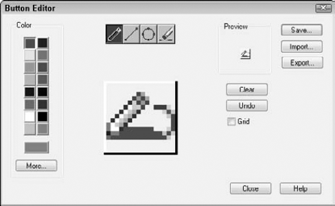
pline_tenthcommand still selected, in the Button Image pane, click the PEDIT icon. (It looks similar to the icon in Figure 29.8; its tooltip isRCDATA_16_PEDIT.) Then choose Edit to open the Button Editor.You want to change the button so that it looks as if a zero-width polyline is being changed to a wider polyline, because that's what the macro does. Click the red color. Choose the Pencil tool (by default, it is already chosen). Click the Grid check box to help you work. Click (or drag) the point of the Pencil tool in each box, using Figure 29.8 as a guide. (Figure 29.8 shows the button in black and white.) When you're done, click Save.
Tip
If you make a mistake, it's easy to correct it. If you place a red pixel over an existing black pixel, choose black and redraw the black pixel. If you place a red pixel in a wrong spot, choose the Erase tool and click the pixel.
In the Save Image dialog box, type pline_tenth in the Image Name text box and click OK. (Note that the file is saved in the
SupportIconsfolder by default.) Click Close.To assign the icon to the button, in the Button Image pane, click the Small Image item, and then scroll down to the bottom of the button image palette and choose the icon where it appears as the last button.
Click Apply. If necessary, move the dialog box so that you can see the Quick Access toolbar. If it seems okay, click OK to close the Customize User Interface Editor. (If not, continue to make changes in the dialog box.) The pline_tenth button updates to the new icon. The Quick Access toolbar should look like Figure 29.9.
Choose Home tab
Save your drawing.
Here's how the pedit macro that you used in the previous exercise works:
Peditissues the PEDIT command. The space afterpeditis equivalent to pressing Enter after you've typed the command on the command line. The PEDIT command then displays theSelect polyline or [Multiple]:prompt.The backslash (
) is a special character that pauses the macro for your input. When you select the polyline, the macro continues, displaying theEnter an option [Close/Join/Width/Edit vertex/Fit/Spline/Decurve/Ltype gen/Undo]:prompt.The
wthen specifies the Width option. The space following it is like pressing Enter. The PEDIT command then displays theSpecify new width for all segments:prompt.The macro then specifies 0.1. The space after it is like pressing Enter again. The PEDIT command then issues the
Enter an option [Close/Join/Width/Edit vertex/Fit/Spline/Decurve/Ltype gen/Undo]:prompt.The macro then uses a semicolon, which is used to specify pressing Enter at the end of a menu macro. This ends the command.
Undoing changes to the user interface
To undo the changes that you made, you need to take two steps. To unload a partial customization file that you have created, right-click it in the Customizations in All Files pane and choose Unload <file name>. This file is separate from the main customization file, so it doesn't affect the main customization file directly. The previous exercise didn't create a partial customization file.
To undo the changes that you made to the main customization file (acad.cuix or acadlt.cuix), copy the original file over the new one. To find the location of this file, choose Application Button
Close AutoCAD. In Windows Explorer, locate the backup copy that you made in Step 1 of the previous exercise. Expand the location of the current main customization file. Press Ctrl and drag the backup file to the current file of the same name.
When you open AutoCAD again, it will load the backup copy of the main customization file.
Tool palettes give you quick access to blocks, hatches, and commands. I cover tool palettes in Chapter 26. You can perform some customization directly on the tool palettes themselves. Here I explain the procedure for customizing the tool palettes by using the Customize dialog box.
To customize tool palettes, choose Manage tab
Use the Customize dialog box to customize tool palettes as follows:
Change the order of the tool palette tabs. Select one of the tabs in the Tool Palettes list and drag it up or down. You can also move the tabs directly on the tool palette by right-clicking the tab name and choosing Move Up or Move Down.
Create a new tool palette. Right-click and choose New Palette. Enter a name and press Enter. To create a new tool palette on the palette itself, right-click anywhere on the palette and choose New Palette.
Rename a tool palette. Click the palette's name to select it, and then click it again so that you see a border around the name. Enter a new name and press Enter. To rename a tool palette on the palette itself, right-click on the tab's name and choose Rename Palette.
Delete a tool palette. Select the tool palette, right-click and choose Delete. In the Confirm Palette Deletion dialog box, which warns you that deletion is permanent unless you first export the tool palette, click OK to delete the tool palette. You can also right-click any tool palette and choose Delete Palette.
Import a tool palette or group. Right-click a palette or group and choose Import. In the Import Palette dialog box, locate the XTP file and click Open.
Export a tool palette group. Right-click a palette or group and choose Export. In the Export Palette dialog box, choose the location for the file. You can change the name if you want. The tool palette is saved as an XTP file. Click Save.
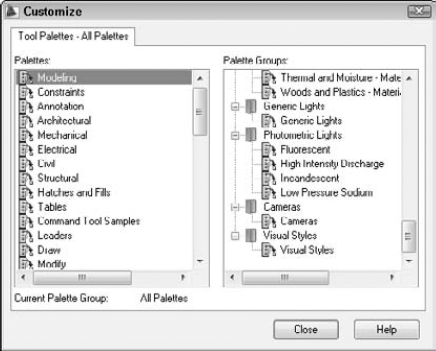
Organize tool palettes into groups. In the Palette Groups area, right-click and choose New Group. Enter a name for the group and press Enter. From the Palettes list on the left side of the dialog box, drag one or more tool palettes under the group name on the right, as you see in Figure 29.10.
Note that the tool palettes come with a large number of materials, as well as some visual styles, lights, and cameras (AutoCAD only).
In this chapter, I covered the basics of customizing AutoCAD and AutoCAD LT. You started to customize by:
Creating command shortcuts (aliases) in the
acad.pgporacadlt.pgpfileUsing the Customize User Interface Editor to create custom commands for use on the Quick Access toolbar and other toolbars
Customizing the Quick Access toolbar so that the commands that you need frequently are accessible
Creating your own toolbars that can contain any command sequence that you need
Customizing tool palettes, including importing, exporting, and creating groups
In the next chapter, you read about how to create macros with script files.