
AutoCAD and AutoCAD LT offer a number of ways to create curved objects. You can draw circles, arcs, ellipses, and donuts (also spelled as doughnuts). In this chapter, I also cover point objects, which are neither curves nor lines but don't deserve their own chapter.
Note
Several complex objects — such as polylines, splines, regions, and boundaries — involve curves. These are covered in Chapter 16.
Circles are common objects in drawings. In mechanical drawings, they often represent holes or wheels. In architectural drawings, they may be used for doorknobs, trash baskets, or trees. In electrical and piping schematics, they are used for various kinds of symbols.
Tip
You can also create a circle tangent to other objects by using the two-point (2P) method or three-point (3P) method, picking those points with the Tangent object snap.
Table 7.1. Six Ways to Draw a Circle
Description | |
|---|---|
Center, Radius | This option is the default. Specify the center and then the radius. You can type the radius as a distance, or pick a point where you want the circumference to be. |
Center, Diameter | Specify the center. Choose the |
2P (2 Points) | Choose the |
3P (3 Points) | Choose the |
Tan, tan, radius (Tangent, Tangent, Radius) | Choose the |
Tan, tan, tan (Tangent, Tangent, Tangent) | This option is available only from the Circle's drop-down list on the ribbon. You are prompted for three points, and AutoCAD automatically applies the Tangent object snap to each point. |
Drawing circles is fairly straightforward. Often, you can use object snaps to define part of the circle. In the following exercise, you practice using the most common methods of creating a circle.
Note
The drawing used in the following exercise on drawing circles, ab07-a.dwg, is in the Drawings folder on the DVD.
STEPS: Drawing Circles
Open
ab07-a.dwgfrom the DVD.Save the file as
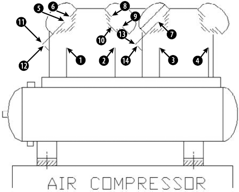
ab07-01.dwgin yourAutoCAD Biblefolder. This is a drawing of an air compressor from which all the circles have been removed. Make sure that Object Snap is turned on. Set a running object snap for Endpoint only. You should be in the default 2D Drafting & Annotation workspace (if necessary, choose it from the Workspace Switching button on the status bar).
Repeat the CIRCLE command by right-clicking and choosing Repeat Circle. Right-click and choose 2P from the shortcut menu. Pick the endpoints at

Repeat the CIRCLE command by pressing Enter. At the
Specify center point for circle or [3P/2P/Ttr (tan tan radius)]:prompt, pick the endpoint at
Repeat the CIRCLE command. At the
Specify center point for circle or [3P/2P/Ttr (tan tan radius)]:prompt, pick the endpoint at
Repeat the CIRCLE command by right-clicking and choosing Repeat Circle. At the
Specify center point for circle or [3P/2P/Ttr (tan tan radius)]:prompt, right-click and choose 3P. At theSpecify first point on circle:prompt, pick the endpoint at
For the last circle on the right, choose any method that you want to use to draw a circle. The circle should be the same size and placement as the second circle from the left.
Repeat the CIRCLE command. At the
Specify center point for circle or [3P/2P/Ttr (tan tan radius)]:prompt, choose the Center object snap and pickRepeat Step 9 to create a circle inside the circle whose center is at
Repeat the CIRCLE command. At the
Specify center point for circle or [3P/2P/Ttr (tan tan radius)]:prompt, pick the endpoint at
Repeat Step 11, choosing the endpoint at

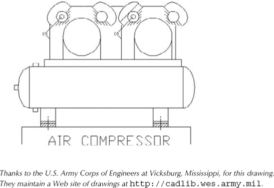
Save your drawing. It should look like Figure 7.2.
Note
It may have occurred to you that this task would have been easier if you could simply have copied one circle to another location instead of creating each circle from scratch. I cover copying in Chapter 9.
An arc is a portion of a circle. Therefore, to define an arc, you have to define not only a circle — for example, by specifying a center and a radius — but also the start and endpoints of the arc. The ARC command offers several methods for defining an arc. The method you pick depends on the information that you have about the arc that you want to draw.
Note
You can close an arc to create a circle by using the JOIN command. For more information, see Chapter 10.
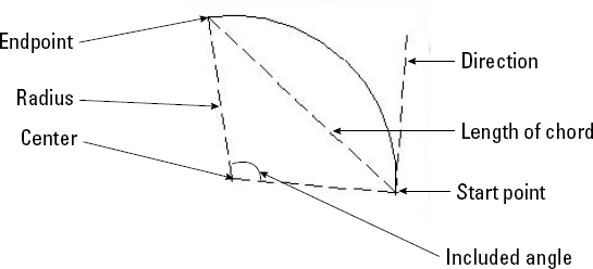
After you understand the parts of an arc, you can choose the options that suit your needs. Figure 7.3 shows the parts of an arc that you can use to draw an arc.
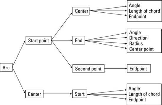
Figure 7.4 shows the flow of the arc options. When you start the ARC command, you have two options, Start Point and Center. Depending on how you start, more options become available.
You can also press Enter at the first arc prompt to draw a second arc starting from the endpoint of the most recently drawn arc, line, polyline, or other object. The new arc continues in the same direction as the end of the first object. The only other prompt is the endpoint.
When drawing an arc by using the Start, End, and Radius options, the three specifications actually define two possible arcs, one minor and one major. The ARC command draws the minor arc by default, in the counterclockwise direction. (A minor arc is less than half a circle.) If you enter a negative number for the radius, the command draws the major arc. The options requiring an angle also define two possible arcs, one drawn counterclockwise and one drawn clockwise. AutoCAD and AutoCAD LT draw the counterclockwise arc by default. If you type a negative number for the angle, the arc is drawn clockwise.
Note
The drawing used in the following exercise on drawing arcs, ab07-b.dwg, is in the Drawings folder on the DVD.
STEPS: Drawing Arcs
Open
ab07-b.dwgfrom the DVD.Save the file as
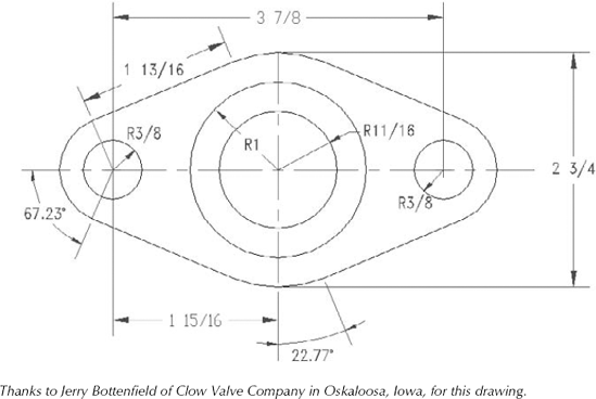
ab07-02.dwgin yourAutoCAD Biblefolder. Ortho mode is on, and units are set to Fractional. Right-click the Object Snap button on the status bar and set running object snaps for Intersection, Center, and Endpoint. Make sure that Object Snap is on. You should be in the default 2D Drafting & Annotation workspace (if necessary, choose it from the Workspace Switching button on the status bar). In this exercise, you draw part of the sealing plate shown in Figure 7.5 from scratch; therefore, the drawing is blank.Choose Home tab

Draw another line starting at 5-1/2,1-5/8 and draw it 2-3/4 units long in the 90-degree direction. These two lines are centerlines and would ordinarily appear in a different color and linetype than the object you're drawing. (You can read about colors and linetypes in Chapter 11.)
Choose Home tab
Use the Center object snap to draw another circle with the same center as the first circle and a radius of 1.
Draw a third circle, using the From object snap (Shift+right-click to open the Object Snap menu, and then choose From). For the base point, use the Center object snap and pick either of the first two circles that you drew. The offset is @-1-15/16,0 (this means 1-15/16 units to the left of the center of the first two circles). Its radius is ⅜.
Draw a fourth circle. Use the From object snap again. For the base point, use the Center object snap and pick either of the first two circles. The offset is @1-15/16,0. The radius is ⅜.

Specify start point of arc or [Center]:
Choose the From object snap. Base point:Use the Center object snap to pick the center of the leftmost circle. <Offset>:@-5/8,0Specify second point of arc or [Center/End]:
Right-click and choose Center. Use the Center object snap to pick the center of the leftmost circle. Specify endpoint of arc or [Angle/chord Length]:Right-click and choose Angle. Specify included angle:67.23Start the LINE command. At the
Specify first point:prompt, press Enter to continue the line in the same direction as the end of the arc. At theLength of line:prompt, type 1-13/16Start the ARC command again. Follow the prompts:
Specify start point of arc or [Center]:
Use the Endpoint object snap to pick the end of the line that you just drew. Specify second point of arc or [Center/End]:Right-click and choose Center. Use the Center object snap and pick any point on one of the large central circles. Specify end point of arc or [Angle/chord Length]:Use Endpoint object snap to pick the lower end of the vertical construction line.Repeat the ARC command. Follow the prompts:
Specify start point of arc or [Center]:
Right-click and choose Center. Use the Center object snap and pick any point on one of the large central circles. Specify start point of arc:Use the Endpoint object snap to pick the endpoint of the arc that you just completed. Specify end point of arc or [Angle/chord Length]:Right-click and choose Angle. Specify included angle:22.77Start the LINE command. At the
Specify first point:prompt, press Enter to continue the line in the same direction as the end of the arc. At theLength of line:prompt, type 1-13/16Start the ARC command. Follow the prompts:
Specify start point of arc or [Center]:
Use the Endpoint object snap to pick the endpoint of the line that you just drew. Specify second point of arc or [Center/End]:Right-click and choose End. Specify end point of arc: Choose the From object snap._from Base point:
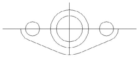
Use the Center object snap to pick the center of the rightmost circle. <Offset>:@5/8,0Specify center point of arc or [Angle/Direction/Radius]:rSpecify radius of arc:5/8Save your drawing. Your drawing should look like Figure 7.6. You can complete this drawing in Chapter 10 by creating a mirror image.
You can create ellipses (ovals) as well as elliptical arcs, which are partial ellipses. Like a circle, an ellipse has a center. The difference, of course, is that an ellipse has a longer radius along its major axis and a shorter radius along its minor axis.
You can draw an ellipse by defining the center first. Another option is to define the axis endpoints first. If you want to draw an elliptical arc, you must specify the start and end angles.
The default option is to specify endpoints 1 and 2 of the first axis. Then you specify the second distance of the axis, which is the distance from the first axis line to the circumference along the second axis.
Instead of specifying a second axis distance, you can choose the Rotation option. The Rotation option defines the minor axis by specifying an angle from 0 degrees to 90 degrees, which is the ratio of the major axis to the minor axis. (Actually, the command only accepts up to 89.4 degrees.) When the angle is 0, you get a circle. As the angle increases, the ellipse gets flatter and flatter until you reach 89.4 degrees. A 45-degree angle results in a minor axis whose length is the square root of the major-axis length.
Instead of specifying endpoints, you can use the Center option to specify the center of the ellipse. Then specify the endpoint of the first axis, which can be either the major or the minor axis. Finally, specify the other axis distance, which is the radius from the center to the circumference along the second axis. Again, instead of specifying the second axis distance, you can define the ellipse by using the Rotation option.
To draw an elliptical arc, use the Arc option of the ELLIPSE command. The first prompts are the same as for an ellipse. Then the command continues with the Specify start angle or [Parameter]: prompt, offering the following options:
Start angle. This option is the default. Specify the start angle, which the command redefines to start along the major axis. The command responds with the
Specify end angle or [Parameter/Included angle]:prompt.End angle. Specify the end angle to complete the ellipse arc.
Included angle. After specifying the start angle, you can complete the arc by specifying the included angle from the start point to the endpoint, going counterclockwise.
Parameter. Choose this option to define the arc portion by the ellipse's area rather than by its included angle (which defines the arc portion by its circumference). The command responds with the
Specify start parameter or [Angle]:andSpecify end parameter or [Angle/Included angle]:prompts. By typing in angles, you define the percent of the full ellipse's area that you want to include. (For example, starting at 15 degrees and ending at 105 degrees includes 90 degrees and therefore draws one quarter of an ellipse.) The options in brackets let you return to regular angle specification.
To draw an elliptical arc, choose Ellipse Arc from the Ellipse button's drop-down list or use the Arc option of the ELLIPSE command. When you draw an elliptical arc, the command introduces a helpful but sometimes confusing feature: While you're defining the arc angles, the command redefines 0 degrees along the major axis. This helps you to define the included angle in an orientation that relates to the ellipse, rather than the usual orientation where 0 degrees is to the right.
In this exercise, you practice drawing ellipses and elliptical arcs.
Note
The drawing used in the following exercise on drawing ellipses and elliptical arcs, ab07-c.dwg, is in the Drawings folder on the DVD.
STEPS: Drawing Ellipses and Elliptical Arcs
Open
ab07-c.dwgfrom the DVD.Save the file as
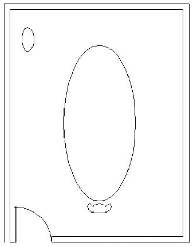
ab07-03.dwgin yourAutoCAD Biblefolder. The drawing shows an empty conference room. Snap is on, and set to 6″. Ortho mode and Object Snap should be on, with a running object snap set for Endpoint only. You should be in the default 2D Drafting & Annotation workspace (if necessary, choose it from the Workspace Switching button on the status bar).
Repeat the ELLIPSE command. Follow the prompts:
Specify axis endpoint of ellipse or [Arc/Center]:
Right-click and choose Arc (or choose Home tabDraw panelEllipse drop-down listElliptical Arc). Specify axis endpoint of elliptical arc or [Center]:Right-click and choose Center. Specify center of elliptical arc:Pick 8′,3′, a snap point. Specify endpoint of axis:Move the cursor to the right until the coordinates read 1′<0 and pick. (You can also look at the Dynamic Input tooltips.)Specify distance to other axis or [Rotation]:Move the cursor up until the coordinates read 6″<90 and pick. Specify start angle or [Parameter]:162Specify end angle or [Parameter/Included angle]:18Turn off Ortho mode. Start the LINE command. At the
Specify first point:prompt, use the Endpoint running object snap and pick the right side of the elliptical arc. At theSpecify next point or [Undo]:prompt, right-click the coordinates and choose Absolute (if necessary), and press and hold Shift+A to temporarily override Object Snap mode while you pick the snap point 8′6″,3′. End the LINE command.Start the LINE command. At the
Specify first point:prompt, use the Endpoint object snap to pick the left side of the ellipse arc. At theSpecify next point or [Undo]:prompt, press and hold Shift+A while you pick the snap point 7′6″,3′. End the LINE command.Start the ELLIPSE command. Follow the prompts:
Specify axis endpoint of ellipse or [Arc/Center]:
Right-click and choose Arc. Specify axis endpoint of elliptical arc or [Center]:Use the Endpoint object snap to pick the free endpoint of the line on the right. Specify other endpoint of axis:Use the Endpoint object snap to pick the free endpoint of the line on the left. Specify distance to other axis or [Rotation]:3<90(If you don't have Dynamic Input on and set to the default of relative coordinates, then type@before the distance.) Specify start angle or [Parameter]:Use the Endpoint object snap to pick the free endpoint of the line on the right. Specify end angle or [Parameter/Included angle]:Use Endpoint object snap to pick the free endpoint of the line on the left.Choose Home tab
Save your drawing. It should look like Figure 7.7.
A donut is a wide polyline that looks like two concentric circles, with the area between the circles filled in. You define a diameter for the inner and outer circles. Donuts are often used in electrical drawings to create symbols. If the inner circle's radius is zero, you create a filled-in circle.
The setting of the FILL command determines whether the donut is filled. Type fill
The DONUT command has the following prompts:
Specify inside diameter of donut <0.5000>. Type the diameter of the inside circle or pick two points to specify the inside diameter. The number in brackets is the last inside diameter that you defined, or 0.5 if you haven't previously used the DONUT command in this drawing session.Specify outside diameter of donut <1.0000>. Type the diameter of the outside circle or pick two points to specify the outside diameter. The outside diameter must be larger than the inside diameter. The number in brackets is the last outside diameter that you defined, or 1.0 if you haven't previously used the DONUT command in this drawing session.Specify second point. If you define the inside or outside diameter by picking a point, the command asks for a second point. Use this technique if you're using object snaps to define the diameters.Specify center of donut or <exit>. Specify the center of the donut. Pressing Enter ends the command.
Note
You can use the hatch feature to fill in any object with a solid fill, with a great deal more flexibility in the shape of your objects. (Chapter 16 discusses hatching.) As a result, the DONUT command is not as essential as it once was.
A point simply marks a coordinate. Points are generally used for reference. It is sometimes helpful to mark a point that you will use later as a guide to place an object or to help you return an object to its original position. When it's no longer needed, you may erase the point. This is a typical construction method. In some cases, the From object snap or object snap tracking can be used rather than a point.
Note
The DIVIDE and MEASURE commands place point objects along an object. Chapter 12 covers these commands.
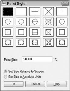
Because points can be hard to see, and because various disciplines have different conventions for drawing point objects, AutoCAD and AutoCAD LT provide 20 types of point styles that you can use in your drawing. Before you draw a point, you should set the point style. You can save this setting in your template.
Choose Home tab
To set the point style, click the box showing the style that you want. Then set the point size, which has the following options. When you are done, click OK to close the dialog box.
Set Size Relative to Screen. Use this option if you want the point to always appear the same size, no matter how much you zoom in and out — for example, when you're using the point as a reference. The size is set as a percentage of the screen. This option is the default, with the size set to 5 percent of the screen.
Set Size in Absolute Units. Use this option if you want the point to have a real size, just like any other object. The size is set in units. Use this option when you want the point to stay the same size relative to other objects in your drawing.
If BLIPMODE is on and you're using the first point style — a small dot — you cannot see the point until you use the REDRAW command to remove the blips. After you create a point, use the Node object snap to snap to the point.
Tip
If you're using the points for temporary reference, instead of erasing them, you can set the point style to the second style in the Point Style dialog box (no dot) before plotting. As a result, the points do not appear on your plot. You can also put your points on a layer with a Not Plottable property. (See Chapter 11 for more on layers.)
Note
The drawing used in the following exercise on drawing donuts and points, ab07-d.dwg, is in the Drawings folder on the DVD.
STEPS: Drawing Donuts and Points
Open
ab07-d.dwgfrom the DVD.Save the file as
ab07-04.dwgin yourAutoCAD Biblefolder. The drawing contains a rectangle and connecting wires for an electrical switch. Make sure that Object Snap is on. Set running object snaps for Endpoint, Center, Node, and Quadrant. This exercise assumes that you have Dynamic Input on, with the default setting of relative coordinates.Choose Home Tab

Specify a point:
Use the From object snap. (Shift+right-click to open the Object Snap shortcut menu.)Base point:Use the Endpoint object snap to pick the top-left corner of the rectangle. <Offset>:@.08,-.09Specify a point:Press Esc to complete the command.
Specify inside diameter of donut <0.5000>:
.04Specify outside diameter of donut <1.0000>:.06Specify center of donut or <exit>:Use the Node object snap to pick the point that you drew. Specify center of donut or <exit>:@.19,0Specify center of donut or <exit>:Start the POINT command again. Follow the prompts:
Specify a point: Press Shift+
right-click and choose Mid Between 2 Points from the shortcut menu. First point of mid:Use the Center object snap to pick the center of the right-hand donut. (You may have to press Tab until you get the Center object snap, and not a Quadrant object snap.)Second point of mid: Press Shift+right-click and choose Perpendicular from the shortcut menu. Press and hold Shift to temporarily turn on Ortho mode and pick the lower horizontal line of the rectangle. Release the Shift key. Specify a point:Press Esc.Choose Home tab
Specify first point:
Use the Quadrant object snap to pick the right (0 degrees) quadrant of the left donut. If you don't see the Quadrant SnapTip, press Tab until it appears. Specify next point or [Undo]:Use the Node object snap to pick the point that you just drew. End the LINE command.Save your drawing. It should look like Figure 7.9.
In this chapter, you learned how to draw curved objects and points in AutoCAD and AutoCAD LT. You discovered:
All the ways to draw circles
How to define and draw an arc
How to define an ellipse and an elliptical arc
How to draw a donut
How to set the point style and draw points
In the next chapter, you learn how to display your drawing for the greatest ease and comfort.