2
Aircraft Familiarity, Aircraft Design Process, Market Study
2.1 Overview
The ve ry first thing when studying aircraft design, as the topic of study in this book, is to get familiar with the product hardware as an introduction for the newly initiated reader. The road to a successful aircraft design has a formal step‐by‐step approach through phases of activity and must be managed. It is appropriate that readers should have some idea of how aircraft design projects are managed in a company and this is covered at an early stage of study. It is recommended that newly initiated readers read through this chapter because it tackles important parts of the work. To start a project requires generation of customer specifications, based on which the configured aircraft has the potential to succeed. A small part of the coursework starts in this chapter.
The go‐ahead for a programme comes after careful assessment of the design with a finalised aircraft configuration that evolved during the conceptual study (i.e. Phase I). The prediction accuracy at the end of Phase I must be within at least ±5%. In Phase II of the project, when more financing is available after obtaining the go‐ahead, the aircraft design is fine‐tuned through testing and more refined analysis. This is a time and cost consuming effort, with prediction accuracy now at less than ±2 to ±3%, offering guarantees to potential buyers. This book does not address project definition activities (i.e. Phase II); these are in‐depth studies conducted by specialists.
This book is concerned with the task involved in the conceptual design phase but without rigorous optimisation. Civil aircraft design lies within a verified design space; that is, it is a study within an achievable level of proven but leading‐edge technology involving routine development efforts. Conversely, military aircraft design lies within an aspirational design space; that is, it is a study of unproven advanced technology requiring extensive development efforts. Obviously, the latter is technologically more complex, challenging and difficult. Generally, the go‐ahead for a military combat aircraft project is preceded by a scaled down technology demonstrator aircraft to prove the technology concept.
This chapter covers the following topics:
- Section 2.2: Introduction
- Section 2.3: Aircraft Familiarisation (Civil/Military)
- Section 2.4: Aircraft Design Process; Systems Approach to Design and Project Phases
- Section 2.5: Four Phases of Aircraft Project
- Section 2.6: Task Breakdown in Each Phase and Functional Activities
- Section 2.7: Market Survey (Civil and Military)
- Section 2.8: Three Civil Aircraft Case Studies – Aircraft Specifications and Requirements for
- Section 2.9: Some Typical Military Aircraft Design Specifications
- Section 2.10: Airworthiness Requirements
- Section 2.11: Coursework Procedures
The coursework activity begins in Section 2.5 with a mock market survey to generate aircraft specifications and requirements and helps students understand its importance in the success or failure of a product. With guidance from the instructor, students conduct a mock market survey. Students generate a bar chart (i.e. Gantt chart) to monitor progress during the semester. The remainder of the chapter is recommended easy reading. The following would prove useful resources.
Jane's all the World's aircraft manual. This is an indispensable source of aircraft statistics vital for any aircraft design work.
Flight international. This was a weekly publication from the UK, now comes as an online publication. It is a newsletter‐type journal, providing the latest brief coverage of aerospace activities around the world.
Flight global. This is an on‐line news and information website related to the aviation and aerospace industries. It also offers aircraft diagrams and data.
Aviation week and space technology. This is a weekly publication from the United States that provides more in‐depth analysis of aerospace developments. It thoroughly covers the US scenario as well as worldwide coverage.
Interavia. A bimonthly publication from Switzerland that covered aerospace news and commercial airline business. It has now ceased to be published.
A list of aircraft design books is given in the Reference Section [1–24].
2.2 Introduction
Existing aircraft indicate how the market is served and should indicate what is needed for the future. Various aircraft have been designed, and new designs should perform better than any existing designs. Designers are obligated to search for proven advanced technologies that emerge. There could be more than one option so the design team must conduct trade‐off studies to arrive at a ‘satisfying’ design that will satisfy the customer. Balancing between ‘optimised’ and ‘satisfied’ aircraft design is the key to succeed. Economy and safety are possibly the strongest drivers in commercial transport. Aircraft design drivers for combat are performance capability and survivability (i.e. safety).
Despite organisational differences that exist among countries, one thing is common to all: namely, the constraint that the product must be ‘fit for purpose’. It is interesting to observe that organisational structures in the East and the West are beginning to converge in their approach to aircraft design. The West is replacing its vertically integrated setup with a major investor master company in the integrating role along with risk‐sharing partners. Since the fall of communism in Eastern Europe, the socialist bloc is also moving away from specialist activities to an integrated environment with risk‐sharing partners. Stringent accountability has led the West to move away from vertical integration – in which the design and manufacture of every component were done under one roof – to outsourcing design packages to specialist companies. The change was inevitable and it has resulted in better products and profitability, despite increased logistical activities.
The aircraft design process is now set in rigorous methodology and there is considerable caution in the approach due to the high level of investment required. The process is substantially front‐loaded, even before the project go‐ahead is given. In this chapter, generic and typical aircraft design phases are described as practised in the industry, which includes market surveys and airworthiness requirements. A product must comply with regulatory requirements, whether in civil or military applications. New designers must realise from the beginning the importance of meeting mandatory design requirements imposed by the certifying authorities.
Exceeding budgetary provisions is not uncommon. Military aircraft projects undergo significant technical challenges to meet time and cost frames; in addition, there could be other constraints. (The ‘gestation’ period of the Eurofighter project has taken nearly two decades. An even more extreme example is the Indian Light Combat Aircraft, which spanned nearly three decades; the original specifications likely to become obsolete by then.) Some fighter aircraft projects have been cancelled after the prototype aircraft was built (e.g. the Northrop F20 Tiger shark and the BAC TSR2). A good design organisation must have the courage to abandon concepts that are outdated and mediocre. The design of combat aircraft cannot be compromised because of national pride; rather, a nation can learn from mistakes and then progress step‐by‐step to a better future.
2.3 Aircraft Familiarisation
This section introduces generic civil and military aircraft. Geometric definitions relevant to aerodynamic considerations are addressed in Chapter 3 and detailed descriptions of various types of aircraft and their classification are provided in Chapter 4. A diagram of aircraft with major subassemblies as components is provided herein. Indeed, aircraft design has become highly modular in the interests of the ‘family’ concept, which facilitates low development cost by maintaining a high degree of parts commonality.
Aircraft span, length, and height are currently restricted by the International Civil Aviation Organisation (ICAO) to 80 m, 80 m and 80 ft, respectively, for ground handling and storage considerations. The height is in feet but the span and length are in metres; this restriction may change. Section 1.6 highlights the mix of SI and foot–pound–second (FPS) units in aerospace engineering.
2.3.1 Civil Aircraft and Its Component Configurations
In general, the civil aircraft category includes five types: (i) small club trainers, (ii) utility aircraft, (iii) business aircraft, (iv) single aisle narrow‐body commercial transporters (regional aircraft to midsize) and (v) double aisle wide‐body large transporters. The various types of available configuration options are described in Chapters 4, 5, 6.
2.3.1.1 Subsonic Jet Aircraft
The typical subsonic commercial jet aircraft structural components subsections are shown in Figure 2.1 (Lockheed L1011). These consist of typically, wing, fuselage, nacelle and empennage; others (e.g. winglets, strakes and auxiliary control surfaces) are less obvious but play vital roles – otherwise, they would not be included. Because there are many options, components are associated in groups for convenience, as described in the following subsections.
- Fuselage group. This group includes the nose cone, the constant midsection fuselage, the tapered aft fuselage and the tail cone. The fuselage belly fairing (shown in Figure 2.1 as several subassembly components below the fuselage) may be used to house equipment at the wing‐fuselage junction, such as the undercarriage wheels.
- Wing group. This group consists of the main wing, high‐lift devices, spoilers, control surfaces and tip devices. The example of Lockheed L1011 has low wing configuration with the structural wing box passing through the fuselage belly. High‐lift devices include leading‐edge slats or trailing edge flaps. The leading‐edge slats are shown attached to the main wing and the trailing edge flaps and spoilers are shown detached from the port wing. Spoilers are used to decelerate aircraft on descent; as the name suggests, they ‘spoil’ lift over the wing and are useful as ‘lift dumpers’ on touchdown. This allows the undercarriage to more rapidly absorb the aircraft's weight, enabling a more effective application of the brakes. In some aircraft, a small differential deflection of spoilers with or without the use of ailerons is used to stabilise an aircraft's rolling tendencies during disturbances. Winglets (not in the figure) are one of a set of tip treatments that can reduce the induced drag of an aircraft.
- Empennage group. The empennage is the set of stability and control surfaces at the back of an aircraft. The Lockheed example, as shown in Figure 2.1, has vertical tail (known as the V‐tail) split into a fin in the front and a rudder at trailing edge, with an end cap on the top. The horizontal tail (known as the H‐tail) is attached to the fuselage as low tail configuration consisting of the fixed stabiliser and the movable elevator at the trailing edge.
- Nacelle group. Podded nacelles are slung under the wings and one is mounted on the aft fuselage; pylons affect the attachment. Engines can be mounted on each side of the fuselage. The nacelle design is discussed in detail in Chapter 12. Turbofans are preferred for higher subsonic speed.
- Undercarriage group. The undercarriage, or landing gear, usually consists of a nose‐wheel assembly and two sets of main wheels that form a tricycle configuration. Tail‐dragging, bicycle and even quad configurations are possible, depending on the application of an aircraft. Wheels are usually retracted in flight, and the retraction mechanism and stowage bay comprise part of the undercarriage group. Undercarriage design is discussed in Chapter 9.

Figure 2.1 Lockheed 1011 blowout diagram.
Source: Courtesy of Michael Niu – [24].
Not shown in Figure 2.1 are the trimming surfaces used to reduce control forces experienced by the pilot. During the conceptual phase, these surfaces generally are shown schematically, with size based on past experience. The sizing of trim surfaces is more appropriate once the aircraft configuration is frozen (i.e. a Phase II activity). Trim‐surface sizing is accomplished by using semi‐empirical relations/computational fluid dynamics (CFD) analyses and is fine‐tuned by tailoring the surfaces and areas or adjusting the mechanism during flight trials. In this book, trim surfaces are treated schematically – the main task is to size the aircraft and finalise the configuration in Phase I. On larger aircraft, powered controls are used; pitch trimmings in conjunction with moving tail planes.
2.3.2 Turboprop Aircraft
A cutaway diagram of a propeller‐driven Bombardier Dash 8‐300 turboprop aircraft is shown in Figure 2.2. Propeller‐driven aircraft speeds are below Mach 0.5. Some modern aircraft with advanced propeller design have the capability to cruise above Mach 0.6. Turboprop structural components subsections groups are similar to subsonic jet aircraft shown in Figure 2.1 and are associated in groups for convenience, as described in the following subsections.
- Fuselage group. These have a near circular cross‐section fuselage. This group includes the nose cone, the constant midsection fuselage, the tapered aft fuselage and the tail cone. It is also assembled from components in the similar manner to that shown in Figure 2.1.
- Wing group. Figure 2.2 shows the high wing configuration with the structural wing box passing over fuselage and the external surface is faired to make it streamlined. This group consists of the main wing, high‐lift devices, spoilers, control surfaces and tip devices.
- Empennage group. Figure 2.2 shows the empennage has the horizontal tail as a T‐tail (see Section 6.4) set at the top of the V‐tail, and consists of the stabiliser and the elevator.
- Nacelle group. Podded nacelles are slung under the wings without a pylon. The nacelle houses the undercarriage.
- Undercarriage group. These have a long undercarriage retracted into the turboprop nacelle pod. Undercarriage design is discussed in Chapter 9.
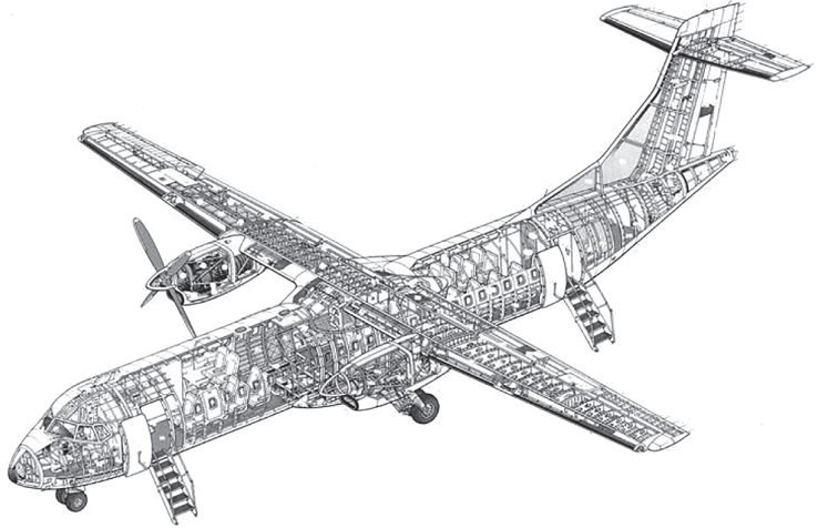
Figure 2.2 ATR 72 turboprop aircraft cutaway diagram.
2.3.3 Military Aircraft and Its Component Configurations
Table 1.3 in Section 1.9.1 compared the difference between civil and military aircraft design and operation. On account of its mission requirements military configurations are more diverse than civil designs. Figures 2.3 depicts a blowout diagram of the General Dynamics (now Boeing) F16 showing the internal structural layout.
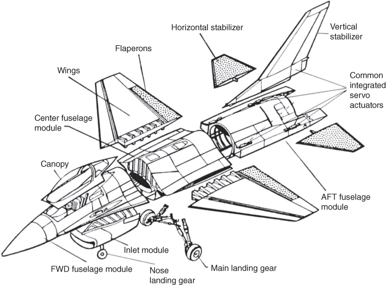
Figure 2.3 Schematic blown‐out diagram of Boeing F16 showing the internal structural layout.
Source: Courtesy of Michael Niu – [24].
Due to design differences on account of the mission role (Table 1.3), the combat aircraft structural subcomponent groups differ from the civil aircraft structural subgroups as described earlier. This is mainly evident in fuselage structure, which invariably houses the power plant (except large bombers and transport aircraft), unlike commercial civil aircraft designs. Combat aircraft structural components subsections are grouped as follows. The densely packed fuselage design typically has three subgroups as follows.
- Front‐fuselage sub‐group (Military). The front fuselage starts with the nose cone, which has to be pointed for supersonic capability, and then houses a radar that could be of around 1 m diameter. The nose cone can be swung open to access for radar maintenance. The cone section is attached to flight deck module to house the flight crew, instruments, system black boxes and so on, all requiring relatively more frequent inspection and maintenance. The nose undercarriage is attached to this section. It may or may not have the intake, depending on the design.
The military aircraft pilot seat has more freedom to recline so as to shorten carotid artery height to reduce blood starvation to the brain at high g manoeuvres that causes pilot blackouts.
- Mid‐fuselage group (Military). This is a complicated structural subgroup that bears the wing loads, air‐brake loads and the main undercarriage loads. Wing are attached to this section and it houses the main undercarriage as well as having a hollow duct for the engines. Practically all the cable, fuel and oil pipes, pneumatic ducts and linkages go through this section. Narrowing of fuselage section for area‐ruling in some designs is done. This makes military aircraft mid‐fuselage design considerably more complex compared to hollow constant cross‐section transport aircraft mid‐fuselage design considerations.
The fuselage belly fairing would house accessories; in most cases, the undercarriage. Current tendencies for the wing‐body fairing with considerable blending for superior aerodynamic considerations, for example, to improve lift to drag ratio and fly at higher angle of attack. In a blended fuselage it is hard to isolate the fuselage, possibly a convenient choice would be where the wing root is attached.
- Aft‐fuselage sub‐group. The fighter aircraft fuselage would invariably house the power. Fuselage aft ends up as engine exhaust system and therefore will not have closure as in civil design. In a case where the engine dangles below the fuselage spine (F4 Phantom), then a pointed aft end closure follows. Power plants require periodic maintenance for which the aft fuselage needs to be spilt or the mid‐fuselage to be opened to access the engine, especially if it has to be taken out.
- Lifting surfaces group (Military). In military aircraft design wing, stability and control surfaces group are dealt with together as some designs have both empennage and canard all working together for extreme manoeuvres during combat, unlike civil aircraft designs Wing. The evolution of fighter aircraft shows the dominant delta or short trapezoidal wing planform. This is for the obvious reasons of having high leading‐edge sweep; a low aspect ratio to negotiate high g manoeuvres would generate a high wing root bending moment. It could restrict span growth but encourage a large wing root chord of delta or trapezoid shape with strake planform as in the cases of the F16, F18 and so on. For control reasons, it could have additional surfaces. The following are the configuration choices (strakes are taken as part of the wing). Section 4.17 describes in detail with illustrations the following types of configurations.
- One‐surface configuration. Pure delta planform or its variation – the trailing edge of the delta like wing can be made to work like H‐tail as an integral part of the wing (Mirage 2000).
- Two‐surface configuration. Two‐surface configuration has two possibilities – tail in back or tail in front. Delta like wing or trapezoidal wing with conventional H‐tail for pitch control (MIG 21). In some designs the H‐tail is replaced by a canard surface for pitch control in relaxed stability (has destabilising effect). Two‐surface configuration with strake is shown in. Variants are double delta (SAAB Viggen).
- Three‐surface configuration. The ultimate kind is of three‐surface configuration. It has wing, H‐tail in aft end and canard in the front end (Sukhoi Su37).
- Empennage group. Combat aircraft empennage shaping and sizing is a complex procedure (Section 6.15.6), primarily on account of short tail arm and the need to fly in relaxed stability to execute fast and hard manoeuvres. The B2 apparently appears to be without a tail. The F22 has a large canted V‐tail. Options for control surface configuration are be shown along with wing options. The delta wing has an H‐tail integrated with it. This book will adhere to the conventional configuration of H‐tail and V‐tail for the trainer aircraft example. Modern designs deploy tailerons (a stabilator – see Section 16.9.1) to initiate pitch and roll control by the H‐tail.
- Intake group. Instead of pod mounted engines, military aircraft have engines embedded into the fuselage with integrated intake. Military aircraft intake design is a complex procedure as the power plant is kept within the fuselage unlike the simpler pod mounted configuration of civil aircraft. Therefore, instead of having a nacelle, air‐breathing intakes become an integral part of the fuselage.
These six groups of aircraft components offer the preliminary shape of candidate combat aircraft configurations. Eventually, after the wing sizing and engine matching exercise, the choice for configuration has to be narrowed down to one that would offer the best choice for the mission. The family derivatives of military aircraft are quite different, again depending on the mission role, for example, use of additional crew, trainer version, carrier borne version, longer range version, improved variant version and so on. Undercarriage information is dealt with separately in Chapter 9.
Military configuration study would also require some iterations to position the empennage and undercarriage with respect to the wing, as initially the centre of gravity (CG) position is not known. Weights are estimated from a provisional positioning and then the positions fine‐tuned through iterations when the CG is known. In a classroom exercise, one iteration suffices.
The role of the canard in military applications is quite different from that of the role in civil aircraft designs. It has been found that strakes can also provide additional vortex lift and fast responses to pitch control with a conventional tail. The choice for strake or canard is still not properly researched in the public domain. It is interesting to note that US designs have strakes while the European ones have a canard. A detailed study of aircraft control laws and fly‐by‐wire (FBW) system architecture is required to make the choice. Up until the 1990s, flaws in FBW software caused several serious accidents.
Wing attachment to fuselage varies from case to case. The leading edge can have slats and the trailing edge would invariably have flaps. Centrally mounted large air brakes to decelerate have practically eliminated the role of spoilers. Landing in a shorter airfield may require deployment of a brake parachute.
Since military aircraft are expected to encounter transonic flight, aircraft cross‐sectional area distribution becomes an important consideration. A seamless smooth distribution of cross‐section (area‐rule) is explained in Section 3.13.
Again, it is emphasised that this book is introductory in nature. Due to not having enough information on modern fighter design considerations, the author restricts military aircraft design exercises to a trainer class of aircraft. In this book, a military trainer in the class of Royal Air Force (RAF) Hawk is dealt with. An example of an Advanced Jet Trainer (AJT) with a Close Air Support (CAS) variant is described and worked on as a military trainer aircraft design, greatly simplifying the objective for military aircraft design. The readers will find that there is a lot to learn from this class of aircraft to have a feel for military aircraft design considerations.
2.4 Typical Aircraft Design Process
The typical aircraft design process follows the classical systems approach pattern. The official definition of a system, adopted by the International Council of Systems Engineering (INCOSE) [25] is: ‘A system is an interacting combination of elements, viewed in relation to function’. The design system has an input (i.e. a specification or requirement) that undergoes a process (i.e. phases of design) to obtain an output (i.e. certified design through substantiated aircraft performance), as shown in Figure 2.4.

Figure 2.4 Aircraft design process (see Chart 2.1).
In the following are the definitions of the terms used in Figure 2.4.
2.4.1 Input
The project identification process through year‐round market study (in consultation with potential operators) and research for the extent of advanced technologies to be adopted) to establish a new aircraft project within a company's capability to successfully compete in the market in order to grow, if not sustain. Market study presents the requirements/specification of the new aircraft presented to management to consider.
As for subsystems, the components of an aircraft are interdependent in a multidisciplinary environment, even if they have the ability to function on their own (e.g. wing‐flap deployment on the ground is inert, whereas in flight it affects vehicle motion). Individual components such as the wings, nacelle, undercarriage, fuel system and air‐conditioning also can be viewed as subsystems. Components are supplied for structural and system testing in conformance with airworthiness requirements in practice. Close contact is maintained with the planning engineering department to ensure that production costs are minimised, the schedule is maintained and build tolerances are consistent with design requirements.
Chart 2.1 suggests a generalised functional envelope of aircraft design architecture as a system, which is in line with the Aircraft Transport Association (ATA) index [26] for commercial transport aircraft. Further descriptions of subsystems are provided in subsequent chapters.

Extensive wind tunnel, structure and aircraft systems testing are required early in the design cycle to ensure that safe flight tests result in airworthiness certification approval. The multidisciplinary systems approach to aircraft design is carried out within the context of integrated product and process development (IPPD). Four phases comprise the generic methodology (discussed in the next section) for a new aircraft to be conceived, designed, built and certified.
Civil aircraft projects usually proceed to preproduction aircraft that will be flight‐tested and sold, whereas military aircraft projects proceed with technical demonstrations of prototypes (technology demonstrator) before the go‐ahead is given. The technologies demonstrators are typically scaled down aircraft meant to substantiate cutting‐edge technologies and are not sold for operational use.
2.5 Market Survey – Project Identification
A very important part of manufacturers is connecting their capabilities to customers, more so for capital intensive product like aircraft. Market survey plays a central role as a communication tool.
Typically, market survey and analyses are carried out by a separate marketing group, which may be outside the aircraft design bureau but stays in close interaction to arrive at a product line to be considered by management as a candidate project to be undertaken. The marketing group stays in touch with potential customers (e.g. airline operators) and tries to harmonise diverse requirements to consolidate a product in a family concept of designs catering for a wide range of demand. This chapter attempts to introduce to the readers what is expected from the design engineers. It is recommended that class may conduct a mock market survey to arrive at a project to be undertaken as a classroom exercise.
In a free market economy, an industry cannot survive unless it grows. In a cost intensive civil‐market economy, governmental sustenance is only a temporary relief. The starting point to initiate a new aircraft design project is to establish the key drivers – that is, the requirements and objectives based on market, technical, certification and organisational requirements. These key drivers are systematically analysed and then documented by aircraft manufacturers (Chart 2.2).

Chart 2.2 The design drivers (in the free market economy, a design has to face competition).
Documents, in several volumes, describing details of the next layer of design specifications (requirements), are issued to those organisations involved with the project. Market survey is a way to determine customer requirements; user feedback guides the product. In parallel, the manufacturers incorporate the latest but proven technologies to improve design to stay ahead of the competition, always confined within the financial viability of what the market can afford. Dialogue between manufacturers and operators continues all the time to bring out the best in the design.
Military product development has a similar approach but would require some modifications to Chart 2.2. Here, the government is both the single customer and the regulatory body. Therefore, competition is only between the bidding manufacturers. The market is replaced by operational requirements arising from perceived threats from potential adversaries. Column 1 of Chart 2.2 then becomes ‘operational drivers’ that include weapons management, counter intelligence and so on. Hence, this section on market survey is divided into civil and military customers as shown in Chart 2.3. ‘Customer’ is a broad based term and is defined in this book in the manner given in the chart.

Chart 2.3 Customers of an aircraft manufacturer.
In the UK military, the Ministry of Defence (MoD), as the single customer, searches for a product and circulates a Request for Proposal (RFP) to the national infrastructure, where most manufacturing is run privately. It is similar in the United States, but using a different terminology. The product search is a complex process – the MoD must know a potential adversary's existing and future capabilities and administrate national research, design and development (RD&D) infrastructures to be ready with discoveries and innovations to supersede an adversary's capabilities.
The air staff target (AST) is an elaborate aircraft specification as a customer requirement. A military project is of national interest and, in today's practice, capable companies are invited to first produce a technology demonstrator as proof of concept. The loser in the competition is paid by the government for the technology demonstrator aircraft and learns about advanced technology for the next RFP or civilian design. Therefore, in a sense, there is no loser and the nation hones its technical manpower.
Although it is used, the authors do not think an ‘RFP’ is appropriate terminology in civilian applications: Who is making the request? It is important for aircraft manufacturers to know the requirements of many operators and supply a product that meets the market's demands in performance, cost and time frame. Airline, cargo and private operators are direct customers of aircraft manufacturers, which do not have direct contact with the next level of customers (i.e. passengers and cargo handlers – see Chart 2.3). Airlines do their market surveys of passenger and freight requirements and relay the information to manufacturers. The surveys often are established by extensive studies of target‐city pairs, current market coverage, growth trends and passenger input. Inherent in the feedback are diverse requirements that must be coalesced into a marketable product. A major order from a single operator could start a project, but manufacturers must cater to many operators to enlarge and stabilise their market share. The civilian market is searched through a multitude of queries to various operators (i.e. airlines), both nationally and internationally. In civil aviation, the development of the national infrastructure must be coordinated with aircraft manufacturers and operators to ensure national growth. Airlines generate revenue by carrying passengers and freight, which provide the cash flow that supports the maintenance and development of the civil aviation infrastructure. Cargo generates important revenues for airlines and airports and the market for it should not be underestimated – even if it means modifying older aeroplanes. Manufacturers and operators are in continual contact to develop product lines with new and/or modified aircraft. Aircraft manufacturers must harmonise the diversity in requirements such that management decides to undertake a conceptual study to obtain the go‐ahead. There is nothing comparable to the process taken by the MoD to initiate an RFP with a single customer demand.
The private or executive aircraft market is driven by operators that are closely connected to business interests and cover a wide spectrum of types, varying from four passengers to specially modified midsized jets.
In its lifespan, military aircraft utilisation in peacetime is approximately 7500 hours, about one‐tenth that of commercial transport aircraft (i.e. ≈75 000 hours). Annual peacetime military aircraft utilisation is low (i.e. ≈600 h yr−1) compared to annual civil aircraft utilisation, which can exceed 3000 h yr−1. Although derived from the same scientific basis, the aircraft design philosophy for the military and civil aircraft differs on account of their mission role (see Section 1.9.1, Table 1.3).
2.5.1 Civil Aircraft Market – Product Identification
Following up on the review in Chapter 1 about the current status of the civil aircraft market, this section describes how to generate aircraft specifications that will help to sell the product and generate a profit. The coursework starts here with a mock (i.e. representative) market survey leading to what must be designed – that is, the conception of the aircraft, the Phase I obligations.
Input from operators to manufacturers is significant and varied. The manufacturer needs to group the requirements intelligently in a family of aircraft sizes and capabilities. It is necessary to cover as much ground as the market demands, yet maintain component commonalities in order to lower development costs of the derivative aircraft in the family. This book lists only those market parameters that affect aircraft aerodynamic design, the most important being the payload‐range capability of the aircraft, which has the greatest influence in shaping the aircraft. Details of other requirements (e.g. systems requirements, maintenance and passenger services) are not discussed here but are briefly introduced.
For the mock market studies, students may be asked to table aircraft requirements as if they are representing the airlines' interest. It is understandable that they may list requirements that are not practicable. It is therefore the instructor's responsibility to provide reasons for discarding each impracticable point and then coalescing the remainder into a starting point. Section 2.8 suggests interesting cases for coursework experience. There is a wide variety of civil aircraft in operation; in the following are the requirements for the three classes addressed in the scope of this book.
There are various models of new aircraft design process published in public domain, most of them suggested by researchers/academics. Unfortunately, the methodologies adopted in industry are not readily available. While the published materials offer some insight, the question remains on how effective the suggested research publications are in the aircraft industries.
During the early 1970s, the Japanese innovative management practices known as the Quality Function Deployment (QFD) [27] showed remarkable success in manufacturing process to become world leaders in bringing out quality products that made enormous gains in their export market. During the 1980s, the USA made extensive studies on the Japanese approach and presented an approach road with a tool known as the House of Quality (HOQ) [28] that can be applied in the western environment.
The HOQ is a management tool applied at the conceptual stages of product development that maps attributes of the parameters, cascading down the phases of design. The method brings out the perceived importance of various parameters to set targets for design. The HOQ presents a series of matrices in diagram form called a House of Quality on account of having a roof‐like structure in its top. This house can be divided in ‘rooms’, representing the attributes to consider, for example, design requirements, their relative importance, customer feedback and so on. The method demonstrated improvements for the organisations those who are in the consumer market, where customers are the general public and the manufacturers bring out products perceived as having customer appeal backed up by aggressive advertisement.
However, the aerospace market differs from the consumer market. There are limitations in applying the QFD/HOQ method in high‐technology with very high investment and with low production volume of high cost aerospace products. The main customers in aerospace industries are the (airline) operators and general public feedback to manufacturing industries comes through operators. The (airline) operators have in‐house engineers, some with design experience from industries and are knowledgeable about their requirements. Aircraft manufacturers are in constant dialogue with the operators to explore what kind of new advanced technologies can be introduced to stay ahead of competition, these serving as the drivers to lay down the new aircraft specifications meeting the mission requirements, not overlooking public opinion. Here, the HOQ analyses may prove useful by the marketing department of aircraft manufacturers to incorporate some of the user requests. Military aircraft design office starts with the specifications laid by the MoD in their RFP. A technology demonstrator will refine the advanced technology to be incorporated in the new design.
The aircraft design office is supplied by the new aircraft project requirements/specifications. It is suggested that a mock survey in a classroom exercise may avoid HOQ analyses. Once specifications are finalised, the search is constrained with little scope for the aircraft design bureau to apply the QFD/HOQ tool. Each requirement is of importance in the competitive high investment endeavours, setting relative importance may be counterproductive in a fiercely competitive environment. Industry management may take an interest in QFD/HOQ, primarily aimed at production planning but the design office have their set procedure developed over time. It is for this reason that this book bypasses dealing with QFD/HOQ in new aircraft project design phases as described in Section 2.6. (Applying QFD/HOQ in aircraft design phases may have limitations but it is by no means a flawed system as the consumer market has shown uniform gains by adopting it. Readers are recommended to explore related publications in the public domain [27, 28].)
After the market demand and manufacturer's capabilities are established, the new aircraft design starts to progress with the following considerations.
- Candidates' aircraft configurations are presented for management review to cater for the diverse range customer requirements that can be combined into a family of designs retaining component commonality as a cost reduction measure, each variant catering for the needs of the customer for their mission requirements. The technology level to be adopted in all areas of the project has to be established, both for design and manufacture.
- The most suited configuration from the candidates' designs is taken up with a view towards obtaining the go‐ahead for the project. After the go‐ahead, it then goes through detailed analyses to ensure aircraft performance, handling criteria, structural and systems integrity complying with airworthiness standards. A family of variant designs are also offered to cover the wider market at a lower cost.
- Establish the human interface for both the crew and customer for ease of operation of the bought‐out items offering best value for money as well as being low weight.
- Management strategies to keep cost low and remain competitive. Efforts are made to make the product right first time at every stage of progress. Extensive risk analyses are made.
- Establish the manufacturing philosophy and ensure quality.
- Ensure maintainability, training, support for customers and disposal at the end of aircraft life.
2.6 Four Phases of Aircraft Design
Given next are the generic details of the new aircraft design process, in four phases. At the end of the standalone Phase I of the new aircraft project devoted to conceptual study, after the approval to go‐ahead is obtained, the project enters the ‘point of no return’. The next three phases run continuously without any marked delineation, the beginning of next stage overlapping the end of the previous. Industrial practices may vary from company to company but the underlying theme is nearly the same, as given in the next section.
- Concept design phase (Phase I). This is the project definition and project finalisation phase, conducted by a small number of experienced engineers in a dedicated group to quickly present a viable aircraft configuration and performance capabilities at a credible accuracy level, sufficient to guarantee the operators what to expect, to the management to decide to give a go‐ahead or not. Naturally, budget allocation at this stage is kept low due to the uncertainty in advancing the project. This is the subject matter of this book.
- Design analyses. This consists of two phases (Phases II and III) as described next.
- Project Development Phase (Preliminary Design) – Phase II This starts after go‐ahead for the new aircraft project is obtained when management commits with extended budgetary provision to make detailed analyses. The project is now committed as a point of no return with an expectation of an investment return. This has two stages as follows. In this phase, the prediction of aircraft capability is fine‐tuned to high accuracy with detailed computer‐aided engineering (CAE) analyses and extensive aerodynamic, structure and system tests. Detailed structural design starts now (details in Sections 2.6 and 2.7).
- Detailed Design Phase (Full‐Scale Product Development) – Phase III
In this phase, for civil aviation, the preproduction or prototype, and for combat aircraft scaled down technology demonstrator building, is accelerated (details in Sections 2.6 and 2.7).
- Certification/verification (Phase IV). This is the final phase to get preproduction fight tested and certified for operation (details in Sections 2.6 and 2.7).
Aircraft manufacturers conduct year‐round exploratory work on research, design and technology development as well as market analysis to search for a product. A new project is formally initiated in the four phases shown in Chart 2.4, which is applicable for both civil and military projects.

Chart 2.4 Four phases of the aircraft design and development process.
Among organisations, the terminology of the phases varies. Chart 2.4 offers a typical, generic pattern prevailing in the industry. The differences among terminologies are trivial because the task breakdown covered in various phases is approximately the same. For example, some may see the market study, specifications and requirements as Phase I and the conceptual study as Phase II; others may define the project definition phase (Phase II) and detailed design phase (Phase III) as the preliminary design and full‐scale development phases, respectively. Some prefer to invest early in the risk analysis in Phase I to get more information and delay go‐ahead; however, the general trend is to make risk analyses in Phase II when the design is better defined, thereby saving the Phase I budgetary provisions in case the project fails to obtain the go‐ahead. A military programme may require early risk analysis because it would be incorporating technologies not yet proven in operation. Some may define disposal of aircraft at the end as a design phase of a project.
Adhering to the general pattern, companies conduct the design phases as evolved over time and became ingrained to their practices. It is for this reason, the topic is not elaborated on any further. A new employee should be able to sense the pulse of organisational strategies and practices as soon joining a company.
Company management establishes a dedicated Design‐Build‐Team (DBT) to meet at regular intervals to conduct design reviews and make decisions on the best compromises through multidisciplinary analyses (MDA) and multidisciplinary optimisation (MDO), as shown in Chart 2.5; this is what is meant by an IPPD (i.e. concurrent engineering) environment.
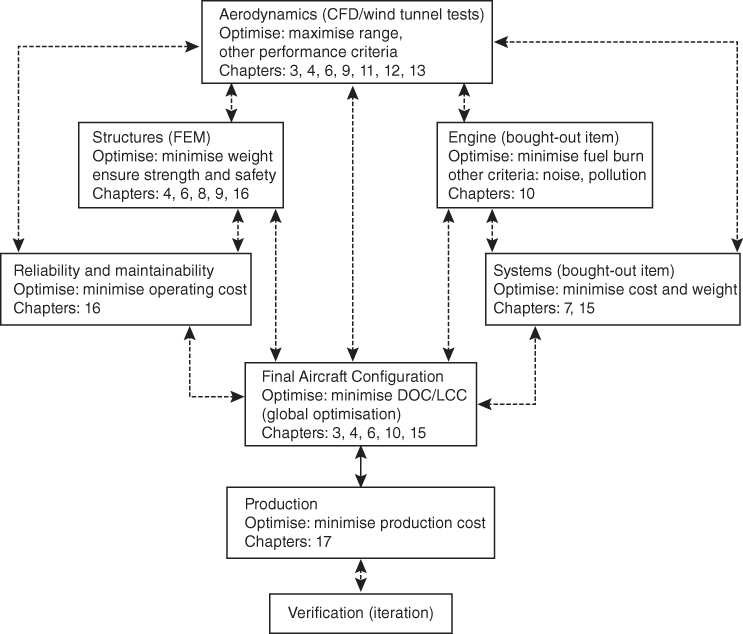
Chart 2.5 Multidisciplinary analysis (MDA) and optimisation (MDO) flow chart.
The conceptual phase of aircraft design is now conducted using a multidisciplinary approach (i.e. concurrent engineering), which must include manufacturing engineering and an appreciation for the cost implications of early decisions in IPPD environment. As mentioned in Chapter 1, the chief designer's role has changed from telling to listening; he or she synthesises information and takes full command if and when differences of opinion arise. Margins of error have shrunk to the so‐called zero tolerance so that tasks are done right the first time; the Six‐Sigma approach is one management tool used to achieve this end.
2.6.1 Understanding Optimisation
Specialist areas may optimise design goals, but in an IPPD environment, compromise must be sought. It is emphasised frequently that optimisation of individual goals through separate design considerations may prove counterproductive and usually prevents the overall (i.e. global) optimisation of ownership cost. MDO offers good potential but it is not easy to obtain global optimisation; it is still evolving. In a way, global MDO involving many variables is still an academic pursuit. Industries are in a position to use sophisticated algorithms in some proven areas. An example is reducing manufacturing costs by reshaping component geometry as a compromise – such as minimising complex component curvature. The compromises are evident in offering a family of variant aircraft because none of the individuals in the family is optimised, whereas together, they offer the best value. In other words the aim is to have a ‘satisfied’ rather than an ‘optimised’ design.
Industry is aware of the importance of optimisation but in the design practice, simple parametric optimisation taking one variable at a time yields a satisfactory result. It is for this reason this book does not deal with any optimisation process unless it is supported by worked‐out examples substantiated with existing designs.
2.6.2 Typical Resources Deployment
All phases do not work under uniform manpower loading; naturally, Phase I starts with light manpower during the conceptual study and reaches peak manpower (100%) at Phase III; it decreases again when flight testing starts, by then the design work is virtually done and support work continues.
Figure 2.5 is a typical distribution of cost and manpower loading (an average percentage is shown); the manpower loading forecast must be finalised during the Phase I study. The figure also shows the cumulative deployment. At the end of a project, it is expected that the actual figure should be close to the projected figure. Project costs consist primarily of salaries (most of the cost), bought‐out items, and relatively smaller miscellaneous amounts (e.g. advertising, travel and logistics). Chain lines in Figure 2.5 illustrate the cost‐frame outlay.
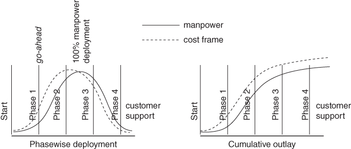
Figure 2.5 Resource deployments (manpower and finance).
2.6.3 Typical Cost Frame
A crude development cost, up to certification (in the year 2015 in US Dollars), is shown in Table 2.1. Typical unit aircraft costs by class are also given (there is variation among companies). A substantial part of the budget is committed to Phase I.
Table 2.1 Development costs up to certification included (cost at 2015 prices).
| Aircraft class (turbofan) | Development cost (US$a) ) | Unit cost (US$* ) |
| 6‐passenger general aviation aircraft | 7–12 million | ≈±2 million |
| 10‐passenger business aircraft | 25–40 million | 5–10 million |
| 50‐passenger regional aircraft | 60–100 million | 25–30 million |
| 150‐passenger midsized aircraft | 200–500 million | 50–70 million |
| 500+ ‐ passenger large aircraft | 2–10 billion? | 200–300 million |
| Military combat aircraft (high end) | 5–15 billion? | 100+ million? |
aDoes not include production launch cost.
2.6.4 Typical Time Frame
Typical time frames for the phases of different types of projects are shown in Chart 2.6. All figures are the approximate number of months. Exploratory work continues year‐round to examine the viability of incorporating new technologies and to push the boundaries of company capabilities – which is implied rather than explicit in Chart 2.6.

Chart 2.6 Typical project time frame.
When an aircraft has been delivered to the operators (i.e. customers), a manufacturer is not free from obligation. Manufacturers continue to provide support with maintenance, design improvements and attention to operational queries until the end of an aircraft's life. Modern designs are expected to last for three to four decades of operation. Manufacturers may even face litigation if customers find cause to sue. Compensation payments have crippled some well‐known general aviation (GA) companies. Fortunately, the 1990s saw a relaxation of litigation laws in GA for a certain period after a design is established, a manufacturer's liabilities are reduced; this resulted in a revitalisation of the GA market. Military programmes involve support from ‘cradle to grave’.
This emphasises that the product must be done right the first time. Midcourse changes add unnecessary costs that could be detrimental to a project – a major change may not prove sustainable. Procedural methodologies such as the Six‐Sigma approach have been devised to ensure that changes are minimised.
2.7 Typical Task Breakdown in Each Phase
Typical task obligations in each phase of civil aircraft design are defined in this section. Military aircraft designs follow the same pattern but more rigorously. Military aircraft must deal with new technologies, which could still require operational proving; therefore, there is uncertainty involved in military aircraft projects.
- Phase I: Conceptual Study Phase (Feasibility Study)
Much of the work in the conceptual study phase can be streamlined through a good market study to identify a product line within a company's capabilities. In this phase, findings of the market study are developed with candidate configurations; the technology to be adopted is firmed up and the economic viability is finalised. This is accomplished through aircraft sizing, engine matching, preliminary weight estimation, and evolution of a family of aircraft with payload and range combinations (i.e. aircraft performance) for all configurations. Planning portfolios with budgetary provisions, manpower requirements, progress milestones, potential subcontract/risk‐sharing partners' inputs and so forth are included as the starting point of the design process. In general, at the end of this phase, management decision for a go‐ahead is expected with a final configuration selected from the candidate configurations offered. Continuous interaction with potential customers (i.e. operators and subcontractors) occurs during this phase, with the objective of arriving at a family of aircraft as the most ‘satisfying’ design with compromises rather than an ‘optimum’ solution. Management may request a level of detail (e.g. risk analysis) that could extend the study phase or flow into the next phase, thereby delaying the go‐ahead decision to the early part of Phase II. This is likely if the candidate aircraft configurations are short‐listed instead of finalised. For those designers who have planned ahead, Phase I should finish early – especially if they are well versed in the product type and have other successful designs in their experience.
- Phase II: Project Definition Phase (Preliminary Design)
This phase begins after the go‐ahead has been given to a project, and a ‘point of no return’ is reached during this phase. Project definition sometimes may overlap with the detailed design phase (i.e. Phase III). During the advanced design phase, the project moves towards a finer definition, with a guarantee that the aircraft capabilities will meet if not exceed the specifications. Some iteration invariably takes place to fine‐tune the product. Details of the technology level to be used and manufacturing planning are essential, and partnership outsourcing is initiated in this phase. Procurement cost reviews and updates also are ongoing to ensure that project viability is maintained. Many fine aircraft projects have been stalled for lack of proper planning and financial risk management. The beginning of metal cutting and parts fabrication as well as deliveries of bought‐out items (e.g. engine and avionics) must be completed in Phase II. In this phase, extensive wind tunnel testing, CFD analysis, detailed weights estimation, detailed structural layout and finite element method (FEM) analysis, system definitions, production planning and so forth are carried out. (Readers may study recent case histories of products such as the Swearingen SJ30 [now certified and under production] and the Fairchild–Dornier 928.)
- Phase III: Detailed Design Phase (Full‐Scale Product Development)
In this phase, manufacturers push towards completion – when peak manpower is deployed for the project. Normally, projects cannot sustain delay – time is money. All aspects of detailed design and systems architecture testing are completed in this phase. (The test rig is called an ‘iron bird’ – it simulates full‐scale control and system performance.) At the end of Phase III, the aircraft assembly should near, if not achieve, completion.
- Phase IV: Final Phase (Certification)
Phase IV must start with completion of the aircraft assembly for ground‐testing of installed systems and other mandatory structural strength‐testing to prepare for flight testing. In general, two to four aircraft are needed to complete nearly 200–800 flight testing sorties (depending on the type of aircraft) towards substantiation for certification of the airworthiness standard. At this stage, there should be no major setbacks because the engineers have learned and practised aircraft design well with minimal errors.
Each project has a characteristic timeline; this book uses a four‐year project time. Remember, however, that some projects have taken more or less time. Section 2.4.2 is a detailed breakdown of a small aircraft project for a small or medium company. The authors recommend that similar detailed milestone charts be drawn for coursework projects to give an idea of the manpower requirements.
2.7.1 Functional Tasks During Conceptual Study (Phase I)
Because this book is concerned only with Phase I, it is important to delineate functional task obligations assigned to individual designers – also known as top‐level definition. Market specifications should first be delineated to develop task content, as shown in Chart 2.5, for the top‐level study of civil aircraft during Phase I. Payload determines the fuselage size and shape and leads into undercarriage design, depending on wing and engine positioning. Wing design largely determines the range, operational envelope and field‐performance objectives. Considering all requirements together, the aircraft configuration evolves: there can be more than one candidate configuration (e.g. high or low wing, nacelle location and empennage arrangement). Chart 2.7 can be divided into functional work group activity to focus attention on specific areas – necessarily in an IPPD environment for MDA.
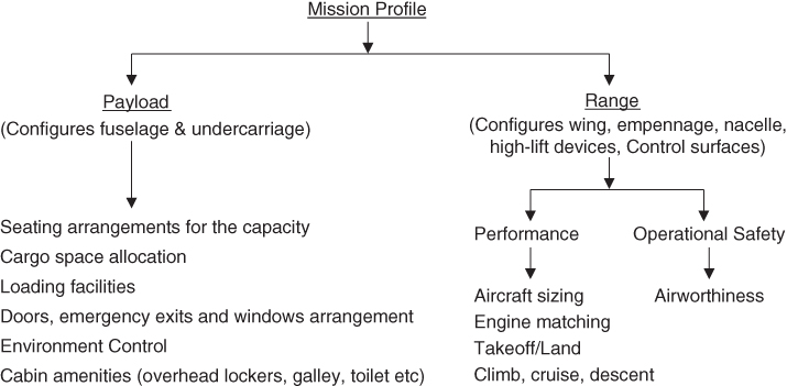
Chart 2.7 Top level definition (Phase I, conceptual study).
The military aircraft design approach is not significantly different except that the payload is the armament, which is generally under‐slung or kept inside the fuselage bay. The mission profile is the sortie profile for the military role meeting the target range with the capabilities to return to base.
2.7.2 Project Activities for Small Aircraft Design
Progress monitoring is essential to keep an aircraft design project on schedule and within the budgetary provisions. To monitor progress, milestones are laid down in as much detailed work breakdown as possible as soon as the go‐ahead is obtained. There are several ways to depict the work breakdown showing completion dates, all are nearly similar and the choice depends on the preferences of the manufacturer. By far the most popular and widely practised depiction is in the form bar chart known as Gantt chart. This lists activities and check points in convenient details corresponding to the planned time frame. The activities are listed next, phase‐wise.
The project DBT meets regularly in an IPPD environment to monitor progress and streamline the way if any bottle‐neck is envisaged. For any critical obstacle, the DBT meets as and when required to remove it. Cash flow and bought‐out supply do not show in a Gantt chart, and finance and purchase departments are kept in the monitoring loop and have their own progress monitoring chart made to their convenience, which may not be in the form of a Gantt chart. In fact, all departments work together to achieve the goal to make the project a success.
Table 2.2 gives a schematic bar chart (Gantt chart), in short, of these tasks just to give an example. The readers are required to make a detailed Gantt chart, expanding all tasks to segmented detail to keep track on progress. Any bottlenecks must be foreseen by the respective line managers and corrective measures taken. Once again it is stressed that all drawings are made in CAD.
Table 2.2 Gantt chart for the activities of the small aircraft project. Figures in parentheses are the time frames in months.
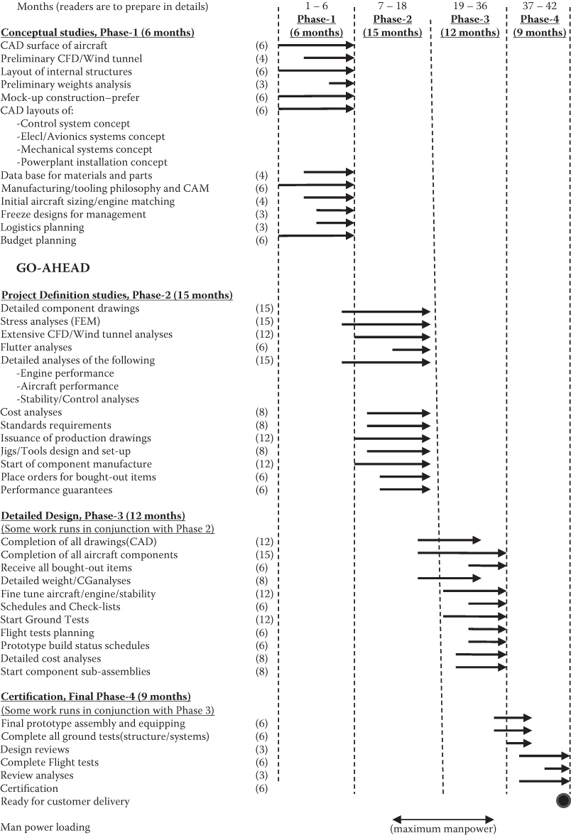 |
Typical work content and milestones for a small aircraft project are given here in blocks of time; readers need to expand this in bar chart form (the coursework involved in drawing the Gantt chart may alter the contents of the table, as required). Larger aircraft design follows similar activities in an expanded scale suited to task obligations.
Phase 1 Conceptual Design – 6 months
- Market Survey – establish aircraft specification from customer requirements. Information is extracted from year‐round exploratory work.
- Layout candidate aircraft configurations with the fuselage, then wing, empennage (canard if considered), undercarriage, power plant and so on.
- Establish wing parameters as the most important component in synthesising aircraft. Select the aerofoil profile, its thickness to chord ratio, wing reference and planform areas, aspect ratio, wing sweep, taper ratio, wing twist, spar location, flap area, flight control and wing location with respect to the fuselage. The same considerations apply to all other lifting areas.
- Initiation of computer‐aided drawing (CAD) 3D surface modelling.
- Preliminary CFD analysis to establish pressure distribution and loads on aircraft.
- May conduct some preliminary wind tunnel tests.
- Preliminary weights and CG estimates.
- Aircraft preliminary drag estimate.
- Size aircraft and match engine.
- Establish engine data.
- Preliminary aircraft and engine performance.
- Freeze configuration to one aircraft along with a family of aircraft if considered.
- Layout of internal structures and arrangement of fuselage interior.
- Mock‐up drawings, construction and initial evaluation.
- Control system concept layout in CAD.
- Electrical/avionics systems concept layout in CAD.
- Mechanical systems concept layout in CAD.
- Power plant installation concept in CAD.
- Data base for materials and parts.
- Plan for bought‐out items and delivery schedule.
- Planning for outsourcing, if any.
- Preliminary cost projection.
Obtain management go‐ahead
Phase II: Project Definition – 9 months
Integrated and component drawings in CAD.- FEM stress analysis of all components – wing, fuselage and so on.
- Completion of mock‐up and final assessment.
- Advanced CFD analysis.
- Wind tunnel model testing and CFD substantiation.
- Flutter analysis.
- Extensive and final aircraft and engine performance.
- Detailed part design and issuance of manufacturing/production drawings in CAD.
- Aircraft stability and control analysis and control surface sizing.
- Finalise the control system design in CAD.
- Finalise electrical/avionics systems design in CAD.
- Finalise mechanical systems design in CAD.
- Finalise power plant installation design in CAD.
- Jigs and tool design.
- Subcontracting, if any.
- Place order for bought‐out items and start receiving items.
- Cost analysis.
- Design review.
- Continue with customer dialogue and updating (no change of specification).
Phase III: Detailed Design (Product Development) Phase – 12 months
- Completion of detailed component design in CAD.
- Completion of stress analysis.
- Completion of CFD analysis.
- Revise to final weights analysis.
- Completion and issuance of all production drawings in CAD/computer aided manufacture (CAM).
- Completion of production jigs and tools.
- Parts manufacture and start of aircraft component subassembly.
- All bought‐out items received.
- Standards, schedules and check lists.
- Finalise ground/flight test schedules.
- Prototype shop status schedules.
- Revise cost analysis.
- Start of ground tests.
- Design review.
- Continue with customer dialogue and updating (no change of specification).
Phase IV (Testing and Certification Phase) – 9 months
- Final assembly and prototype equipping.
- Completion of ground and flight tests and their analysis.
- Review of analysis and, if required, modify design (aim to get it right first time).
- Overall design review.
- Review cost estimate.
- Customer dialogue and sales arrangement.
- Continue design review and support.
Note that production launch costs are normally kept separate from design and development costs. Total time to complete the project is three years (2½ from go‐ahead). The time is tight but possible. It can be stretched to a four‐year development programme for companies with limited resources.
2.8 Aircraft Specifications for Three Civil Aircraft Case Studies
It is recommended that the introductory coursework exercise uses one of the three specifications provided as a starting point. Accordingly, the initial follow‐up activity is limited to work on the Learjet 45 class aircraft (see the second design specification).
- Design Specifications of a Four‐Seater Piston Engine Aircraft as a Baseline (Federal Aviation Regulation (FAR) 23)
| Payload | 4 passengers (including pilot) + baggage (e.g. two golf bags) = 4 × 85 (averaged) + 60 = 400 kg |
| Range | 800 miles + reserve |
| Maximum cruise speed | Above 200 mph |
| Cruise altitude | Unpressurised cabin; approximately 10 000 ft (ceiling could be higher) |
| Takeoff distance | 500 m @ sea level to 35 ft |
| Landing distance | 500 m (at takeoff weight) @ sea level from 50 ft |
| Initial rate of climb | 8 metres per second (m s−1) |
| Undercarriage | Retractable |
| Cabin comfort | Cabin heating, side‐by‐side seating, cabin interior width = 50 in. |
| Technology level | Conventional |
| Power plant | Piston engine |
- Derivative Version: A Lighter Two‐Seater Light Club Trainer/Usage Aircraft (FAR 23).
- (Derivatives are more difficult to develop for smaller aircraft because there is less room with which to work. Fuselage unplugging is difficult unless the baseline design made provision for it. There are considerable savings in certification cost.)
| Payload | 2 passengers plus light baggage = 200 kg |
| Range | 400 miles + reserve |
| Maximum cruise speed | 140 mph |
| Takeoff distance | 300 m @ sea level to 35 ft |
| Landing distance | 300 m (at takeoff weight) @ sea level from 50 ft |
| Initial rate of climb | 5 m s−1 |
| Undercarriage | Fixed |
| Cabin comfort | Cabin heating, side‐by‐side seating, cabin interior width = 46 in. |
(The other specifications are the same as in the baseline four‐seater design.)
Derivative versions are achieved by shortening the wing root and empennage tips, unplugging the fuselage section (which is difficult if it is not a continuous section but is possible if the design of the baseline four‐passenger aircraft considers this in advance), lightening the structural members, re‐engineering to lower the power and so forth.
- Design Specifications of a Baseline 8–10‐Passenger (Learjet 45 Class) Aircraft (FAR 25).
| Payload | 8–10 passengers and 2 pilots + baggage |
| High comfort level | 8 × 100 (averaged) + 300 = 1100 kg |
| Medium comfort level | 10 × 80 (averaged) + 300 = 1100 kg |
| Range | 2000 miles + reserve |
| Maximum cruise speed | Mach 0.7 |
| Cruise altitude | Above 40 000 ft (ceiling over 50 000 ft) |
| Takeoff distance | 1000 m @ sea level to 15 m |
| Landing distance | 1000 m (at takeoff weight) @ sea level from 15 m |
| Initial rate of climb | 16 m s−1 |
| Undercarriage | Retractable |
| Cabin Comfort | Pressurised cabin with air‐conditioning and oxygen supply |
| Cabin interior width | =58 in. |
| Technology level | Advanced |
| Power plant | Turbofan engine |
- Shortened Derivative Version: Four To Six Passengers In a Baseline Aircraft Family (Far 25).
- (This derivative works by unplugging continuous‐section fuselage barrel on both sides of the wing.)
| Payload | 4–6 passengers and 2 pilots + baggage |
| High comfort level | 4 × 100 (averaged) + 200 = 600 kg |
| Medium comfort level | 6 × (averaged) + 120 = 600 kg |
| Range | 2000 miles + reserve |
| Maximum cruise speed | Mach 0.7 |
| Cruise altitude | Above 40 000 ft (ceiling over 50 000 ft) |
| Takeoff distance | 800 m @ sea level to 15 m |
| Landing distance | 800 m (at takeoff weight) @ sea level from 15 m |
(The other specifications are the same as in the baseline design.)
- Lengthened Derivative Version: 12–14 Passengers In the Baseline Aircraft Family (Far 25). (The longer derivative works in the same way by inserting continuous‐section fuselage plugs on both sides of the wing.)
| Payload | 12–14 passengers and 2 pilots + baggage |
| High comfort level | 12 × 100 (averaged) + 300 = 1500 kg |
| Medium comfort level | 14 × 80 (averaged) + 380 = 1500 kg |
| Range | 2000 miles + reserve |
| Takeoff distance | 1200 m @ sea level to 15 m |
| Landing distance | 1200 m (at takeoff weight) @ sea level from 15 m |
(The other specifications are the same as in the baseline design.)
- Design Specifications of a Baseline 150‐Passenger (Airbus 320 Class) Aircraft (FAR 25)
| Payload | 150 passengers = 90 × 150 = 14 500 kg |
| Range | 2800 nm (nautical miles) + reserve |
| Crew | 2 pilots + 5 attendants |
| Maximum cruise speed | 0.75 Mach |
| Cruise altitude | Above 30 000 ft (ceiling over 40 000 ft) |
| Takeoff distance | 2000 m @ sea level to 15 m |
| Landing distance | 2000 m (at 95% takeoff weight) @ sea level from 15 m |
| Initial rate of climb | 14 m s−1 |
| Undercarriage | Retractable |
| Cabin comfort | Pressurised cabin with air‐conditioning and oxygen supply, |
| Cabin interior diameter | =144 in. |
| Technology level | Advanced |
| Power plant | Turbofan engine |
- Derivative version in the aircraft family (typically Airbus 319 and Airbus 321 class on both sides of the baseline Airbus 320 aircraft). This is accomplished by plugging and unplugging the fuselage as in a Bizjet design. Readers are referred to Jane's All the World's Aircraft for derivative details and Appendix D for an example. Wide‐body aircraft design follows the methodology.
(Note: The author encourages readers to explore market surveys for other classes of aircraft. To diversify, in the following are brief specifications for two interesting examples [17]).
- Agriculture Applications Aircraft
- Airframe must be highly corrosion resistant.
- Airframe must be easily cleaned (i.e. removable side panels).
- Airframe must be flushed with water after last flight.
- Airframe must be easily inspected.
- Airframe must be easily repaired.
- Airframe must be highly damage tolerant.
- Dry and wet chemicals must be loaded easily and quickly.
- Cockpit must have excellent pilot crash protection.
- Pilot must have excellent visibility (i.e. flagman, ground crew and obstacles).
- The stall speed must be 60 knots or less.
- The service ceiling is 15 000 ft.
- Takeoff performance: 20 000‐ft field length (rough field) with 50‐ft obstacles.
- Hopper capacity: 400 US gallons/3200 lbs.
It is suggested that the design be approached through use of FAR Parts 137, 135 and 123. Readers may review current designs from Jane's All the World's Aircraft. Key considerations include choice of materials, configuration and structural layout and system design. In every other respect, the design should follow the standard approach described herein.
- Airport Adaptive Regional Transport with Secondary Role to Support US Homeland Security (Abridged from [17])
| Payload | 49 passengers + flight and cabin crew |
| Range | 1500 miles with reserve |
| Takeoff and landing | 2500 ft |
| Field length | |
| Maximum speed | 400 knots |
| Mission profile | Multiple takeoffs and landings without refuelling |
For the airport adaptive role, the aircraft can simultaneously approach a major airport in non‐interfering adverse weather and takeoff and land from shorter, largely unused runways, sub‐runways and taxiways. The aircraft will be evaluated for an automatic spiral‐descending, decelerating approach in instrument meteorological conditions (IMCs) (Category 3C) conditions and be able to continue with one engine inoperative. The aircraft also has the following secondary roles:
- Serve the civil reserve fleet and be available during a homeland‐security crisis
- Serve as an ambulance
- Serve as transport firefighters to remote wilderness areas
- Serve as an emergency response vehicle for urban terrorism or a natural disaster by changing passenger‐accommodation fitment
The aircraft will have half of the payload and a 750‐mile range into makeshift landing zones of at least 1000 ft. More information is required for the specifications, but the level of technology is not within the scope of this book.
Other than drag estimation and certification regulations (e.g. noise), the supersonic transport (SST) design is similar to subsonic transport, aircraft design methodology. Supersonic drag estimation is addressed in Chapter 9.
In contrast to the civil market, the military aviation market starts with meeting the national defence requirements. The MoD organisations constantly review perceived threats and endeavour to stay ahead of the adversary. MoD floats a RFPs with ASTs. Many uncertainties are embedded in the road to an operational product. The development cost for these hi‐tech machines is high and in many cases exceeds projected appropriations. The dominant certification standards are the Milspecs (US) and Defence Standards 970 (earlier, AvP 970 – UK). These certification standards are not as similar as are the FAR and JAR (Joint Airworthiness Regulation) requirements.
2.9 Military Market – Some Typical Military Aircraft Design Specifications
In contrast to the civil market, the military aviation market starts with meeting national defence requirements. The MoD organisations constantly review perceived threats and endeavour to stay ahead of the adversary. MoD floats RFPs with AST. A lot of uncertainties are embedded in the road to an operational product. Development cost for these hi‐tech machines is high and in many cases exceed projected appropriations. The dominant certification standards are Milspecs (US) and Defence Standards 970 as before.
2.9.1 Aircraft Specifications/Requirements for Military Aircraft Case Studies
The author recommends that the introductory classroom work on military aircraft design may start with the Turboprop Trainer (TPT) aircraft followed by an AJT design specifications as given next.
- Design Specifications of an TPT – UK Def Standards
| Technology level | metal frame and with glass cockpit (EFIS) |
| Certification standard | UK Def Standards 970 |
| Basic mission | intermediate level pilot training up to jet type |
| Mission profile | small, agile for sortie profile |
| Payload | 2 80‐kg pilots and 1000‐kg armament |
| Seating | tandem |
| Normal training configuration (NTC) | clean configuration with four pylons |
| Engine | one turboprop |
| Maximum speed | 500 kmph at 15 000 ft |
| Maximum sustained speed | 400 kmph |
| Stalling speed | 130 kmph (flaps extended) |
| Service ceiling | 10 000 m |
| Initial rate of climb | 1200 m s−1 at NTC |
| Time to climb to 7 km | 10 min at NTC |
| Turn performance | 4 g at sea level (@mean weight) |
| Manoeuvre | +8 g to −4 g (fully aerobatic) |
| Roll rate | 75° s−1 at 250 knot |
| Range | 1500 km at cruise |
| Takeoff distance | 500 m at NTC to clear 15 m (sea level) |
| Landing distance | 550 m at NTC (no brake parachute – sea level) |
| Undercarriage | retractable |
| Flight deck | ejection seat, pressurised with oxygen supply |
| Cabin interior width | 28 in |
- Design Specifications (Requirements) of a Baseline AJT
| Technology level | advanced, multi‐functional display (EFIS) |
| Certification standard | UK Def Standards 970 |
| Basic mission | training in jet aircraft up to operational conversion type |
| Mission profile | small, agile (see Chapter 13) for sortie profile |
| Payload | over 1500‐kg armament (prefer 1800 kg) |
| Number of pylons | 5 |
| Crew | two 90‐kg pilots in tandem seating |
| Normal training configuration (NTC) | clean configuration with pylons only |
| Engine | one turbofan with low bypass ratio – no afterburning |
| Maximum speed | Mach 0.75 (920 kmph) |
| Maximum sustained speed | Mach 0.7 (860) kmph |
| Stalling speed | 220/180 kmph (no flaps/flaps, respectively) |
| Service ceiling | 14 000 m |
| Initial rate of climb | 40 m s−1 |
| Time to climb to 12 km | 12 minutes |
| Turn performance | 4 g at sea level (@mean weight) |
| Manoeuvre | +8 g to −4 g (fully aerobatic) |
| Roll rate | 200° s−1 |
| Range | 700 km at sea level and 1200 km at 9‐km cruise altitude |
| Endurance | 2.5 hours with reserve |
| Takeoff distance | 1100 m to clear 15 m (sea level) |
| Landing distance | 1000 m (no brake parachute – sea level) |
| Undercarriage | retractable |
| Flight deck | ejection seat, pressurised with oxygen supply |
| Cabin interior width | 30 in |
| Technology level | advanced multifunctional display |
| Structure | primary structure of metal frame; secondary structure in composite |
- Derivative version in the family of a Baseline AJT – a single‐seat CAS aircraft (all performance figures at NTC)
| Technology level | advanced, multi‐functional display (EFIS) |
| Certification standard | UK Def Standards 970 |
| Mission profile | small, agile (see Chapter 13 for sortie profile) |
| Payload | 2500‐kg armament |
| Crew | single 90‐kg pilot |
| Number of pylons | 5 |
| Engine | one turbofan with low bypass ratio |
| Maximum speed | maximum Mach 0.75 (910 kmph) level flight |
| Maximum sustained speed | 0.7 (850 kmph) |
| Stalling speed | 240/200 kmph (no flaps/flaps, respectively) |
| Service ceiling | 14 000 m |
| Initial rate of climb | 50 m s−1 |
| Time to climb to 12 km | 8 min. |
| Turn performance | 5 g at sea level (@mean weight) |
| Manoeuvre | +8 g to −4 g (fully aerobatic) |
| Roll rate | 200° s−1 |
| Range | 700 km at sea level (no drop tanks); |
| 1500 km at 9‐km cruise (with drop tank) | |
| Sortie duration | 1.5 hours (no drop tanks) with reserve |
| Takeoff distance | 1400 m to clear 15 m (sea level) |
| Landing distance | 1200 m (at landing weight, sea level – no brake parachute) |
| Undercarriage | retractable |
| Flight deck | ejection seat, pressurised with oxygen supply |
| Cabin interior width | 30 in. |
| Structure | primary structure of metal frame; secondary structures in composite |
2.10 Airworthiness Requirements
From the days of barnstorming and stunt‐flying in the 1910s, it became obvious that commercial interests had the potential to short‐circuit safety considerations. Government agencies quickly stepped in to safeguard people's security and safety without deliberately harming commercial interests. Safety standards were developed through multilateral discussions, which continue even today. Western countries developed and published thorough and systematic rules – these are in the public domain (see relevant web sites).
All aircraft design must satisfy the minimum safety standards of the countries of operation governed by their certification agencies (authorities). In the USA the certification agency is the Federal Aviation Administration (FAA) and in Europe it is the European Aviation Safety Agency (EASA), both standards have almost similar requirements and working together to harmonise to equivalent standards. This book follows the FAA standards, which is more prevalent internationally. Civil aviation is one of two major categories of flying, representing all non‐military aviation, both private and commercial. All civil aircraft must comply with FAA and satisfy their regulations (FAR) as defined for each category of aircraft design.
The authors' preference is to work with the established FAR; the pertinent FAR is cited when used in the text and examples. This book is only concerned with FAR Parts 23 (General Aviation) and 25 (scheduled airline operations and non‐scheduled air transport operations for remuneration or hire – commercial transport category) – in short, FAR23 and FAR25, respectively. FAR documentation for certification has branched out into many specialist categories. Appendix G gives more on FARs. The FAR documentations are done in an elaborate and articulate manner and for any new reader it may appear quite challenging to grasp them in a logical manner. The basic FAR requirements, as applicable to this book, are treated here. This will give some idea on how industries deal with FAR substantiation. Industries are the places where fresh engineers will be learning about the intricacies of FAR in a formal manner.
ICAO and work together with member countries to establish common standards and recommended practices for civil aviation.
GA, a sector of civil aviation, is defined as non‐military and non‐airlines sector of aviation and broadly classified into two categories as the (i) Standard Category and (ii) Special Category. Small aircraft within GA are separated into Special Category discussed in Chapter 16. GA covers a large range of activities, both commercial and non‐commercial, including flying clubs, flight training, agricultural aviation, light aircraft manufacturing and maintenance.
The Transport Category (scheduled airline operations and non‐scheduled air transport operations for remuneration or hire) has a higher level of requirements under FAR25.
2.10.1 Code of Federal Regulations (CFR) – Title 14
CFR classifies all civil aircraft into 11 categories, 10 of them under FAR23 all below 12 500 lb and one under FAR25 in a higher specification in which all transport aircraft 12 500 lb are to be certified.
2.10.1.1 FAR23
This has two main categories, (i) Standard (four types) and (ii) Special (six types) as follows.
2.10.1.2 Standard Category (Volume 1, Section 23‐3: Aeroplane Categories Dated 2011‐01‐0)
- (i) Normal category. Aeroplanes that have a seating configuration, excluding pilot seats, of nine or less, a maximum certificated takeoff weight of 12 500 pounds or less and are intended for non‐aerobatic operation.
- (ii) Utility category. Limited to aeroplanes that have a seating configuration, excluding pilot seats, of nine or less, a maximum certificated takeoff weight of 12 500 pounds or less and are intended for limited acrobatic operation. Aeroplanes certificated in the utility category may be used in any of the operations covered under paragraph (a) of this section and in limited acrobatic operations. Limited acrobatic operation includes: (i) spins (if approved for the particular type of aeroplane) and (ii) lazy eights, chandelles, steep turns or similar manoeuvres, in which the angle of bank is more than 60° but not more than 90°.
- (iii) Acrobatic category. Limited to aeroplanes that have a seating configuration, excluding pilot seats, of nine or less, a maximum certificated takeoff weight of 12 500 pounds or less and are intended for use without restrictions, other than those shown to be necessary as a result of required flight tests.
- (iv) Commuter category. Limited to propeller‐driven, multiengine aeroplanes that have a seating configuration, excluding pilot seats, of 19 or less, and a maximum certificated takeoff weight of 19 000 pounds or less. The commuter category operation is limited to any manoeuvre incident to normal flying, stalls (except whip stalls) and steep turns, in which the angle of bank is not more than 60°.
Except for the commuter category, aeroplanes may be type certificated in more than one category if the requirements of each requested category are met.
2.10.1.3 Special Category (FAR Part 1.1)
This consists of the following six categories not dealt with in the book. These are mostly small aircraft (see Chapter 16).
- (v) Light Sports Aircraft (LSA) have two sub‐divisions, Special Light‐Sport Aircraft (S‐LSA) and Experimental Light‐Sport Aircraft (E‐LSA). FAR Part 1.1.
- (vi) Experimental. These are Experimental Amateur‐Built (E‐AB) aircraft, or experimental exhibition) – also known as home built/kit built aircraft. If complied with, these can also be certified under the LSA category. The various applications in this class are as follows:
- a) An aircraft whose purpose is to test new design concept and demonstrate its airworthiness, equipment or operating techniques. It is a research and development activity. It can be used for market survey.
- b) Exhibition and air racing.
- (vii) Limited aircraft. Surplus military aircraft converted to civilian use (Experimental Exhibition category).
- (viii) Primary aircraft. Aircraft in this category are of a simple design and intended exclusively for pleasure and personal use. Although these aircraft may be available for rental and flight instruction under certain conditions, the carrying of persons or property for hire is prohibited.
- (ix) Provisional aircraft. Aircraft with a ‘provisional’ category type certificate for special operations and operating limitations.
- (x) Restricted aircraft. These include agriculture, forest/wildlife conservation, aerial surveying, patrolling, weather observation, aerial advertising and other operations specified by the administrator.
2.10.1.4 FAR25
The FAR 25 applies to Transport Category Aircraft (scheduled airline operations and non‐scheduled air transport operations for remuneration or hire.) and has higher level of requirements compared to FAR23. This maximum takeoff weight (MTOW) is over 12 500 lb for the FAR25 category of transport aircraft.
2.10.1.5 The Parts of FAR Requirements
For convenience, the airworthiness requirements to ensure the safety standards are classified by their specialised areas along with their associated allied topics into several parts as shown in the Table 2.3. As this book only deals only with FAR23 and FAR25, the table lists only the standards for these two. Each part may have several documents describing meticulously the certification requirements in legal frame to clear any ambiguity. For design substantiation, various parts may be cross‐referenced to meet the standards required. The Appendix lists the pertinent requirements used in this book.
Table 2.3 FAR categories of airworthiness standards.
| Aircraft types | General aviation | Normal | Transport |
| Aircraft | FAR Part 23 | FAR Part 23 | FAR Part 25 |
| Engine | FAR Part 33 | FAR Part 33 | FAR Part 33 |
| Propeller | FAR Part 35 | FAR Part 35 | FAR Part 35 |
| Noise | FAR Part 36 | FAR Part 36 | FAR Part 36 |
| General operations | FAR Part 91 | FAR Part 91 | FAR Part 91 |
| Agriculture | FAR Part 137 | ||
| Large commercial transport |
Not applicable |
FAR Part 121 |
Table 2.4 gives the definitions for the GA, Normal Category and Transport of Aviation.
Table 2.4 Aircraft categories.
| Aircraft types | General aviation | Normal | Transport |
| MTOW – lb | less than 12 500 | less than 12 500 | Over 12 500 |
| No. of engine | zero or more | more than one | more than one |
| Type of engine | All types | Propeller only | All types |
| Flight crew | One | Two | Two |
| Cabin crew | None | None up to 19 PAX | None up to 19 PAX |
| Maximum no. of occupants | 10 | 23 | Unrestricted |
| Maximum operating altitude | 25 000 ft | 25 000 ft | Unrestricted |
In military applications, the standards are Milspecs (US) and Defence Standard 970 (previously AvP 970) (UK); they are different in some places.
Since 2004, in the United States, new sets of airworthiness requirements came into force for light aircraft in the category LSA class (UK – Very Light Aircraft; CS‐VLA – Certification Specifications for Very Light Aeroplanes) designs and have eased certification procedures and litigation laws, rejuvenating the industry in the sector. Europe also has a similar approach but its regulations differ to an extent. Small/light aircraft and microlight types have different certification standards not discussed in this book.
With unmanned aerial vehicles (UAVs) gaining applications in civil aviation, there will be growing demand to involve the FAA to ensure safety and regulate activities. There are other classes, for example, ultralights, trikes, hang gliders, parasols, lighter than air dirigibles, helicopters and so on, which are beyond the scope of this book.
2.11 Coursework Procedures – Market Survey
The coursework task is to conduct a mock market study. The instructor divides the class into groups of four or five students who will work as a team (see the Road Map of the Book, which gives the typical allotted time). However, how the class is conducted is at the instructor's discretion. Designing a conventional civil or a military trainer aircraft is appropriate for undergraduate introductory work. In this book, a Bizjet and an AJT aircraft design are used.
- Step 1. The instructor decides which class of aircraft will be used for the design project. Each group is required to submit their ideas of the aircraft configured with assigned design considerations. Students will have input but the instructor ultimately explains why a certain aircraft is chosen.
- Step 2. The instructor discusses each suggestion, discarding the impractical and coalescing the feasible. The instructor will add anything that is missing, with explanations.
- Step 3. Each team must then submits a scaled, three‐view sketch of the proposed design. There will be differences in the various configurations. CAD is recommended.
- Step 4. The instructor discusses each configuration, tailoring the shape, with explanation, to a workable shape. Each team works on its revised configuration; preferably, the class will work with just one design.
References
- 1. Wood, K.D. (1966). Aircraft Design. Boulder, CO: Johnson Publishing Co.
- 2. Corning, G. (1960). Supersonic and Subsonic Airplane Design. Gerald Corning, published by the author.
- 3. Nicolai, L.M. (1975). Fundamentals of Aircraft Design, 95120. San Jose, CA: METS, Inc.
- 4. Torenbeek, E. (1982). Synthesis of Subsonic Airplane Design. Delft University Press.
- 5. Roskam, J. Aircraft Design, Published by the author as an 8 volume set, 1985–1990.
- 6. Stinton, D. (1983). The Design of the Airplane. New York: van Nostrand Reinhold.
- 7. Brandt, S.A., Stiles, R., Bertin, J., and Whitford, R. (2015). Introduction of Aeronautics – A Design Perspective, 3e. Reston, Virginia: AIAA.
- 8. Raymer, D. (1992). Aircraft Design – A Conceptual Approach. Reston, VA: AIAA.
- 9. Thurston, D. (1995). Design for Flying, 2e. Tab Books.
- 10. Fielding, J. (1999). Introduction to Aircraft Design. Cambridge University. Press.
- 11. Jenkinson, L.R., Simpson, P., and Rhodes, D. (1999). Civil Jet Aircraft Design. Arnold Publications.
- 12. Jenkinson, L.R. and Marchman, J.F. (2003). Aircraft Design Project Studies. Butterworth.
- 13. Howe, D. (2000). Aircraft Conceptual Design Synthesis. London: Professional. Engineering Ltd.
- 14. Whitford, R. (2000). Fundamentals of Fighter Design. Shrewsbury, UK: Airlife.
- 15. Schaufele, R.D. (2000). The Elements of Aircraft Preliminary Design. Santa Ana, CA: ARIES Publications.
- 16. Kuchemann, D. (1978). Aerodynamic Design of Aircraft. Pergamon International Library.
- 17. Kundu, A.K. (2010). Aircraft Design. Cambridge University Press.
- 18. Huenecke, K. (1987). Flugzeugentwerf Umdruck zur Vorlesung (Aircraft Design Handout for Reading). In: Modern Combat Aircrarft Design. Shrewsbury, UK: Airlife.
- 19. Schmitt, D. Technische Universitat Munchen, 2000.
- 20. McMasters, J. H. (1994). Boeing Commercial Aircraft General Engineering Division, Summer Intern Training Program.
- 21. Talay, T.A. NASA SP‐367;(1975). Introduction to the Aerodynamics of Flight. NASA.
- 22. Gudmundsson, S. (2013). General aviation aircraft design. In: Applied Methods and Procedures, 1e. Butterworth Heinemann.
- 23. Torenbeek, E. (2013). Advanced Aircraft Design: Conceptual Design, Technology and Optimization of Subsonic Civil Airplanes. Wiley.
- 24. Niu, M. (1999). Airframe Structural Design. Hong Kong: Commlit Press Ltd.
- 25. Jackson, S. (1997). Systems Engineering for Commercial Aircraft. Routledge. ISBN: 0‐291‐39846‐4.
- 26. Aircraft Transport Association of America (ATA)., (1989). Specifications for Manufacturers' Technical Data. Specification 100. ATA.
- 27. Berna, L., Dornberger, U., Suvelza, A., and Byrnes, T. (2009). Quality Ffunction Deployment (QFD) for Sservices Handbook. Universitat Leipzig.
- 28. Olewnik, A. and Lewis, K. (2008). Limitations of the house of quality to provide quantitative design information. International Journal of Quality & Reliability Management 25 (2): 125–146.