8
Configuring Aircraft – Concept Definition
8.1 Overview
Part II of this book is devoted to configuring aircraft, as well as with design considerations of bought‐out items, for example, various kinds of undercarriage, engines, onboard systems with worked‐out examples wherever applicable for readers to practise. This chapter is comprehensive and serves as the basis of aircraft design, along with worked‐out examples.
Note that this chapter only proposes a methodology to arrive at a tentative new aircraft configuration without the undercarriage placed (carried out in Chapter 9) because the aircraft (maximum takeoff weight (MTOW)) and its component weight and centre of gravity (CG) locations are yet to be established (carried out in Chapter 10). Therefore, at least three iterations will be required to finalise the configuration, the first one when the undercarriage is placed to suit takeoff rotational clearance and tipping back angle when a wing may need to be repositioned, the next one when the aircraft CG position is accurately estimated, which may be different from the initial guessed CG position and finally when the aircraft is sized with the matched engine to freeze the aircraft configuration, culminating in the conceptual design phase of a new aircraft project. If the initial guesses of MTOW and CG are far away from the final design, then more than three iterations may be required. Experienced engineers are capable to make good guesses (statistics of past designs help) to keep iterations to the minimum, if very lucky with no iterations required. The guessed values in worked‐out examples given in this book are deliberately chosen to be close enough to avoid repetitions of iterations. In the coursework, one iteration is sufficient. Aircraft design has to be practised in completeness as classroom exercises, hence no piecemeal problem sets on any arbitrary aircraft are given in this book.
A considerable amount of background preparatory work is needed to make a product that has to be made right the first time. The prerequisite to progress with a new aircraft design is to have aircraft specifications/requirements evolved through market survey (see Section 2.7), in consultation with potential customers. The civil aircraft design exercise starts with only two vital parameters: (i) payload and (ii) range. Of course, there are other requirements (see Section 2.8) that will cover configuration into better detail. Aircraft manufacturers would like to expand the market potential, as not all operators/customers have exactly the same payload‐range requirement. Therefore, typically, manufacturers offer a base line design in the middle followed by variant designs, one longer and one shorter in a family concept of aircraft configurations, retaining maximum component commonalty as a manufacturing cost saving measure. Successful designs may extend the family with variant aircraft to more than three types.
This chapter describes how to arrive at an aircraft preliminary configuration that will be best suited to market specifications and could be feasibly manufactured. Industry uses its considerable experience and imagination to propose several candidate configurations that could satisfy customer (i.e. operator) requirements and be superior to the existing designs. Finally, a design is chosen (in consultation with the operators) that would ensure the best sales prospect. In the coursework, after a quick review of possible configurations with the instructor's guidance, it is suggested that only one design be selected for classwork that would be promising in facing market competition. In a way, this chapter describes how an aircraft is conceived, first to a preliminary configuration as a concept definition; that is, it presents a methodology for generating a preliminary aircraft shape, size and weight from statistics of past designs (guesstimates). Subsequently, concept refinement, that is, the finalisation of the preliminary configuration is carried out in Chapter 14. It is a formal method of an iterative process of aircraft sizing and engine matching. It is natural to expect some differences between the preliminary and the final configurations when iteration is required.
New military aircraft design has a different approach. It is primarily meant to serve one customer, a nation's defence requirements, and with the possibilities of sale to friendly countries who can guarantee confidentiality. The appropriate government department floats a Request for Proposal (RFP) or Air Staff Target Requirements (AST) for combat aircraft based on perceived threats from potential adversaries. On account of incorporating new technologies, a new type of combat aircraft is less dependent on statistics of past designs. However, military trainer aircraft with proven existing technologies benefit from statistics of past designs. The government discusses with various aircraft manufacturers to assess capabilities and enter into a contract to develop technology demonstrators to assess the feasibility to give the go‐ahead or not. These kinds of high‐technology demonstrators are very expensive and manufacturers join hands to distribute the cost. The government also offers financial assistance.
Readers need to review Chapters 4–7 on design options and the discussion to gain insights from past experience. Statistics is a powerful tool that should be used discriminately. Current market trends show stabilised statistics as given in Chapter 7. Statistical data offer an initial guesstimate on what to expect from a new aircraft design, which has to do better than the existing ones by incorporating proven newer technologies.
This chapter covers the following topics:
- Section 8.2: Introduction to Configuring Aircraft Geometry: Shaping and Layout
- Section 8.3: Prerequisites to Initiate Conceptual Design of Civil Aircraft
- Section 8.4: Fuselage Design – Civil Aircraft
- Section 8.5: Wing Design – Civil Aircraft
- Section 8.6: Empennage Design – Civil Aircraft
- Section 8.7: Nacelle and Pylon Design – Civil Aircraft
- Section 8.8: Undercarriage Design Considerations – Civil Aircraft
- Section 8.9: Worked‐Out Example – Bizjet
- Section 8.10: Prerequisites to Initiate a Conceptual Design of Military Aircraft
- Section 8.11: Fuselage Design – Military Aircraft
- Section 8.12: Wing Design – Military Aircraft
- Section 8.13: Empennage Design – Military Aircraft
- Section 8.14: Engine Intake and Nozzle
- Section 8.15: Undercarriage Design Considerations – Military
- Section 8.16: Worked‐Out Example – Advanced Jet Trainer (AJT) and Close‐Air‐Support (CAS) Variant Design
- Section 8.17: Turboprop Trainer Aircraft and Carry Out Counter Insurgency (COIN) Variant Design
Civil and military aircraft configuration layouts are addressed separately because of the fundamental differences in their design methodologies, especially in the layout of the fuselage. A civil aircraft has ‘hollow’ fuselages to carry passengers/payload. Conversely, a combat aircraft fuselage is densely packed with fixed equipment and crew members. Differences between civil and military are given in Table 1.2. Future designs indicate changes in aircraft configuration that are currently under research and development (e.g. the blended‐wing‐body BWB). The basics of the current type of aircraft design must be understood first before any advanced designs can be undertaken. This is the aim of this book.
This is an important chapter as intensive coursework work starts from here. Readers are to begin with laying out of aircraft geometry dictated by customer specifications. There is little mathematics involved in this chapter; rather, past designs and their reasoning are important in configuring a new aircraft. Subsequent chapters enter into detailed mathematical analyses to refine the configuration. Chapter 2 presents several aircraft specifications and performance requirements of civil and military aircraft classes. From these examples, a Learjet 45 class, a Royal Air Force (RAF) Hawk class and a turboprop powered Tucano class aircraft in civil and military aircraft categories, respectively, are worked out as coursework examples.
8.2 Introduction
Section 2.6 stressed that the survival of the industries depends on finding a new product line with a competitive edge. A market study or RFP/AST is the tool to establish a product by addressing the fundamental questions of why, what and how. It is like ‘gazing into a crystal‐ball’ to ascertain the feasibility of a (ad)venture, to assess whether the manufacturer is capable of producing such a product.
This chapter covers the essentials of the design considerations and options available to make choice to arrive at a candidate aircraft configuration, conducted early during the conceptual design phase (Phase I) of a new aircraft project. The considerable amount of information in this chapter in the form graphical representation and geometric data is meant to facilitate the newly initiated to appreciate the underlying technologies in shaping aircraft and thereby to make choices. This method is also practised in industry at the initial stages when not much other detail is available. Subsequently, intensive analyses are carried out to refine configuration, more intensely in the next phase (Detailed Design Phase II) of the project, beyond the scope of this book.
The market specification itself demands improvements. In civil aircraft design, it is primarily in economic gains but also in performance gains incorporating proven leading edge (LE) advanced technologies without compromising safety. A 10–15% all‐around gain over existing designs, delivered when required by the operators, would provide market leadership for the manufacturers. Historically, aircraft designers played a more dominant role in establishing a product line; gradually, however, input by operators began to influence new designs. Major operators have engineers who are aware of the latest trends, and they competently generate realistic requirements for future operations in discussion with manufacturers.
Ideally, if cost were not an issue, an optimum design for each customer might be desirable, but that is not commercially viable. To encompass diverse demands by various operators, the manufacturers offer a family of variants to maximise the market share at lower unit cost by maintaining component commonalities. Readers can now appreciate the drivers of a new commercial aircraft project, primarily the economic viability. The first few baseline aircraft meant for testing are seen as preproduction aircraft, which are flight tested and subsequently sold to operators. Figure 8.1 shows how variants of the Boeing 737 family have evolved. Here, many of the fuselage, wing and empennage components are retained for the variants.

Figure 8.1 Possible changes (shaded area) in civil aircraft family derivatives.
However, military aircraft designs are dictated by national requirements when superiority, safety and survivability are dominant, of course, but without ignoring economic constraints. In the case of military aircraft design, it is primarily to gain superiority over potential adversary. It leads into exploring new technologies that will have to be proven in scaled flying technology demonstrators to substantiate the viability of the new concepts and associated safety issues. Today's military aircraft designs start with technology demonstrators to prove the advanced concepts, which are considered prototype aircraft. Production versions could be larger, incorporating the lessons learned from the demonstrator aircraft. In time, these may cascade down to civil aircraft design, one such example is fly‐by‐wire (FBW). The end of this chapter is devoted to some basic aspects of military aircraft design considerations pertaining to configuring simpler types of military aircraft, for example, AJTs capable of CAS and a turboprop trainer (TPT).
An interesting point to note is that no two aircraft or two engines of the same design behave identically in operation. This is primarily on account of production variance within the manufacturing tolerance allocations – there could be other reasons. The difference is of course very small – the maximum deviation would be of the order of less than ±0.2%. An old aircraft would degrade in performance being worn out and tired. During operation, the aircraft surface would get deformed, dented/warped increasing viscous drag and so on. Manufacturers take account of the real problems of operational usage by maintaining a ‘status‐deck’ of performances of all aircraft produced. Manufacturers' quotations cover average aircraft degradation up to a point. In other words, like any engineered product, in general a brand‐new aircraft would perform slightly better than what pilot's manual shows – this margin serves well for the operators.
If a new design fails to reach the predicted value then who is to blame? Is the short coming originating from aircraft or engine design or from both (readers may examine some of the old cases in context)? Is it a bad aircraft or a bad engine (if a new designed engine is installed)? Over the time, aerospace industries have addressed these issues quite successfully. Today, there is a matured approach to design with little scope to have such a blame game. As mentioned, some aerospace stories could be more exciting than fiction. Today, engine and aircraft designers work in close cooperation to identify exactly the nature of shortfalls and then repair them. In general, it is convenient if the responsibility for shaping of external nacelle mouldlines is that of airframe designer, while the internal shaping (intake duct and exhaust duct) is that of engine designer.
8.2.1 Starting Up Aircraft Conceptual Design
Aircraft size depends on its mission, which varies depending on the type role as categorised in Table 1.1 in Section 1.3.1; mainly one of two categories: (i) civil and (ii) military aircraft. For any mission the aircraft has to carry a removable mass of payload and the requisite amount of fuel, together they are seen as useful mass (crew are not seen as removable mass as these are integral for the mission and invariant in nature). The size of the useful mass indicates the size of the aircraft in terms of Maximum Takeoff Mass (MTOM).
When nothing other than the essential specification requirements of the users is laid down, designers have to rely on their past experiences and start with a guessed aircraft configuration based on available aircraft statistics within the class to get some idea of what to expect. The new aircraft progresses with refinements including proven innovative ideas to bring out a product that can compete in the marketplace, hoping that their product will be the best in the class. This leads into developing a concept definition with a realistic 3D model and associated three‐view diagrams that gets refined as more information are generated.
The statistics of the existing designs give a good correlation between useful mass and MTOM. The first task, as the starting point, is to extract the aircraft MTOM from the statistics and what to expect for a new aircraft within the class. From this guessed MTOM, other aircraft‐component geometries and mass can be established. Readers need to refer to Chapters 4–7 for the rationale.
Given next is the typical methodology carried out to progress with configuring a new aircraft. Because of the differences, civil and military aircraft are dealt with separately.
8.2.1.1 Civil Aircraft
The proposed new aircraft specifications (requirements) give the aircraft payload and range, good enough to start with. The aircraft needs to transport useful mass, that is, all the removal load: the payload, consumable and fuel mass – these are variable loads decided on by the operators as required for the sortie. Payload mass is specified and number of crew mass to operate the aircraft is also known. The fuel mass is proportionate to the range but yet to be established. Consumables are related to the payload (in this case, passengers). For a given range, payload itself gives an excellent statistical correlation with MTOM as shown in Figure 7.2 for different ranges of class that can be interpolated to pick the suitable point. Thereafter, from the subsequent graphs, the aircraft operator's empty mass (OEM), wing area, empennage areas, engine size and so on, can be guessed. The fuselage configuration is deterministic as shown in Section 8.6. It is followed by placing the undercarriage and determining aircraft weight and CG location leading to a concept definition. Next, the wing is sized to carry the aircraft weight and have a matching engine to power it to fly to concept finalisation.
8.2.1.2 Military Aircraft
The approach to configuring combat aircraft is different due to a very different throttle dependent mission role. Combat aircraft necessarily incorporate advanced technologies yet to be built, hence not much in the way of statistics exits within its class, but still can be generated from what exists in the close enough class. The payload is the expendable armament carried outside (except gun ammunition) the aircraft. Military does not have a range as such but a radius of combat mission that may not go as planned. However, there is a mission specific amount of fuel carried on board. This makes it hard to correlate between armament payload and radius of action as can be seen in the scatter diagram in Figure 7.22a. There are many ways to present military aircraft statistics. Figure 7.22b is one way to give the statistics. Another way would have been is to present useful load versus MTOM in one graph. In this book, Figure 7.22 is given to show the extent of scatter that exists.
Combat aircraft configuration starts with accurate computer generated sketches of possible configurations bearing close similarity with the technology demonstrator as refinements to choose one. As the combat aircraft fuselage does not have any portion with a constant cross‐section as in the case of deterministic transport aircraft, its configuration is developed section by section (see Section 8.14).
National defence requirements made military designs evolve rapidly, incorporating new technologies at a considerable cost to stay ahead of a potential adversary. Whereas miniaturisations of electronic and other equipment reduces onboard mass, increased demand in combat capabilities worked in the opposite direction adds to mass. Combat aircraft size kept growing to exceed 35 000 kg for multi‐role fighter aircraft. Currently, the lightest combat aircraft with proven capabilities is around 16 000 kg. The Typical Takeoff Mass (TTOM) is less than MTOM. It may look attractive to have a small lightweight fighter, but currently with less than 14 000 kg of MTOM, armament capacity and radius of action would suffer. The following points are pertinent to military aircraft‐component mass estimation methodologies.
In the past, higher speed with high acceleration was sought for engagement within the visual range. Today, with advanced long‐range guided missiles, it is rapid turn rate of combat aircraft that is in demand to aim quickly from beyond visual range (BVR), as far as 40–50 km away.
The authors believe that a modern combat aircraft design in the classroom of the F35 class with radar cross‐section (RCS) capabilities and microprocessor‐based control design, integration of systems/weapons and so on is beyond the scope of this book. A comprehensive book offering advanced combat aircraft design for classroom usage is unrealistic without first offering an exercise on simpler designs. This kind of advanced work on military designs can only be carried out when the basics are well mastered: that is aim of this book.
Therefore, this introductory book deals with military design exercises using a trainer aircraft with a CAS combat role variant as an alternative to frontline combat aircraft design. Good statistical relations exist for this class of aircraft and are used to make initial guesses for the geometric sizes.
8.2.1.3 Military Trainer Aircraft
The AJT has a specific non‐combat mission profile when practise armament load can indicate the AJT class aircraft size. It requires preparing statistics within the AJT class of aircraft as given in Figures 8.11 and 8.12. However, an intermediate level of trainer, nowadays in TPT aircraft, is primarily meant to gain proficiency in airmanship. In this case, provision is made to carry a light practice armament load in some designs without any armament practice. To get some idea on TPT size, the ‘useful load’ (fuel + armament, if any) is the parameter to get the possible MTOM of a new design as shown in Figure 8.19.
8.2.2 Aircraft CG and Neutral Point
Section 3.17 defined and explained aircraft CG, and Neutral Point (NP). These are required in the methodology used in this chapter to configure aircraft. Aircraft component weights and CG location are covered in Chapter 10.
Assembling the aircraft components by placing them in relation to each other is to be done in a way that will keep the aircraft CG location at a desirable place. Also, without the knowledge of CG location, which moves depending on the loading condition, the undercarriage positioning (Chapter 9) becomes unrealistic. It may require some iteration as the components' weights are not yet known. Positioning of aircraft components with respect to each other, especially the wing in relation to the fuselage, will require some iterations that may exhibit wing chasing.
The position of NP must be known to keep CG position and its movement within limits at a desirable position (Chapter 18).
It is difficult to establish the aircraft NP. In the past, DATCOM (the short name for the USAF Data Compendium for Stability and Control) methods predicted the NP and substantiation was carried out through a series of expensive wind‐tunnel tests. Today, computational fluid dynamics (CFD) analysis precedes with a shorter series of wind‐tunnel tests. It is for this reason that, instead of using the DATCOM method, this book takes the typical values of aircraft aft‐most CG position as a percentage of mean aerodynamic chord (MAC), taken from statistics, as given in Table 8.1. Aircraft aft‐most CG limit stays at least 5% ahead (conventional aircraft) of the NP.
Table 8.1 Typical aircraft aft‐most CG limits.
Source: http://www.dept.aoe.vt.edu/∼mason/Mason_f/M96SC02.pdf.
| Wing/front mounted engines | Rear‐mounted engines | ||
| Civil aircraft | about 30–35% of MAC | about at 35–40% of MAC | |
| Military jet trainer aircraft | about at ≈45% MAC | ||
| Military turboprop trainer aircraft | about ≈40% of MAC | ||
| Percentage of wing MAC | |||
| Forward‐most CG as (%) | Aft‐most CG (%) | Δ CG travel (%) | |
| B767 | 11.0 | 32.0 | 21 |
| DC10 | 8.0 | 18.0 | 10 |
| B747 | 13.0 | 33.0 | 20 |
The subsonic aerofoil ‘a.c.’ lies round its quarter cord position and supersonic aerofoil a.c. lies round its mid‐cord position (Chapter 4). But the whole aircraft NP is behind the aerofoil a.c. position. Here, the aircraft wing MAC plays an important role as a reference geometry in configuring aircraft.
Current supersonic aircraft fall in the combat category with a FBW fly‐in relaxed stability that is close to aircraft NP, if not in a slightly negative stability position, that is, aft of the aircraft NP. These kinds of aircraft are not dealt with in this book.
The positions of aircraft CG and NP play an import role in empennage sizing, as dealt with in detail in Section 6.7. The H‐tail must have pitch control capability either by having a part of the aft section hinged to move or itself all moving to provide the control authority maintaining stability. It must have adequate authority without running out at the limiting CG position (Section 10.5.1 explains).
CIVIL AIRCRAFT
8.3 Prerequisites to Initiate Conceptual Design of Civil Aircraft
After obtaining the new aircraft specifications/requirements, starting design work must be preceded with deciding the proven advanced technology level to be adopted to stay ahead of competition, offering all round gain in performance and economics. This is mainly concerned with aerodynamic refinements, materials selection, structure philosophy, systems architecture, choosing bought‐out items (engine, avionics etc.) and establishing the manufacturing philosophy. A list of new technology considerations is given in Chapter 2. In the year round search, company‐based scientists, in consultation with designers and manufacturing engineers recommend to management to decide the level of technology to be adopted after assessing the implications in the cost frame to complete in the open market. Any mid‐course change of technology level could severely affect cost. It is assumed that the manufacturer has adequate funding to proceed uninterruptedly. Since cost is an important parameter to establish the value of the design, it is essential that the manufacturing philosophy must be considered during the conceptual design phase. This is a crucial prerequisite that often gets overlooked in academies to outline the starting procedure to expose the new comers. Given next is a typical summary of the prerequisites.
- Aircraft specifications requirement (generated from market study)
- The mission profile – payload and range.
- Mission segment capability – takeoff and landing field lengths, climb speed, cruise speeds.
- Systems, instrumentation and engine type selections (affects weights).
- Passenger and aircraft crew facilities at the desired comfort levels.
- Suggested wing position – high or low wing (to be decided during design reviews).
- Offer variant designs in family concept retaining maximum component commonality to cater for a wider market in a cost effective manner.
- Manufacturing philosophy – types of tooling and so on.
- 2 Technology level to be adopted (should be within manufacturer's capability)
Technology to be adopted should be cost effective and better than existing aircraft in current operation.
- Aerodynamics. Aerofoil sections of the various lifting surfaces (profile, t/c ratio). Type of high‐lift devices. Choice of high‐lift device will affect the wing area and, as a consequence, change in MTOW. Wing and empennage planform shape. Mid‐fuselage cross‐section to establish passenger comfort level.
- Structures. Choice of material – type and extent of metals and composites used.
- Power plant. Type and number of power plant required. Selection from what is offered by the engine manufactures. This is a crucial selection to make a successful aircraft design.
- Undercarriage. Decide on the undercarriage type and its articulation kinetics.
- Systems. Type of control and extent of automation. (electrical, electronic, mechanical, hydraulics, pneumatics).
- Instrumentation. Choose cost and weight effective instruments available on the market.
- Flight deck. Establish the layout philosophy for ease of crew operation.
- Interior. Layout, choice of materials, passenger interfaces and comfort level.
- Manufacturing philosophy. The success of new aircraft design depends considerably on the manufacturing technology adopted to minimise cost (Chapter 16). Aircraft parts and sub‐assemblies must be easy to manufacture with a low parts count in a cost effective manner with associated low man‐hours.
Industry makes enormous effort to make reality align with prediction; they have achieved performance predictions within ±3%, the big aircraft within ±1.5%. Those who are lucky could be in the spotlight. The generic methods adopted in this book are in line with industry; the difference is with industry making use of more detailed and investigative analyses to improve accuracy to remain competitive. Classwork predictions around ±5% compared to a similar type of operating aircraft are good.
8.3.1 Starting‐Up (Conceptual Definition – Phase I)
A dedicated group (say, termed the New Aircraft Project Group, abbreviated to NAP) of very experienced designers from all areas of specialisation including manufacturing engineers, is formed to undertake the conceptual study. The NAP group conducts a conceptual phase of aircraft design in an Integrated Product and Process Development (IPPD, also known as Concurrent Engineering) environment. This multidisciplinary approach should have a good appreciation for the cost implications of early decisions to make product right the first time (see Section 2.4); aerodynamicists still play a major role in the process. Contributions by the structural engineers and production engineers are now an integral part in shaping aircraft components for making aircraft light and helping maintain easy production in order to keep both the aircraft selling price and the operating costs low thereafter.
Specialist areas may optimise their design goals but in the IPPD environment, compromise has to be sought. Optimisation of individual goals through separate design considerations may prove counterproductive and usually prevent the overall (global) optimisation of ownership cost. Multidisciplinary optimisation (MDO) offers good potential but to obtain global optimisation is not easy; it is still evolving. In a way, a global MDO, involving large number of variables, is still an academic pursuit. Industries are in a position to use sophisticated MDO algorithms in some proven areas of design.
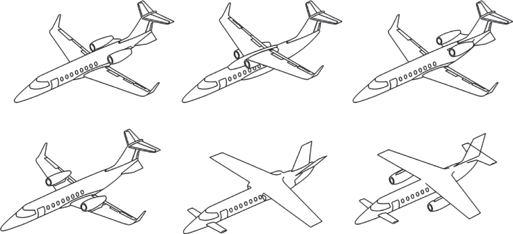
Figure 8.2 Four candidate aircraft configurations.
Initially, the NAP relies on the statistics of existing aircraft within the class as well doing competition analysis of potential competitors. In fact, market analyses should be aware of new aircraft capabilities offered by competitors. If required, the market specifications/requirements should be revised before start‐up to stay ahead of competition. Then, by incorporating proven advanced technologies, the NAP offers the best value candidate configurations.
Past designs offer good insight to move into future designs. At the start, only a few parameters will be required to propose a few candidate aircraft configurations to make the choice. Each company maintains a strong database of all operating aircraft in the class. Chapter 7 gives some statistical databases for trend analyses. To improve resolution, readers are recommended to prepare their own statistics of, say, 5–10 aircraft within the class of their project design. Experienced designers can make good guesses of what are expected, thereby reducing the number of iterations to improve accuracy, saving design man‐hour costs.
Initially, the conceptual study proposes several preliminary candidate aircraft configurations to search for the best choice. Comparative studies are carried out to confirm which choice provides the best economic gains. Figure 8.2 shows six possible configurations (author‐generated for coursework only). Eventually, the best configuration in the figure is selected through a series of design reviews with the customers and management (the first configuration offers the best market potential.).
The first configuration offers the best market . The chosen configuration is sized with matched engine in an iterative process to a satisfying baseline design, which implies that while none of the variants is an ‘optimised’ design, the family of variants in the project offers a ‘satisfying’ design to widen the market to amortise initial investment at a slightly increased design cost frame. Retaining maximum component commonalities within the variant designs helps in reducing the aircraft price.
8.3.2 Methodology for Shaping and Laying out of Civil Aircraft Configuration
This section takes a closer look of the Phase I stage of a new aircraft project as given in Chart 2.2. The initial stages of the Phase I is the concept definition, as described in Chart 8.1, which gives some idea on how a project starts. This chapter deals only with Step 1 of the Chart 8.1. Thereafter, typically, the process cascades down carrying out the concept finalisation in a step‐by‐step manner.

Phase I, conceptual study: methodology for finalising civil aircraft configurations.
The methodology starts with shaping the aircraft components; for example, wing planform, fuselage shape, nacelle/intake shapes and empennage and establish their external geometries. These components serve as ‘building blocks’ to assemble them to configure the new aircraft.
Step 1 is based on ‘guesstimates’ using the statistics of past designs. Designers then incorporate proven LE advanced technologies without compromising safety to stay ahead of competition. Given next are the Step 1 sequences in Chart 8.1, in a step‐by‐step manner,
- From the statistics of payload‐range, obtain a preliminary MTOW that will be improved through iterations.
- From the statistics of MTOW versus wing area, develop a preliminary wing planform with the specified technology level. Next, position the wing with respect to the fuselage in an approximate position from past experience (typically, begin with the MAC1/4 slightly ahead of mid‐fuselage). Size and position the empennage in relation to wing area (readers may study comparable existing designs). This gives the preliminary wing loading, W/Sw, which can be compared with the statistics of comparable operating aircraft. Note that moving wing position will also move the aircraft CG, therefore some iterations are required.
- Select the engine from what is available. The thrust loading will invariably fall within 0.32–0.35 for two‐engine and 0.3–0.33 for four‐engine aircraft. For propeller powered aircraft, divide the thrust by 3.5 to get the shaft horse power (SHP). Later, the engines will be properly sized to match the aircraft.
The other steps from two to six in Chart 8.1 continue in the following chapters. In the process, the preliminary geometry, weight and engine size will be revised to better accuracy leading to the final design. Finalising the aircraft configuration, as a marketable product, follows the formal methodology of aircraft sizing and engine matching (Step 6 of Chart 8.1) and is an iterative process.
8.3.3 Shaping and Laying out of Civil Aircraft Components
The objective is to generate aircraft components, piece by piece in a building‐block fashion, and mate them as shown in the middle diagram of Figure 2.1. The diagram also gives a more detailed breakdown of the aircraft components in subassembly groups for a better understanding of the preliminary layout of the internal structures that facilitates preliminary cost estimates.
A lot of information has been captured within Section 7.5. This section summarises some of the points arising out of these sections. The nine graphs in Figures 7.1–7.9 capture all the real aircraft data taken from [1–9] and other sources. These statistical data (with some dispersion) prove very informative at the conceptual design stage to get an idea of what options a new design can incorporate to stay ahead of competition with a superior product. With these nine graphs one can figure out what to expect from the basic specification of payload‐range. The readers may have to wait until the project is completed (a better appreciation will emerge after completing the sizing exercise shown in Chapter 16) to compare how close it is with the statistical data. There should be no surprise if the classroom result falls within the statistical envelope.
As it progresses with better definition, the aircraft‐component weights are revised for better accuracy that may require revising the aircraft wing position to getting the aircraft CG at approximately a quarter chord of the MAC. Changing wing position changes CG location, known as wing chasing.
Section 6.7 dealt with empennage sizing. At this stage, it may prove cost effective to keep the control surface sizes taken from the existing statistics of comparable designs. The control surfaces can be formally sized to better accuracy in Phase II study using CFD/wind‐tunnel tests (datasheets may prove useful but this practice is gradually receding). Finalisation of control area size is determined in a subjective assessment of various test pilots with a consensus of what is acceptable.
Sections 3.15 and 4.19 summarised that aircraft speed capability influences the aerofoil choice and wing shaping, respectively, implying that compressibility effects of air dictate the shaping of aircraft configuration in the following three categories.
- Aircraft design speed below Mach 0.6.
Influence of the compressibility effects of air can be neglected for aircraft maximum design speed is below Mach 0.6, when CDW ≈ 0. There are not many aircraft operating within Mach 0.6 and 0.7. Chapter 12 discusses that propeller efficiency reduces above Mach 0.6 and jet propulsion is inefficient below Mach 0.6.
- Aircraft design speed above Mach 0.6 and below Mach 0.95.
Above Mach 0.7 speed capability, compressibility plays increasing role in shaping aircraft as speed capability increases. Shaping aircraft, for example, incorporating wing sweep, use of thinner aerofoil sections, fuselage area ruling, and so on to minimise the rise of wave drag, CDW.
- Aircraft design speed above Mach 0.95
At transonic speed region, wave drag increases drastically there no aircraft designed to fly above Mach 0.95 until it goes well past Mach 1.4. For speed above Mach 1.4 and up to 2.4, aircraft shaping requires addressing the issues arising from the effects of the presence of shock waves. The aircraft becomes slenderer with a sharper nose cone and wing leading edge, the aerofoil becomes very thin and so on. Thermal effects limit the aluminium frame not to exceed Mach 2.4. (The Lockheed SR71 Blackbird speed capability achieved Mach 3.4 with a titanium frame, a record remained unbroken for more than half a century.)
Today, industry uses computer aided drawing (CAD)‐generated aircraft configurations as an integral part of the conceptual design process, which must be implemented in classwork. Having CAD 3D parametric modelling allows changes to be easily, quickly and accurately incorporated. Making 2D drawings (i.e. three‐view) from 3D models is simple with few keystrokes. Sections 8.4–8.7 configure the aircraft components of civil transport category aircraft.
8.4 Fuselage Design
Chapter 5 is devoted to fuselage design. The commercial aircraft fuselage is a hollow shell accommodating the payload (passenger/cargo) and its mid‐section typically has a constant cross‐section. For transport aircraft design, it is convenient to start with fuselage shaping as it is determined from its specified passenger number and comfort level; that is, from the specified passenger capacity, the number of seats abreast and number of rows and facilities provided. In other words, fuselage design is not derived from empirical equations. Fuselage design parameters show strong statistical correlations as covered in Chapter 7.
Comfort level is an important parameter in free market competition. Higher comfort level with more space for passengers is preferred and results in a wider fuselage at the expense of higher drag and weight, making it more expensive to operate, thus affecting profit margins essential for industry growth and vice versa. A compromise is required to obtain the best fuselage width. In this book, medium comfort level is taken as given in Table 7.2. The aerodynamic design considerations of these types of bodies are not as stringent as wing/empennage considerations as they are not meant to generate lift to sustain flight and control aircraft performance. The main aerodynamic considerations are to reduce drag and moment of the bodies. In this book, the fore and aft closure designs of fuselage are guided by the statistics of existing designs taking care of other requirements for example, to provide takeoff rotational clearance, requirements of flight crew. Considerations for the Maintenance, Repair and Overhaul (MRO) issues and so on are to be made.
Being subsonic in operation, its front end is blunter in a favourable pressure gradient and the rear end tapers gradually to a closure in adverse pressure gradient to minimise boundary layer separation, unless it is designed for special purpose, for example, having a door for rear loading. A carefully shaped conventional fuselage can generate a very small amount lift, say about 2% of aircraft weight. The top mouldline of the fuselage contour is more curved than the bottom keel mouldline, which permits a very small amount of lift. Wing‐body blended aircraft configurations are not dealt with in this book.
8.4.1 Considerations Needed to Configure the Fuselage
Section 6.7 describes typical fuselage layouts from two‐abreast seating to the current widest seating of 10 abreast. The following are the general considerations for the fuselage layout.
| Geometry | Aerodynamics |
|
|
|
|
| Structure (affecting weight and external geometry) | Systems |
|
|
8.4.1.1 Methodology for Fuselage Design
Fuselage size is determined from required passenger capacity. The current International Civil Aviation Organization (ICAO) limit on fuselage length is 80 m, an artificial one based on current airport infrastructure size and handling limitations. The following are the considerations for the methodology, given in a step‐by‐step approach to configure a fuselage.
- Step 1: Fuselage cross‐section and seating arrangement.
Decide on the abreast seating arrangement corresponding to passenger number as given in Table 5.3. For the specified comfort level, find cabin and fuselage width (Figure 5.8) and height. Adding the fuselage thickness, it will give the fuselage height and width. For aircraft that are four abreast or more, under floorboard space provision needs to be considered. A pressurised fuselage would invariably be circular or near circular to minimise weight. Unpressurised cabins for aircraft operating below 4300 m (14 000 ft) need not be circular in cross‐section. Smaller utility aircraft would show the benefits of having a rectangular cross‐section. A box‐like rectangular cross‐section (Figure 4.7) would not only offer more leg room but would also be considerably cheaper to manufacture. Based on below floorboard space provision requirements and whether the cabin is pressurised or not, the fuselage cross‐section shape is developed.
- Step 2: Fuselage mid‐section
Step 1 has established the abreast seating and fuselage width. The mid‐fuselage is mostly of a constant cross‐section. Determine the number of seat rows by dividing total passenger capacity by number of abreast seating. If it is not divisible then the extreme rows will have fewer seats abreast. The end extremity of the fuselage mid‐section can get tapered as a start for fuselage closure. CFD analyses of the closure aerodynamics have to confirm that the pressure distribution around the closures is satisfactory with special attention to ensure to keep aft closure boundary separation to its minimum. The aft luggage space in front of the pressure bulkhead can exist, especially for small aircraft.
Decide on the passenger facilities – for example, toilets, galleys, closets, cabin crew seating and so on – and their dimensions to be added: the extent depends on number of passengers and duration of flight. Chapter 7 describes toilet and galley details. For small aircraft with shorter flight durations, it is desirable that a toilet be provided. There are small aircraft of low mission range without a toilet to keep cost down, but these could prove uncomfortable.
- Step 3: Fuselage front and aft closure sections and the fuselage length
When the seating arrangement is determined in the mid‐fuselage section, it must be closed at the front and aft ends for a streamlined shape, maintaining a fineness ratio within 7–14 (see Table 5.3). Typical front and aft‐fuselage closure ratios are given in Table 5.1. There is a wide choice as can be observed from the past designs within the class of aircraft. While benefiting from past experience, designers develop their own configuration to improved pilot vision, drag considerations, space for storage, rotation for takeoff and so on. Adding front and aft closure to the fuselage mid‐section gives the fuselage length. Front and aft fuselages have their respective bulkheads to give a sealed cabin for pressurisation.
The fuselage upsweep angle of the aft‐end closure depends on the type of aircraft. If it has a rear‐loading ramp as in a cargo version, then the upsweep angle is higher. The fuselage takeoff rotation clearance angle, θ (see Figure 5.6 and Figure 9.9), depends on the main‐wheel position of the undercarriage relative to the aircraft CG position (see Chapter 7). The typical angle for θ is between 12 and 16° to approach CLmax at aircraft rotation.
- Step 4: Locate the position and sizes of aircraft doors, windows, hatchets
Federal Aviation Administration (FAA) and Civil Aeronautics Agency (CAA) have mandatory requirements on minimum number of passenger doors, their types and corresponding sizes, depending on the maximum passenger capacity the fuselage is intended to accommodate. This is to ensure passenger safety – certification authorities stipulate a time limit (90 s for big jets) within which all passengers must egress if an unlikely event, for example, a fire occurs. The larger the passenger capacity, the higher the minimum number of doors is to be installed. Not all doors are of same size – the emergency doors are smaller. Passenger doors have several categories and are dealt with in Section 5.5.5. All doors are kept armed during airborne operation.
Other Points
- Two‐abreast seating cabin height is typically less than 6 ft and has constrained leg space. Three‐abreast seating, if required, with floorboard recess, will allow standing room and better leg room (Figure 5.10). For a fuselage with four‐abreast seating or more, the cross‐section could use below floorboard space. Full standing headroom is easily achievable for a fuselage with four‐abreast seating or more.
- Two aisles are provided for a fuselage with seven‐abreast seating and more (current maximum is 10 abreast). In future, if wider cabin appears (say with BWB), then more than two aisles would be necessary.
- The minimum number of cabin crew is dependent on the maximum number of passenger capacity the airframe can take. Cabin crew is not required up to 19 passengers but some operators provide one.
- It is necessary to set the zero reference plane (ZRP) and assign a fuselage axis line (see Section 5.3.1). It assists in tracking the aircraft‐component positions along the fuselage axis. For smaller civil aircraft, there is no constant fuselage section, and the aircraft centreline must be conveniently chosen; it is the designer's choice as long as the reference lines are clearly defined and adhered to for the entire life cycle of an aircraft that could encounter design modifications in its service life.
- Fuselage splitting plane. An interesting concept is to make variants of a modular fuselage – that is, with two types of aft ends easily interchangeable. One type is for the conventional passenger version with a pointed aft‐end closure, the other is for the cargo version with an increased upsweep to accommodate a rear‐loading ramp. Figure 8.3 shows the concept of a ‘quick‐change’ convertible fuselage. The aft fuselage can be split to accept either a passenger version or a rear‐loading cargo version, as the mission demands. The changeover splitting joint is located behind the main undercarriage.

Figure 8.3 Convertible fuselage.
8.5 Wing Design
Chapter 4 is devoted to wing design. The first task for wing design is to select an aerofoil suitable for the desired aircraft performance characteristics. This book does not undertake aerofoil design; rather, it uses established 2D aerofoil data from the public domain (the NACA aerofoil data [1] in Appendix C are sufficient for this book). Industry takes an arduous route to extract as much benefit as possible from its in‐house research that is kept commercial in confidence. It is an established technology in which there is a diminishing return on investment. However, the differences between the best designs and those in the public domain are enough to encourage industrial competition.
The next task is to configure a wing planform with a reference area typically for the class of aircraft. It is not determined by the passenger number as in the fuselage. Initially, corresponding to the guessed MTOM, the wing reference area is estimated from statistics. Some iteration is required because component weights are revised at the stages of progresses. Subsequently, the preliminary wing reference area must be sized using the methodology described in Chapter 14.
At the conceptual stage of the project study, typical values of wing twist and other refinements are also taken from the past experience of a designer. The values must be substantiated through CFD analysis and wind‐tunnel testing to a point when the flight‐test may require final local refinements (e.g. flap and aileron rigging). Initially, an isolated wing is analysed to quickly arrive at a suitable geometry and then studied with the fuselage integrated.
A generous wing root fairing is used to reduce interference drag as well as vortex intensity at the aft‐fuselage flow. There is no analytical expression to specify the fairing curvature – a designer should judge the geometry from past experience and CFD analysis, considering the associated weight growth. In principle, a trade‐off study between weight growth and drag reduction is needed to establish the fairing curvature. At this stage, visual approximation from past experience is sufficient. Observe the current designs and make decisions.
8.5.1 Considerations in Configuring the Wing
The following are general important considerations when designing the wing:
| Geometry | Aerodynamics |
|
|
| Structure (affecting weight and external geometry) | Systems |
|
|
Chapter 4 is devoted to wing design, dealing with the roles of wing sweep, wing twist and wing dihedral/anhedral angle. Figure 4.27 summarised the role of aircraft speed capability influencing wing sweep and its aerofoil thickness to chord ratio. A major requirement is to make the wing root stall earlier to retain aileron effectiveness at a high angle of attack (low speed) – especially during landings. A wing twist with washout would favour such behaviour (and is the prevailing practice). Generally, the dihedral is associated with low‐wing design and the anhedral with high‐wing design; however, there are designs that are the reverse; a high wing can accommodate a dihedral.
8.5.2 Methodology for Wing Design
Section 4.16 may be revisited to obtain a summary of design. Given next is a stepwise approach to wing design.
- Step 1: Decide on the aerofoil selection
Chapter 3 is devoted to aerofoil selection. Aerofoil selection is one of the most important aspects of aircraft design. Aircraft performance depends considerably on the type of aerofoil adopted. Aerofoil design is a protracted and complex process that is beyond the scope of this book. Section 3.7 outlines the strategy to search for an aerofoil that would provide a high CLmax as well as a high‐lift‐curve slope (dCL/dα), a high L/D ratio for the prescribed cruise speed, a low pitching moment and gentle stalling characteristics. Aerodynamicists prefer aerofoils to be as thin as possible but structural engineers prefer them as thick as possible. A compromise is reached based on aircraft design Mach number and the chosen wing sweep (Figure 4.27). Aerofoils can vary spanwise.
- Step 2: Establish wing reference (planform) area
Initially, the wing referenced area has to be guessed from past statistics. The first estimate comes from aircraft MTOW in the payload‐range capability (Figure 7.1). Next is to estimate the wing reference (planform) area, SW, from the estimated MTOW (Figure 7.5). This will give the wing loading. Both the SW and MTOW will be accurately sized in Chapter 14.
- Step 3: Establish wing geometric shape and the associated details
Establish: (i) aspect ratio, (ii) wing sweep, (iii) taper ratio, (iv) twist and (v) dihedral (Section 3.16). The choice for wing aspect ratio, wing sweep and taper ratio are interlinked with the aircraft maximum speed to keep the compressibility drag rise within 20 drag counts at the high speed design specification (Section 4.19.1). In general, the wing planform is of a trapezoidal shape but not necessarily restricted to this; it can be modified with a glove and/or yehudi. Given next are the pertinent points associated with these five parameters.
- Aspect ratio
- Determine the aspect ratio, this should be the highest the structural integrity will permit (in consultation with stress‐engineers) for the aerofoil thickness to chord ratio and the wing root chord based on the taper ratio. This minimises induced drag (see Eq. (4.18)). The V‐n diagram (see Chapter 17) determines the strength requirement in pitching manoeuvres creating maximum stress from the bending moment at the wing root. Civil aircraft do not have high roll rates (unless it is a small aerobatic aircraft). Choice of material and aerofoil t/c ratio contributes to structural integrity.
- Wing sweep
- Determine the wing sweep, which is dependent on maximum cruise speed (Figure 4.23).
- Taper ratio
- For civil aircraft, a trapezoidal wing planform would be the dominant choice with taper ratio ≈(0.3 < λ < 04).
- Twist
- At this stage, wing twist is empirically determined to improve stalling effects. Determine the wing twist; a typical value is 1–2°, mostly as washout.
- Dihedral
- Determine the wing dihedral/anhedral angle; initially, this is from the statistical data (Section 4.4.2). Typical values are dihedral ≈3–5° and anhedral ≈0–−3°.
- Aspect ratio
- These five parameters are eventually substantiated through CFD analysis and wind‐tunnel testing hoping that flight test results will not require further tweaking.
- Step 4: Position wing Relative to the fuselage
Positioning of the wing relative to the fuselage requires the location of CG and its range of movement with weight variation (i.e. fuel and payload). The positioning of the wing should be such that the aircraft stability margin is not jeopardised by extremes of the operational CG position. The positioning of the wing relative to the fuselage is an iterative process dictated by the location of the aircraft CG at a desired position, expressed in terms of the percentage of the wing MAC. The aircraft weight distribution and CG location are yet to be established, it is initially estimated based on experience and past statistics in the aircraft class. If nothing is known, then a designer may position the wing MAC around the middle of the fuselage for rear‐mounted engines or slightly ahead of the mid‐fuselage for wing‐mounted engines.
Subsequently, the wing position gets iterated as aircraft and its components weights are known (Chapter 10). This may not be easy because moving the wing will alter the CG position – an inexperienced engineer could encounter wing chasing. For newcomers to aircraft design, this offers an interesting exercise: However, this is not a major concern as very quickly, a ‘feel’ for locating the wing can be developed. The wing positions are tracked along the fuselage from the aircraft ZRP in the attempt to arrive at a desired position. Experienced designers minimise the number of iterations that could occur with wing chasing,
- Step 5: Establish wing high‐lift devices
Section 4.15 is devoted to high‐lift device aerodynamics and their configuration types. Flaps and slats are wing components, the selection of the type depends on the field performance demands to generate high lift. In general, the more demanding the requirements, the more sophisticated the high‐lift devices, which gets progressively more complex and therefore more expensive and heavier. Associated incremental lift gains by each type are shown in Figure 4.37. In general, single‐ or double‐slotted Fowler action flaps suffice for the majority of smaller civil transport aircraft (Bizjets/Regional jets). Fowler action designs increase wing planform area and lift as well as an increase in nose‐down pitching moment.
The first task is to decide the type of high‐lift device required to meet the maximum CLmax to satisfy the specified field performances (takeoff and landing). Once the type of high‐lift device selected, their area and other geometrical parameters are initially earmarked from statistics/semi‐empirical data. Flaps are positioned behind the wing rear spar (about 60–66% of the chord) and typically run straight or piecewise. Flaps take up about two‐thirds of the inner wing span. It is apparent that designers must have a good knowledge of the internal structural layout to configure an aircraft. In this book high‐lift devices are not sized, but positions are earmarked.
- Step 6: Wing‐mounted control surfaces areas and their locations
Section 4.16 is introduces wing a host of wing‐mounted control surfaces (e.g. aileron, flap, slat, spoilers and trim tabs), none of which are sized in this book. Initially, their geometries are extracted from the statistics of current designs or determined using semi‐empirically relations. At this stage, their placement and positing are earmarked in this book. Control surface sizing is accomplished after the wing is sized and is addressed in subsequent design phases.
The aileron span is about a third of the wing span at the extremities. Ailerons and flaps are hinged aft of the rear spar for up and down movements; provision for them should be made during the conceptual design phase. A flaperon serves as both a flap and an aileron.
Not all aircraft have wing spoilers; however, aircraft with speed over Mach 0.7 generally have spoilers. These are installed close to the aircraft CG line to minimise pitch change. Spoilers act as air brakes and as lift dumpers during landing. The differential use of spoilers is for lateral control and they are referred to as spoilerons.
8.5.3 Structural Consideration for a Wing Attachment Along a Fuselage Layout
Structural considerations for attaching the wing to the fuselage are discussed in detail in Section 4.16. In summary, wing design has to consider the wing fuselage attachment option, which can affect the local fuselage external shape.
8.6 Empennage Design
Chapter 6 covered empennage design. This book deals only with conventional empennage design, for example, a V‐tail and a H‐tail orthogonal (near) to each other. Empennage design is quite complex as it depends on fuselage and wing sizes, those have to be configured first. The fuselage length, wing reference area (SW), and tail arms LHT and LVT are the main parameters governing the empennage sizes, SHT and SVT. The two important parameters interlinking the relationship are defined in Eqs. (6.1) and (6.2) as follows.
Taking the CHT and CVT values from statistics, the respective empennage areas SHT and SVT can be computed from these equations. The empennage size needs to be checked out for the extreme limits of forward and aft positions of the aircraft CG when the aircraft and its component weights are known. Graphs in Figure 7.8 give the statistics and there is a wide spread in the data. The current design tendency indicates a little higher tail volume coefficient compared to the historical design trend. (Examples 6.1 and 6.2 give the DATCOM method, but at this stage it is justified to use statistics to get empennage areas as shown in Example 6.3.)
The H‐tail is placed as a T‐tail on a swept‐back V‐tail that would provide an increased tail arm, LHT and LVT, which would save weight by not having a longer fuselage. Smaller aircraft would benefit from a T‐tail; however, to support the T‐tail load, the V‐tail must be made stronger with a small increase in its weight. Care must be taken to ensure that the T‐tail does not enter the wing wake at a high angle of attack. This can be achieved by positioning it high above the wing wake at near stall or having a larger H‐tail and/or an all‐moving H‐tail acting as an elevator. Also, the positioning of the H‐tail has to consider its relative placement with respect to V‐tail to minimise shielding. H‐tail and V‐tail designs are discussed separately in the following subsections.
8.6.1 Horizontal Tail
Typically, for civil aircraft, the H‐tail planform area is from one‐fifth to one‐quarter of the wing planform size, aspect ratio, AR ≈ 3.0–3.5. As in wing design, the H‐tail can have a sweep and a dihedral (a twist is not required). Sweeping of the H‐tail would effectively increase the tail arm LHT, which is an important consideration when sizing the H‐tail. For a T‐tail configuration, the tail arm further increases. The H‐tail camber is influenced by the aircraft's CG position. In general, negative camber is used to counter a nose‐down moment of the wing. At a high angle of attack, the H‐tail should not remain within the wing wake; otherwise, it must be enlarged to be effective.
8.6.2 Vertical Tail
The V‐tail can have a sweep, but the dihedral and anhedral angles and the twist are meaningless because the V‐tail needs to be symmetric about the fuselage centreline. Typically, for civil aircraft, the V‐tail planform area is about 12–20% of the wing reference area, aspect ratio, AR ≈ 1.0–1.5. From the statistics given in Figure 7.8, it can be seen that there is a cluster of V‐tail designs with a tail volume coefficient of 0.07. For the T‐tail configuration, the tail volume coefficient could be reduced to 0.06 because the T‐tail acts as an endplate at the tip of the V‐tail. Sweeping of the V‐tail would effectively increase the tail arm LVT, an important dimension in sizing the V‐tail.
It is important that the V‐tail remains effective for the full flight envelope. The V‐tail, especially the rudder, must not be shielded by the H‐tail to retain effectiveness, especially during spin recovery. Shielding of the V‐tail, especially the control areas, may prove to be dangerous. A designer must ensure that at least 50% of the rudder stays unshielded at a high angle of attack. With a T‐tail, there is no shielding of rudder.
The V‐tail design is critical to takeoff – especially in tackling yawed ground speed resulting from a crosswind and/or asymmetric power of a multiengine aircraft. A large V‐tail can cause snaking of the flight path at low speed, which can be resolved easily by introducing a ‘yaw‐damper’ (a matter of aircraft control analysis). At cruise, a relatively large V‐tail is not a major concern. For propeller‐driven aircraft, the V‐tail could be kept slightly skewed (less than 1°) to offset a swirled‐slipstream effect and gyroscopic torque of rotating engines and propellers.
8.6.2.1 Typical Values of Tail Volume Coefficients
Typically, CHT and CVT depend on the class of aircraft under study. The following values of CHT and CVT may be used for the category of aircraft under consideration.
| Category | Typical speed in knots (kt) or Mach |
| Home‐builds – Light Sports Aircraft (LSA) | Maximum never exceed speed ≤120 kt |
| Club trainers – Normal Category (FAR 23) | Around 150 kt |
| Utility – Normal Category (FAR 23) | Around 200–250 kt |
| Aerobatic – Normal Category (FAR 23) | Around 200–300 kt |
| Bizjets – FAR 25 | Around Mach 0.65–0.75 |
| Commercial jets | High subsonic around Mach 0.75–0.95 |
Table 8.2 may be compacted in Table 8.3 based on aircraft MTOM, that is, its size. Larger civil aircraft have higher tail volume coefficients. A large V‐tail is required to retain control authority during high level cross wind field performances.
Table 8.2 Civil aircraft tail volume coefficients.
| Aircraft category | ≈CHT | ≈CVT | Remarks |
| Home‐builds/club trainers | 0.6 ± 0.1 | 0.06 ± 0.01 | To save cost, home‐builds can get with flat plates as empennage. |
| Aerobatic category | 0.6 ± 0.1 | 0.06 ± 0.01 | Generally with tapered wing planform. Aerobatic with higher control authority. |
| Utility category | 0.7 ± 0.1 | 0.07 ± 0.01 | Generally with tapered wing planform (there are also rectangular planform). |
| Bizjet category | 0.7 ± 0.1 | 0.07 ± 0.01 | Invariably with tapered wing planform. |
| Commercial jets | 0.9 ± 0.2 | 0.09 ± 0.01 | Invariably with tapered wing planform. |
Empennage planform geometry follows the pattern of the wing geometry. Empennage aerofoil thickness to chord ratio, t/c, is in the order of wing t/c, but type can differ.
Table 8.3 Civil aircraft tail volume coefficients.
| H‐tail coefficient | V‐tail coefficient | |
| (CHT) | (CVT) | |
| Small aircraft (≈ < 25 000 lb) | 0.6–0.8 | 0.05–0.08 |
| Medium aircraft (≈25 000–250 000 lb) | 0.8–1.0 | 0.08–0.1 |
| Large aircraft (≈ > 250 000 lb) | 1.0–1.2 | 0.1–0.12 |
Aircraft with FBW system architecture ensures that aircraft operates safely with the operating envelope, hence the empennage can be optimised to a smaller size. If a FBW control system is incorporated, the empennage sizes can be reduced because the aircraft would be able to fly safely under relaxed stabilities. However, this book is not concerned with control laws as design input in an introductory course. The FBW concept is introduced in Chapter 18 but not analysed. It will not be long until tailless aircraft, such as the B2 bomber, appear in civil aircraft designs, especially for BWB aircraft.
8.6.3 Considerations in Configuring the Empennage
The following are general considerations important when configuring the empennage:
| Geometry | Aerodynamics |
|
|
| Structure (affecting weight and external geometry) | Systems |
|
|
8.6.4 Methodology for Empennage Design – Positioning and Layout
The empennage design has considerable similarity to the wing design. The following is a stepwise approach to empennage design: It requires some iteration as many parameters are still not known requiring estimated planform geometries taken from existing designs within the class of aircraft. Subsequently, a realistic planform will emerge that will eventually be fine‐tuned through flight testing. Given next is a stepwise approach to empennage design.
- Step 1: Decide the aerofoil section
In general, the V‐tail aerofoil section is symmetrical but the H‐tail has an inverted section with some (negative) camber. The t/c ratio of the empennage is close to the wing‐aerofoil considerations. A compromise is selected based on the aircraft design Mach number and the wing sweep chosen.
- Step 2: Position wing with respect to fuselage
From statistics, obtain the tentative empennage areas from Figure 7.8, which shows spread and likely to read higher areas than what is required. This preliminary area is needed to position the empennage with respect to fuselage to compute tail arms as stated in Step 3. Find the empennage areas geometry using typical aspect ratio and taper ratio and span. For aircraft with a T‐tail arrangement, position the V‐tail as far aft in a position suiting the structural arrangement of its main spar with a ‘banjo frame’ or any other arrangement going through the fuselage (Figure 19.31). Place the horizontal T‐tail at the top of the V‐tail. Fuselage mounted low H‐tail positioning is done in conjunction with positioning the V‐tail to avoid rudder shielding and wing wake consideration (Figures 6.14 and 6.15). The empennage areas will be revised in Step 4, based on empennage areas computed using a tail volume coefficient obtained from stability Eqs. (6.1) and (6.2).
- Step 3: Compute tail arms and choose tail volume coefficients, CHT and CVT
Measure the tail arms LHT from the wing MAC1/4‐chord aircraft to the H‐tail MAC1/4‐chord and LVT from the wing MAC1/4‐chord aircraft to the V‐tail MAC1/4‐chord. Empennage geometries are still not known. Take tail volume coefficients, CHT and CVT, respectively using Table 8.1. CHT and CVT also have wide spread in the statistics as shown in Figure 7.8. The spread of the tail volume coefficients have been narrowed down in Table 8.2 to usable values for this book. Industries also use the tail volume coefficients, CHT and CVT, from their own data bank statistics, substantiated by flight testing: these are more appropriate than the values given in Table 8.2.
- Step 4: Estimate empennage reference (planform) area
From the tail volume coefficients, CHT and CVT, obtain in Step 3 compute the H‐ and V‐tail planform areas using Eq. (6.1) and (6.2). Discard the earlier values empennage areas taken from statistics taken from Figure 7.8 as done in Step 2.
- Step 5: Configure the geometric details of the empennage areas
Configure H‐ and V‐tail planform geometries, that is, the aspect ratio, sweep, taper ratio and dihedral angle. These will give the empennage root chord and tip chord. Next, settle for the H‐tail incidence αHT, if riggable, the value can be fine‐tuned after flight tests.
The empennage planform is generally but not restricted to a trapezoidal shape. A strake‐like surface could be extended to serve the same aerodynamic gains as for the wing. The choices for the empennage aspect ratio, wing sweep and taper ratio are interlinked and follow the same approach as for the wing design. The empennage aspect ratio is considerably lower than that of the wing.
- Step 6: Establish control surfaces
Initially, the control areas and dimensions of the elevator and the fin are earmarked from statistics and semi‐empirical data. At this stage of study, the control surfaces can be postponed until more details are available to accurately size the control areas. In this book, the control surfaces are not sized. Subsequently, in the next design phase, when the finalised aircraft geometry is available, the empennage dimensions are established by formal aircraft control analysis.
All these parameters are decided from stability considerations and eventually fine‐tuned through CFD analysis and wind‐tunnel testing, with the hope that flight test results will not require further tweaking. Subsequently, the static stability to be computed about aircraft the forward‐most and aftward most aircraft CGs.
8.6.4.1 Check Aircraft Variant Empennage
To retain component commonality, the same empennage is used in all variants. It is therefore necessary to check whether the empennage falls within the statistical range. For aircraft with a family of variant designs, the empennage design should be done for the variant most suited to retain component commonality, that is, to use the same empennage for all variants. In this case, the empennage requires a small change in planform area, it is easier to reduce the size by chopping off the tips than extending them. Manufacturing jigs should have this provision.
8.7 Nacelle and Pylon Design
Section 5.12 is devoted to nacelle design. Civil aircraft designs are invariably externally pod‐mounted engines on either the wing or the aft fuselage. Most turboprop engines are mounted on the wing, except very few like the P.180 Avanti. The demonstration of high engine reliability enables extended twin operations (ETOPS) clearance by the FAA for a two‐engine configuration. Three‐engine designs (e.g. B727, DC10 and Lockheed Tristar) are no longer pursued except for a few designs.
Nacelles should have their thrust lines positioned close to the aircraft CG to minimise associated pitching moments. In general, the nacelle aft end is slightly inclined (i.e. 1–1.5°) downward, which also assists in takeoff. Wing‐mounted engines are preferred as the engine weight gives relief to the wing bending moment in flight. An underwing‐mounted nacelle should remain clear of the ground in the event of a nose wheel collapse. In case of under‐wing mounted nacelle pods, a minimum of 30° of separation is necessary to avoid wheel‐spray ingestion.
Because of the lack of ground clearance for smaller aircraft, engines are mounted on the fuselage aft end, forcing the H‐tail to be placed higher. Aft‐mounted engines are less desirable than wing‐mounted engines. It is for this reason that the designers of smaller aircraft are currently considering mounting the engine over the wing, as in the Honda small‐jet‐aircraft design.
The keel cut is typically thicker than the crown cut to house accessories. Numerous engine accessories are part of the engine power plant. They are located externally around the casing of the engine (i.e. turbofan or turboprop). In general, these accessories are located below the engine; some are distributed at the sides (if the engine is under‐wing mounted with less ground clearance). Therefore, the nacelle pods are not purely axisymmetric and show faired bulges where the accessories are located. In this book, the nacelle is symmetrical to the vertical plane but it is not a requirement. This book deals only with the long‐duct nacelles for the reasons given Section 12.12.1.
Pylons are the supporting structures (i.e. a cross‐section streamlined to the aerofoil shape) of the nacelle attaching to the aircraft and carrying all the linkages for engine operation. Aft‐fuselage‐mounted pylons are generally horizontal but can be inclined if the nacelle inlet must be raised. For wing‐mounted nacelles, the pylon is invariably vertical (for aerodynamic reason to reduce interference drag take slightly curve shape like banana). The depth of the pylon is about half of the engine‐face diameter; the pylon length depends on the engine position. For an aft‐fuselage‐mounted installation, the pylon is nearly as long as the nacelle. For a wing‐mounted installation, the nacelle is positioned ahead of the wing LE to minimise wing interference.
The nacelle position depends on the aircraft size, wing position and stability considerations (see Section 4.10). Subsequently, CFD analysis and wind‐tunnel testing will fine‐tune the nacelle size, shape and position.
8.7.1 Considerations in Configuring the Nacelle
The following are general important considerations for configuring the nacelle (see also Section 8.7):
| Geometry | Aerodynamics |
|
|
| Structure (affecting weight and external geometry) | Systems |
|
|
8.7.2 Methodology for Civil Aircraft Nacelle Pod and Pylon Design
This section provides an example for configuring the nacelle based on an engine supplied by an engine manufacturer. At this stage, the size of an engine is guessed using the statistical data given in Figure 7.9 as uninstalled TSLS per engine based on the number engine installed versus the MTOM of the aircraft. Formal engine sizing and matching is done in Chapter 14. The authors recommend that the readers produce graphs at a higher resolution for the aircraft class under consideration.
It is best to obtain the engine size from the manufacturer as a bought‐out item. Continuous dialogue with engine manufacturers continues with ‘rubberised’ engines (engines scalable and finely tuned to match the aircraft performance requirements for all variants). Unlike aircraft, in general, the external dimensions of variant engines in a family do not change – the thrust variation is accomplished through internal changes of the engine. The same nacelle geometry can be used in all variants. For major variations, the engine size changes slightly, with minimal changes affecting the nacelle mouldlines.
Given next is a stepwise approach to nacelle design.
- Step 1: Find engine size
Guess TSLS per engine corresponding to the MTOM from statistics (Figure 7.9). Select the engine offered by engine manufacturers. This also allows the possibility of variant engines to match the variant aircraft to be designed. Obtain the engine geometry, for example, engine fan face diameter, bare engine length and maximum diameter.
- Step 2: Decide nacelle type
Deicide on the nacelle type: whether it is of a short or long‐duct type, considering the reasons as given Section 12.12.1. Long‐duct nacelles appear to produce higher thrust to offset the weight increase of the nacelle, while at the same time addressing environmental issues including substantial noise reduction. Also, long‐duct designs could prove more suitable to certain types of thrust‐reverser design. This book will only consider long‐duct design but it does not prevent the choice of short‐duct nacelles.
- Step 3: Configure the nacelle pod
For the type of nacelle pod, its geometry is based on the chosen engine fan face diameter, bare engine length and maximum diameter. Given next is a preliminary guide line to developing long‐duct nacelle geometry (short‐duct nacelles follow the same line but the extent of fan cowl depends on the decisions obtained through discussion with aircraft and engine manufacturers for the best option.
(for high bypass ratio (BPR) engines, lower values – can go down as low as 0.6)
Note: (engine fan face diameter) > (last stage turbine diameter).
where 1.5 < k < 2.8, turbofans with a higher BPR have a lower value of k.
- For long‐duct nacelles, the fineness ratio (i.e. length/maximum diameter) is between 2 and 3.
- The keel cut is typically thicker than the crown cut to house accessories. In this book, the nacelle is symmetrical to the vertical plane but it is not a requirement.
- Subsonic nacelle throat area and the highlight (forward‐most point of the intake) areas are sized based on rated air mass flow rate inhaled by the engine. At this stage take inlet highlight area ≈ 0.9 to 0.95 of the engine fan face area, with a diameter, Dfan. Taking the factor 0.95, the intake highlight area,
- Step 4: Positioning the nacelle with respect to aircraft
Decide where to place the nacelle. For small aircraft that do not have enough ground clearance, they are positioned at the aft end (raised, medium or low position with respect to the fuselage – see Figure 8.9, later) in such a way that the exhaust plane does not interfere with empennage and the thrust line favours aircraft stability in both the pitch and yaw plane.
- Step 5: Configure pylons to attach the nacelle to the aircraft
The depth of the pylon is about half of the engine‐face diameter; the pylon length depends on the engine position. For an aft‐fuselage‐mounted installation, the pylon is nearly as long as the nacelle. For a wing‐mounted installation, the nacelle is positioned ahead of the wing LE to minimise wing interference. In general, the t/c ratio of the pylon is between 8 and 10%.
8.8 Undercarriage
Chapter 10 is devoted to undercarriage design considerations. Undercarriage positioning is CG dependent. At this design stage, the CG position is not established because aircraft‐component weights are not known. From experience, the undercarriage may be placed after establishing the CG position and the rotational tail clearances. Ensure that the aircraft does not tip in any direction for all possible weight distributions. (Tipping occurs in some homebuilt designs – especially the canards – when the pilot steps out of the aircraft.) This book addresses only the tricycle type – that is, a forward nose wheel followed by two main wheels behind the aft‐most CG.
8.9 Worked‐Out Example: Configuring a Bizjet Class Aircraft
The purpose of the worked‐out example is only to substantiate the methodology outlined – intensive coursework begins now. The readers should be aware that the worked‐out examples demonstrate only the proposed methodology. The readers are free to configure aircraft with their own choices and can decide their own dimensions of the class of aircraft on which they are working. Readers need not be confined to this class work example and may explore freely; simplicity can be an asset. Readers are required to work out dimensions using the information provided in the following subsections.
The worked example undertaken here is to configure a Learjet45 class Bizjet that offers variants in a family of designs. It is suggested that readers compare this with competition aircraft – this design has more room than is typical of the class. The specifications/requirements and the technology level adopted are given next.
h3
Aircraft Specifications/Requirements
All variants have the following:
- Low‐wing configuration and stabiliser as a T‐tail.
- The high sweep of the V‐tail to increase tail arm of the T‐tail.
- Passenger facilities include a toilet (39.36 in. deep), a galley (30 in. deep), luggage space (18 in. deep) and a wardrobe (12 in. deep).
- Although cabin crew is not required up to 19 passengers, a folded seat for one cabin crew is offered.
Baseline Version (8–10 passengers) – 10 passengers at standard (medium) comfort level.
- Payload: 1100 kg.
- Medium (standard) comfort level: 10 × 100 (baggage included) + 100 = 1100 kg.
- (High comfort level: 8 × 100 + 300 = 1100 kg)
- Range: 2000 miles + reserve
- Cruise altitude = 40 000 ft.,
- Long‐range cruise (LRC) = 0.7 Mach (at high altitude)
- High speed cruise (HSC) = 0.75 Mach
- g‐level: 3.8 to −2
Long Variant (12–14 Passengers)
- Payload: 1500 kg
- Standard comfort level: 14 × 100 (baggage included) + 100 = 1500 kg
- (High comfort level: 12 × 100 + 300 = 1500 kg)
- Range: 2000 nm + reserve
Short Variant (4–6 passengers)
- Payload: 600 kg
- Standard comfort level: 6 × 100 (baggage included) = 600 kg.
- (High comfort level: 4 × 100 + 200 = 600 kg)
- Range: 2000 nm + reserve
Technology Level Adopted
- Wing aerofoil: NACA 65‐410.
- H‐Tail aerofoil: NACA 64‐210 (negative camber).
- V‐Tail aerofoil: NACA 64‐010 (symmetric).
High‐lift device:
- Single‐slotted Fowler flap at wing trailing edge (≈0% of wing), no slats.
- From the test data, the following maximum lift coefficients are given:
| Flap deflection (°) | 0 | 8 | 20 | 40 |
| CLmax | 1.5 | 1.7 | 1.9 | 2.1 |
Power plant
- Two rear fuselage mounted engines.
- Engine: Garrett TFE731 class turbofan (thrust range in the scalable engine family: 3000–3800 lb per engine) with a bypass ratio of 4. Fan face diameter = 0.716 m (28.2 in.), Engine maximum diameter = 1 m (39.28 ft), and bare engine length of 1.547 m (60.9 in.), and a dry weight of 379 kg (836 lb), static air mass flow = 14.6 lb s−1. No thrust reverser. Long‐duct aft‐mounted podded nacelle is specified.
- Electronic Flight Information System (EFIS) type pilot display.
Material (simplified statement):
- Primary structure is all metal. Some secondary structure with composite. Weight saving is taken as 5%.
Statistics of Existing Design with the Class of Aircraft
Readers are suggested to find as many aircraft in the class with a similar payload range and adapt to an approximately similar technology level. Change in technology may not fit to the pattern as shown in the graph (Figure 8.4).
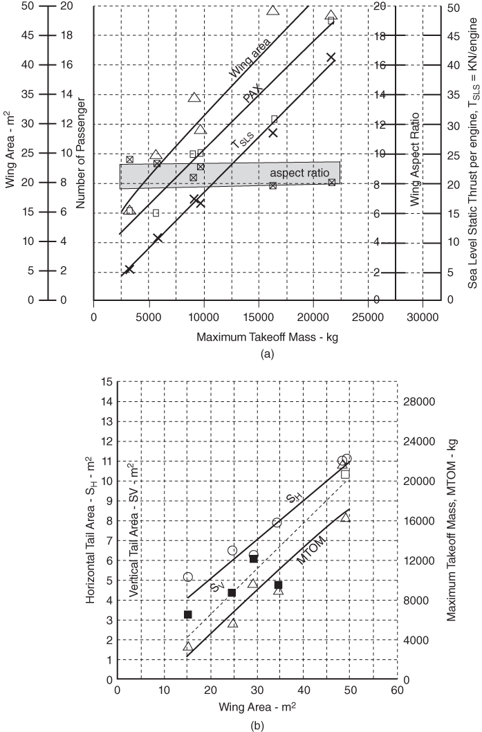
Figure 8.4 Statistics of the Bizjet class of aircraft. (a) PAX versus MTOM and wing . (b) Empennage (SH and SV) – low tail. (Century, Cessna CJ2, Cessna Excel, Cessna 650, Cessna 750 and Challenger.)
To note that the empennage area size depends on tail arm length, this is not compared in the graphs. A coursework example would have a slightly smaller tail area than is shown in Figure 8.4b for a relatively larger tail arm of a T‐tail, with the high sweep of the V‐tail adding to the tail arm. This is an example of a designer's choice for weight reduction). It is the tail volume coefficients that decide the tail areas.
8.9.2 Bizjet Aircraft Fuselage: Typical Shaping and Layout
The following is the stepwise approach as suggested in Section 8.4.1.1; the following geometries for the baseline variant are obtained.
- Step 1: Fuselage cross‐section and seating arrangement
The specified comfort level has the seat pitch = 30 in. at standard (medium) comfort level), seat width = 19 in., aisle width = 19 in. and adding the elbow room of 1.5 in. at the fuselage wall side of a seat and gap of 3 in. between fuselage wall and seat. Adding together gives the cabin with as computed here.
- Cabin width = 19 (seat) + 17 (aisle) + 19 (seat) + 2 × 1.5 (elbow room) + 2 × 3 (gap) = 64 in.
- Next, adding the fuselage shell thickness of 2.5 in. (6.35 cm) at side to get the fuselage width as computed here.
- Fuselage width = 64 + 2 × 2.5 = 69 in. (175 cm).
- Fuselage Height (Depth) = 178 cm (70 in.)
- For a pressurised cabin, the fuselage cross‐section is to be as close as possible to a circular shape. As discussed previously, two‐abreast seating in the cross‐section results in a widening of the bottom half for legroom, shown here in the inclined position for a man in the 95th‐percentile size. The fuselage mid‐section is computed next.
- Step 2: Fuselage mid‐section
Adding the passenger facilities with dimensions given previously, the constant cross‐section mid‐fuselage length is computed as follows.
- Baseline Bizjet – Number of seat rows = 10/2 = 5.

- The long variant Bizjet with 14 passengers at mid‐comfort level has two 30 in. fuselage plugs at each side of the wing to accommodate four additional passengers in two rows.

- The short variant Bizjet with six passengers at mid‐comfort level has two 30 in. fuselage plugs removed from the baseline variant from each side of the wing.


Figure 8.5 Example of configuring the fuselage for the medium comfort level.
All the three variants in the Bizjet family of aircraft cabin and seat layout are shown in Figure 8.5.
- Step 3: Fuselage front and aft sections and the fuselage length
- Front fuselage Take the flight‐deck (cockpit) length = 69 in. (175 cm) as shown in Figure 8.6, and nose cone length = 69 in. (≈175 m) ensuring adequate polar pilot vision. This totals the front fuselage length = 138 in. (3.5 m) with the front closures ratio, Fcf = 138/69 = 2 within the range that Table 5.2 gives (smaller aircraft have larger values).
- Aft fuselage
Take aft closures length, La = 210 in. (≈533 cm). This gives the aft closures ratio, Fcf = 210/69 = 3.0, within the range that Table 5.2 gives. Take aft‐end closure angle = 8° and a takeoff rotation clearance angle of 16° when undercarriage installed (to be checked out later).
The overall fuselage length is reached after adding front and aft closures. The windscreen shape and size must comply with Federal Aviation Regulation (FAR). This is an opportune time to streamline the fuselage, incorporating aesthetics without incurring additional cost and performance degradation. After streamlining, the various ratios are checked out to be within the acceptable range. Use the same closure lengths for all the variants the following are computed. Choosing a suitable ratio, the following dimensions are estimated:
- Fuselage length
The baseline variant Bizjet fuselage length, L = Lf + Lm + La = 138 + 250 + 210 = 598 in. (≈50 ft, 15.2 m).
Fineness ratio = 598/69 = 8.7.
The long variant Bizjet fuselage length, L = Lf + Lm + La = 138 + 310 + 210 = 658 in. (≈55 ft, 16.73 m).
Fineness ratio = 658/69 = 9.54.
The short variant Bizjet fuselage length, L = Lf + Lm + La = 138 + 190 + 210 = 538 in. (≈45 ft, 13.8 m).
Fineness ratio = 538/69 = 7.8.
- Step 4: Locate the position and sizes of aircraft doors, windows, hatchets
Passenger doors have several categories and are dealt with in Section 5.7. Based on the requirements, the positions of the doors, window and hatchets are earmarked.
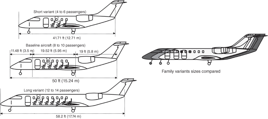
Figure 8.6 Fuselage lengths of the three variants.
The Bizjet must have the following door types:
| Version | Number of passengers | Emergency door type |
| Baseline | 10 | One Type III and one Type IV |
| Long | 14 | One Type III and one Type IV |
| Short | 6 | One Type IV |
- It is better to keep all doors to Type III standards for component commonality, which would reduce production cost.
- Discussion/Rationale Equations/semi‐empirical relations are not used in configuring fuselages. This is developed based on the specification requirements laid down for designers to consider. The fuselage cabin diameter and length is determined from the passenger number and the comfort level specified that have good statistical correlations. For subsonic aircraft, the fore‐end closure is blunter (in favourable pressure gradient) than the aft‐end closure with established closure angles in adverse pressure gradient.
These examples of civil aircraft family derivatives are shown in Figure 8.6 (the completed concept definition); the baseline aircraft is in the middle of the figure. The three variants of the family are shown with the wing positioned nearly at the middle of the fuselage. The rotation clearance is to be checked out after the undercarriage is positioned. This is not a problem because the main undercarriage length can be tailored in conjunction with the longest fuselage; this is an iterative process.
- Discussion/Rationale Equations/semi‐empirical relations are not used in configuring fuselages. This is developed based on the specification requirements laid down for designers to consider. The fuselage cabin diameter and length is determined from the passenger number and the comfort level specified that have good statistical correlations. For subsonic aircraft, the fore‐end closure is blunter (in favourable pressure gradient) than the aft‐end closure with established closure angles in adverse pressure gradient.
8.9.3 Bizjet Aircraft Wing
At the conceptual stage of the project study, typical values of wing twist and other refinements are taken from the past experience of a designer. The following are computed in a stepwise manner as outlined in Section 8.5.2.
- Step 1: Decide the aerofoil section
For a relatively low speed cruise Mach number of 0.7 at the LRC and 0.75 at the HSC, the NACA 65‐410. Design CL ≈ 0.4 at 0.75 Mach (Appendix C gives the NACA 65‐410 aerofoil test data).
- Step 2: Establish wing reference (planform) area
From Figure 8.4a, corresponding to 10 passengers, the guesstimated MTOW ≈ 9500 kg (20 900 lb) and 30 m2 (323 ft2). This gives a wing loading of 317.67 kg m−2 (3108.5 Nm−2 ≈ 65 lb ft−2). The selection is close to final design to avoid iteration in this book; experienced engineers can make selection to minimise iteration.
- Step 3: Establish wing geometric details
In this class of subsonic Bizjet aircraft, the wing planform shape is invariably trapezoidal. As suggested in Section 4.16 that a taper ratio, λ = CT/CR = 0.4 is closed to having highest value of the Oswald's efficiency factor, e.
- Aspect ratio and span
In consultation with structures group, the wing aspect ratio, AR = 7.5.
Wing span is worked out as, b = √ (AR × SW) = √ 225 = 15 m (49.2 ft).
- Sweep
Aircraft specification given at the beginning of this section that HSC speed = 0.74 Mach at MDD. At the LRC of 0.7 Mach it is at the onset of wave drag (CDW = 0) at Mcrit. Example 4.5 in Section 4.8.1 gives for this case wing sweep, Λ1/4_sweep ≈ 14°
- Root chord and tip chord
Other details of wing geometry are as follows.
Wing root and tip chord (CR and CT) can now be worked out from the taper ratio of λ = CT/CR = 0.4.
- SW = 30 = 15 × (CT + CR)/2 solving the equations
- CR = 2.86 m (9.38 ft) and CT = 1.143 m (3.75 ft)
- Using Eq. (3.21), the wing
- MAC = 2/3 × [2.87 + 1.148 − (2.87 × 1.148)/(2.87 + 1.148)] = 2.132 m (7 ft).
- Twist
The wing twist is taken −2°, washout (see Section 3.14).
- Dihedral
The wing dihedral is taken as 3°, typical in this class of aircraft from the statistical data (Section 3.14).
- Aspect ratio and span
- Step 4: Establish wing high‐lift devices
The adopted technology chooses a single‐slotted Fowler flap without a LE slat that would be sufficient, saving considerably on costs. Its lift characteristics are given at the beginning of this section.
- Step 5: Position wing with respect to fuselage
The wing position gets iterated as the aircraft and its components are known (Chapter 10). Positioning of the wing relative to the fuselage is an important part of configuring an aircraft. This may not be easy because moving the wing will alter the CG position – an inexperienced engineer could encounter wing chasing.
The baseline fuselage length is 15.2 m (50 ft). At this stage of design, place mid‐wing MAC (2.132 m) at 7.6 m from the ZRP placed at the tip of the nose cone. There MAC1/4 is at 7.07 m from the aircraft nose (Figure 8.8). (The CG position is still not known. The CG shown in Figure 8.8 is only a marker where to expect. The aircraft CG will be established in Chapter 10. The wing location is subsequently fine‐tuned when the CG and undercarriage positions are known.)
- Step 6: Control surfaces areas and location
Control areas are provisional and are sized in Phase II. Initially, a company's statistical data from previous experience serve as a good guideline. Aileron, flaps and spoilers are placed behind the wing rear spar, which typically runs straight (or piecewise straight) at about 60–66% of the chord. With a simple trapezoidal wing planform, the rear spar runs straight, which keeps manufacturing costs low and the operation simpler; therefore, it has a lower maintenance cost. With a third of the wing span exposed, the aileron area per side is about 1 m2 (10.764 ft2). Similarly, the flap area is 2.2 m2 (23.68 ft2) per side. Subsequent performance analysis would ascertain whether these assumptions satisfy field‐performance specifications. If not, further iterations with improved flap design are carried out.
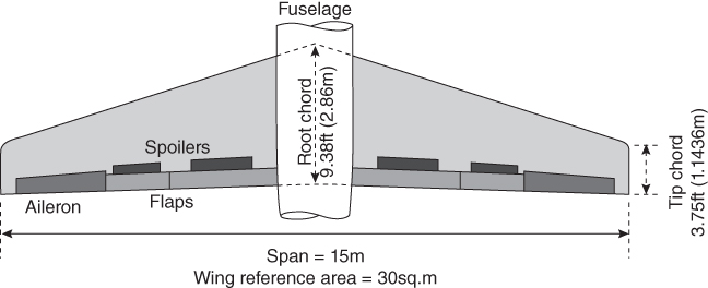
Figure 8.7 Example of wing design.
Figure 8.7 gives the wing geometry. To maintain component commonality, the wing should be the same for all three variants; obviously, it would be slightly larger for the smaller variant and slightly smaller for the larger variant.
- For a small aircraft with limited ground clearance, the engines would be mounted on the rear fuselage. A smaller aircraft wing could be manufactured in one piece and placed under the fuselage floorboards, minimising a ‘pregnant‐looking’ fairing. (Unlike a generous fairing as shown in Figure 4.4 to smooth the hump, this worked‐out example has more streamlined fairing.)
- Discussion/(Rationale given in Chapters 3 and 4) The wing along with the empennage aerodynamics is the most crucial aspect of aircraft design and requires attention. Aircraft performance and the operational economics depend on it. The wing is a lifting surface whose capability depends on the choice of aerofoil to satisfy the specified requirements.
The specified maximum operating speed for Bizjet is 0.75 Mach, a value relatively low compared to high subsonic commercial aircraft cruise speed. Based on the desirable aerofoil characterises required for the subsonic Bizjet, the NACA 65‐410 is chosen that has mid‐cruise design CL = 0.5 at LRC of Mach 0.7 developing wave drag, CDW = 0. The relatively thinner aerofoil thickness to chord ratio, t/c = 10% at wing sweep, Λ1/4_sweep ≈ 14° offers lower wing profile drag in addition to aim for lower induced drag mentioned before.
The wing span and aspect ratio are interrelated for the reference geometry chosen. To keep wing induced drag low, wing sweep is kept low at Λ1/4_sweep ≈ 14° allowing an aspect ratio of 7.5 for wing area of 30 m2 resulting in wing span of 15 m which suits well for the class.
At the conceptual stage of the project study, typical values of wing twist and other refinements are taken from the past experience of a designer. The values must be substantiated and, if required, modified through CFD analysis and wind‐tunnel testing to a point when the flight test may require final local refinements (e.g. flap and aileron rigging). Initially, an isolated wing is analysed to quickly arrive at a suitable geometry and then studied with the fuselage integrated. Subsequently, the wing is sized formally (see Chapter 14).
- Discussion/(Rationale given in Chapters 3 and 4) The wing along with the empennage aerodynamics is the most crucial aspect of aircraft design and requires attention. Aircraft performance and the operational economics depend on it. The wing is a lifting surface whose capability depends on the choice of aerofoil to satisfy the specified requirements.
8.9.4 Bizjet Empennage Design – Positioning and Layout
The low‐wing Bizjet aircraft specifications used so far to configure the fuselage and wing are sufficient for empennage design. Figure 8.4b provides empennage statistics (low tail) of the current Bizjet aircraft class. The positions of the H‐ and V‐tail relative to the fuselage and the wing are decided by considering the aerodynamic, stability, control and structural considerations. The empennage area size depends on tail arm length. To simplify for classroom usage, Example 6.3 suggested the use of statistics instead of the DATCOM method as shown in Examples 6.1 and 6.2. The following are computed for the Bizjet empennage geometry.
- Step 1: Decide the aerofoil section
H‐Tail aerofoil NACA 64‐210, installed with negative camber as tail. T‐tail configuration is chosen to gain in tail arms.
V‐Tail aerofoil NACA 64‐010, symmetric.
- Step 2: Position wing with respect to fuselage
From Figure 8.4b, obtain the tentatively empennage areas horizontal tail (H‐tail) area, SHT = 7 m2 and vertical tail (V‐tail) area, SVT = 5.5 m2. Find the empennage areas geometry using a typical aspect ratio and taper ratio and span. For aircraft with T‐tail arrangements, position the V‐tail as far aft a position as suits the structural arrangement. Place the horizontal T‐tail at the top of the V‐tail. The arrangement is shown in Figure 8.8.
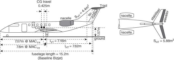
Figure 8.8 Bizjet aircraft example of empennage sizing (baseline aircraft).
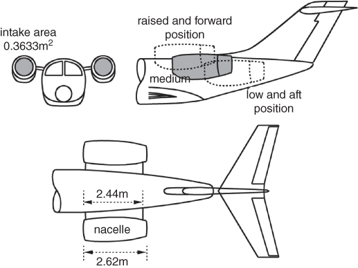
Figure 8.9 Bizjet nacelle design (baseline aircraft).
- Step 3: Compute tail arms and choose tail volume coefficients, CHT and CVT
To minimise the fuselage length, a T‐tail configuration is chosen. Subsonic jet aircraft planform shape is invariably trapezoidal with each with sweep angle, Λ1/4 = 15°, slightly higher than a wing sweep of 14° to gain in the tail arm length. Tentatively place the H‐tail and V‐tail as shown in Figure 8.8. Fuselage length = 15.25 m (50 ft).
- Measure the tail arms LHT = 7.62 m (25 ft) measured from the wing MAC1/4‐chord aircraft to the H‐tail MAC1/4‐chord and LVT = 7.16 m (23.5 ft) measured from the wing MAC1/4‐chord aircraft to the V‐tail MAC1/4‐chord. Subsequently, the static stability is to be computed about the aircraft at the forward‐most and aft‐most CG. The tail arm lengths are used to compute empennage areas.
To retain component commonality between all variants, the Bizjet tail volume coefficients are taken for the baseline variant. Typical tail volumes with the class of aircraft are taken from Figure 8.4b.
- Horizontal tail:
From Figure 8.4b, take H‐tail volume coefficients CHT = 0.7.
- Vertical tail:
From Figure 8.4b, take V‐tail volume coefficients CVT = 0.07.
- Horizontal tail:
- Step 4: Estimate empennage reference (planform) area
Compute H‐tail area, SHT, and V‐tail area, SVT, using Eqs. (6.1) and (6.2), respectively. Discard the earlier values empennage areas taken from the statistics in Step 2.
- Horizontal tail:
H‐tail area, SHT = (CHT)(SW × MAC)/LHT
SHT = (0.7 × 30 × 2.132)/7.62 = 5.88 m2 (63.3 ft2), which is about 20% of the wing area.
- Vertical tail:
V‐tail area, SVT = (CVT)(SW × wing span)/LVT,
The SVT = (0.07 × 30 × 15)/7.16 = 4.4 m2 (47.3 ft2), which is about 15% of the wing area.
- Horizontal tail:
- Discard the earlier values empennage areas taken from Figure 7.8 as done in Step 2.
- Step 5: Configure the geometric details of the empennage areas
Configure H‐tail and V‐tail planform geometries, that is, the aspect ratio, sweep, taper ratio and dihedral.
- Horizontal tail:
Take the H‐tail span to be one‐third of the wing span and the taper ratio equals 0.5 (typical in the class – designers have the choice).
- Span bHT = ⅓ × 15 = 5 m (16.4 ft)
- Aspect ratio, ARH = bH2/SH = 52/5.88 = 4.25
- Area, SH = ½(CR + CT) × b
- or 5.88 = 0.5 × 1.5 × CR × 5
- Root chord, CR = 1.568 m (5.14 ft), Tip chord, CT = 0.784 m (2.57 ft)
- Horizontal tail:
- Use Eq. (4.7) to compute the MAC.
MACH = ⅔ × [(1.568 + 0.784) − (1.568 × 0.784)/(1.568 + 0.784)] = ⅔ × (2.352 − 0.523) = 1.22 m (4 ft).
Elevator area is taken as 1.21 m2(13 ft2)) – see Step 7 that follows.
Next, settle for the H‐tail incidence αHT, if riggable, the value can be fine‐tuned after flight tests.
- Vertical tail:
It is convenient to decide the vertical tail height from aerodynamic, structural, accessibility and in certain cases to clear obstacles. Typically, it can be about a semi‐span of the H‐tail. Take V‐tail height (semi‐span) = 2.14 m (7 ft) and the taper ratio = 0.6 to bear the load of a T‐tail.
- Aspect ratio, ARV = bV2/SV = 2.142/4.4 = 1.04.
- Area, SV = ½(CR + CT) × b.
- or 4.4 = 0.5 × 1.5 × CR × 2.14.
- Root chord, CR = 2.57 m (8.43 ft).
- Tip chord, CT = 1.54 m (5.05 ft).
- Vertical tail:
- Use Eq. (4.7) to compute the MAC.
MACV = ⅔ × [(2.57 + 1.54) − (2.57 × 1.54)/(2.57 + 1.54)] = ⅔ × (4.11 − 0.963) = 2.08 m (6.8 ft).
Rudder area is taken as 0.75 m2(8.05 ft2) – see Step 7 that follows.
- Step 6: Establish control surfaces
Initially, the control areas and dimensions of the elevator and the fin are earmarked from statistics and semi‐empirical data. At this stage of study, the control surfaces can be postponed until more details are available to accurately size the control areas. In this book, the control surfaces are not sized. Subsequently, in the next design phase, when the finalised aircraft geometry is available, the empennage dimensions are established by formal stability analysis.
- Horizontal tail:
H‐tail area, SHT is shared by the stabiliser and elevator. Typically, the elevator uses 18–25% of the H‐tail area; in this case, it is 20%, which results in an elevator area of 1.21 m2 (13 ft2).
- Vertical tail:
V‐tail area, SVT is shared by the fin and the rudder. Typically, the rudder encompasses 15–20% of the V‐tail area – in this case, it is 17%. This gives a rudder area of 0.75 m2 (8 ft2).
8.9.4.1 Checking Variant Designs
To retain component commonality, the same empennage is retained, but may require some internal structural modification. It is to check the tail volume coefficients of the variant designs. The long variant with longer tail will have adequate stability. The short variant with shorter tail arm must be checked to ensure that it has tail volume coefficients.
- Short Variant
- H‐Tail With one seat pitch of 30 in. (0.762 m) plug removed from the aft fuselage LHT_short = 7.62 − 0.762 = 6.86 m (22.5 ft).
CHT_short = (SHT × LHT_short)/(SW × MACW) = (5.88 × 6.86)/(30 × 2.132) = 40.47/63.96 = 0.63, it has the range as shown in Figure 8.4b.
- V‐Tail
With one seat pitch of 30 in. (0.762 m) plug removed from the aft fuselage LVT_short = 7.16 − 0.762 = 6.4 m (21 ft).
CVT_short = (SVT × LVT_short)/(SW × wing span) = (4.4 × 6.4)/(30 × 15) = 28.16/450 = 0.0625, it has the range as shown in Figure 8.4b.
- H‐Tail With one seat pitch of 30 in. (0.762 m) plug removed from the aft fuselage LHT_short = 7.62 − 0.762 = 6.86 m (22.5 ft).
- Long Variant
- H‐Tail With adding one seat pitch of 30 in. (0.762 m) plug to the aft fuselage LHT_long = 7.62 + 0.762 = 8.382 m (27.5 ft).
CHT_long = (SHT × LHT_long)/(SW × MACW) = (5.88 × 8.382)/(30 × 2.132) = 49.45/63.96 = 0.77, it has the range as shown in Figure 8.4b.
- V‐Tail
With adding one seat pitch of 30 in. (0.762 m) plug to the aft fuselage LVT_long = 7.16 + 0.762 = 7.922 m (26 ft).
CVT_long = (SVT × LVT_long)/(SW × wing span) = (4.4 × 7.922)/(30 × 15) = 34.86/450 = 0.0775, it is with the range Figure 8.4b.
- H‐Tail With adding one seat pitch of 30 in. (0.762 m) plug to the aft fuselage LHT_long = 7.62 + 0.762 = 8.382 m (27.5 ft).
- Discussion
It was mentioned earlier that the empennage aerodynamics are the most crucial to maintain stability and aircraft control without which the vehicle is inoperable. Both the H‐tail and V‐tail have higher than wing sweep to gain in tail arm lengths to minimise empennage surface areas. The rationale is given in Chapter 6.
8.9.5 Bizjet Aircraft Nacelle – Positioning and Layout of an Engine
Being a small aircraft, there is not enough height to accommodate under‐wing nacelles, hence the aft‐fuselage‐mounted nacelle is chosen for the Bizjet example. It is important that a proven, reliable engine from a reputable manufacturer be chosen; of interest are the following. For variant aircraft, engine, thrust scaling of ±25% is desired.
- Step 1: Find engine size and select engine
Corresponding to baseline aircraft MTOM of 9500 kg, Figure 13.10a, gives TSLS/per engine = 17 000 KN ≈ 3800 lb.
There are only two engines to choose from as follows.
- Honeywell (originally Garrett) TFE731 turbofan‐series class.
- Pratt and Whitney (Canada) PW 545 series class.
- In the small engine class, Williams is coming up but is still below the required size. The Rolls Royce Viper, Adour and the Turbomeca Larzac all have a low BPR and are suited to a military application.
The Honeywell TFE731‐20 turbofan is selected being in line with Learjet 45 aircraft. The following are the pertinent details of the turbofan.
Uninstalled TSLS = 3800 lb. (≈17 000 N) per engine with BPR = 4 (small turbofan)
Engine Dry weight: 379 kg (836 lb)
Fan diameter: 0.716 m (28.2 in.)
Length: 1.547 m (60.9 in.)
- Step 2: Decide on the nacelle type
A long‐duct nacelle is chosen because it produces higher thrust to offset the weight increase of the nacelle, while also addressing environmental issues such as substantial noise reduction.
- Step 3: Configure the nacelle (Figure 8.9)
Use the relationships given in Eq. 8.1:
- Maximum nacelle diameter = 1.5 × 0.716 = 1.074 m (3.52 ft).
From Eq. 8.2, taking the factor of 0.8, compute the following.
Intake length in front of the engine face = 0.8 × 0.716 = 0.57 3 m (22.6 in.)
From Eq. 8.3, take the exhaust jet‐pipe length aft of the last stage turbine
disc = 1.0 × 0.716 = 0.716 m (2.35 ft).
Using the relation given in Eq. 8.4, the nacelle
length = 0.573 + 1.547 + 0.716 = 2.836 m (≈9.3 ft).
The nacelle fineness ratio = 2.83/1.074 = 2.64.
The keel cut is typically thicker than the crown cut to house accessories.
Using Eq. 8.5, intake the highlight area,
- Maximum nacelle diameter = 1.5 × 0.716 = 1.074 m (3.52 ft).
- The keel cut is thicker than the crown cut to house accessories. The nacelle is symmetrical to the vertical plane.
- Step 4: Positioning the nacelle with respect to the aircraft
Being a small aircraft there is lack of ground clearance for smaller aircraft. Hence the engines are mounted on the fuselage aft end, forcing the H‐tail to be placed higher. The nacelles are placed at the medium position with respect to fuselage (see Figure 8.9) at the aft end in a way the exhaust plane does not interfere with empennage and the thrust line favours aircraft stability in both the pitch and yaw plane.
- Step 5: Configure pylons to attach the nacelle to the aircraft.
Being a small aircraft, the engines are aft‐fuselage‐mounted, one at each side. At this stage, a horizontal plate may represent the pylons that support the nacelles. The pylon length = 2.44 m (8 ft) has a thickness of 25 cm (9.8 in) and a symmetrical cross‐section aerofoil‐like structure for ease of manufacture.
- Discussion
Nacelle geometry evolves around the chosen engine the Honeywell TFE731‐20 turbofan. It has conventional aerodynamic design approach housing the turbofan as discussed Chapter 12.
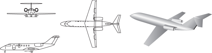
Figure 8.10 Three‐view drawing and 3D model of the Bizjet aircraft.
- Discussion
8.9.6 Bizjet Aircraft Undercarriage – Positioning and Layout
Undercarriage positioning awaits until when the location of the aircraft CG is known. It is postponed to Chapter 10 after establishing the CG position in Chapter 9. Undercarriage positions in Figure 8.8 are shown arbitrarily in this chapter.
8.9.7 Finalising the Preliminary Bizjet Aircraft Configuration
It is interesting to observe how the aircraft is gradually taking shape – it is still based on a designer's past experience but soon will be formally sized to a satisfying rational configuration to offer the best characteristics for the design.
All aircraft components are assembled using the building‐block concept to generate a preliminary aircraft configuration. To retain component commonality, the three variants maintain the same wing, empennage and nacelle geometry (some internal structures are lightened or reinforced without affecting manufacturing jigs and tools). A preliminary three‐view diagram and a 3D CAD model of the Bizjet aircraft can now be drawn as shown in Figure 8.10 as the concept definition. This will undergo iterations as the project progresses to concept finalisation. Chapter 14 sizes the aircraft to its final dimensions and finalises the configuration based on the aircraft and component mass worked out in Chapter 10.
The configuration is similar to the Learjet45 but it is not the same; there are considerable differences in configuration, component weights and performance. Readers may compare the two using Ref. [2].
The following is a summary of the worked‐out civil aircraft preliminary details (from statistics).
8.9.7.1 Consolidate Summary of Bizjet and Its Variants at this Stage of ‘Concept Definition’
- Baseline aircraft data
- MTOM: 9500 kg (≈21 000 lb)
- TSLS/engine = 3800 lb
8.9.7.2 Baseline Aircraft External Dimensions
- Fuselage (determined from passenger capacity)
- Length: 15.24 m (50 ft), upsweep: 10°
- Overall width: 175 cm (69 in.), overall height (depth): 178 cm (70 in.)
- Average diameter: 176.5 cm (69.5 in.), fineness ratio: 8.63
- Wing (aerofoil 65‐410)
- Planform (reference) area = 30 m2, span = 15 m, AR = 7.5
- Root chord, CR = 2.87 m (9.4 ft), tip chord, CT = 1.143 m (3.75 ft)
- MAC = 2.132 (7 ft), taper ratio, λ = 0.4, Λ1/4 = 14°
- Dihedral = 3°, twist = 2° (washout), t/c = 10%
- H‐Tail (T‐tail, aerofoil 64‐210 – installed with a negative camber).
- Planform (Reference) area: SHT = 5.88 m2 (63.3 ft2), span = 5.15 m (16.7 ft), AR = 4.22
- Root chord, CR = 1.54 m (5.04 ft), tip chord, CT = 0.77 m (2.52 ft)
- MACH = 1.19 m (3.9 ft), taper ratio, λ = 0.5, Λ1/4 = 15°
- Dihedral = 5°, elevator = 1.21 m2 (13 ft2), t/c = 10%.
- V‐Tail (aerofoil 64‐010) (symmetric aerofoil)
- Planform (reference) area, SVT = 4.4 m2 (47.3 ft2), height: 2.14 m (7 ft), AR = 2.08
- Root chord, CR = 2.57 m (8.43 ft), tip chord, CT = 1.54 m (5.05 ft)
- MACV = 2.07 m (6.8 ft), t/c = 10% taper ratio, λ = 0.6, Λ1/4 = 40°
- Rudder = 0.75 m2 (8 ft2), t/c = 10%
- Bare Engine (each – from statistics)
- Honeywell TFE731‐20 turbofan
- Uninstalled TSLS = 3800 lb. (≈17 000 N) per engine with BPR = 4
- Engine dry weight: 379 kg (836 lb)
- Fan diameter: 0.716 m (28.2 in.)
- Length: 1.547 m (60.9 in.)
- Nacelle
- Length: 2.84 m (9.3 ft), maximum diameter: 1.074 m (3.52 ft)
- Short Variant (all component dimensions except the fuselage length are invariant)
- Fuselage: length: 13.47 m (44.2 ft)
- Long Variant (all component dimensions except the fuselage are invariant)
- Fuselage: length: 16.37 m (53.7 ft).
8.9.8 Miscellaneous Considerations in the Bizjet Aircraft
The following are some additional considerations that could enhance aircraft performance but are not addressed here. At this design stage, none of the additional surfaces described need to be considered except the dorsal fin. All add to aircraft weight.
- Winglets. It took some time to establish the of having winglets that can reduce or induce drag – some manufacturers claim a reduction as high as 5% of induced drag (i.e. approximately 1.5% in total drag reduction), which is substantial. Currently, almost all large aircraft designs incorporate winglets. Learjet has been using them for some time and they have become a symbol of its design.
- Dorsal fin. A dorsal fin ahead of the V‐tail could work like strakes on a wing, and they are incorporated in many aircraft – at least to a small degree. They prevent the loss of directional stability.
- Ventral fins: These fins come in pairs at the aft end of the lower fuselage. Not all designs have delta fins; they are used if an aircraft shows poor stability and/or control problems. Aircraft with a flat, rear‐loading, raised fuselage upsweep demonstrate these problems and delta fins are deployed to resolve them. A good design should avoid incorporating delta fins; however, on some designs, drag reduction can be achieved with their installation.
Sometimes, at the tail end, an additional vertical surface is given below the fuselage. The single surface ventral fin also serves as a skidding structure to protect the fuselage from damage at excessive early rotation, which causes tail‐dragging.
Several external‐surface perturbations on aircraft add to parasitic drag, including antennas, inspection‐hatch covers, vent pipes and lightning dischargers. Engine and system intake and exhaust ducts and vents also increase drag.
It is suggested that readers determine whether there are any innovative requirements that should be incorporated in the conceptual design. Trends should be investigated continually for ideas to improve on aircraft design.
MILITARY AIRCRAFT
8.10 Prerequisite to Initiate Military (Combat/Trainer) Aircraft Design
The approach to conceptual design for military aircraft differs from civil aircraft study. Section 2.5 outlined that, instead of any market studies, the MoD (Ministry of Defence) floats an RFP or AST. The essential prerequisites to initiate conceptual design of a new military aircraft are (i) having the aircraft specifications requirement based on capabilities to stay ahead of potential adversary something not fully known and the (ii) new advanced technologies level to be adopted those have to be proven on scale down model technology demonstrator before they can be accepted. These prerequisites are outlined as follows. Any mid‐course change of technology level could severely affect cost.
- A combat role has a wide spectrum of activities, as outlined in Section 7.8. In general, close support/ground attack aircraft (no afterburning engines) are subsonic with quick turning capabilities, whereas air superiority aircraft have supersonic capabilities with afterburning turbofans. Predominantly, engines are buried in the fuselage; hence, there is no wing relief benefit.
- Modern supersonic combat aircraft configurations show a considerable amount of wing‐body blending. It becomes relatively difficult to identify the delineation between the fuselage and wing. The manufacturing joint between the wing section and fuselage block is a good place to make the partition, but at the conceptual phase the manufacturing philosophy is unlikely to be finalised. For classroom purposes, one way to decouple the wing and fuselage is to see the blend as a large wing root fairing that allows the fuselage to separate when the fairing part is taken as part of the wing.
- Dominantly, all payload is externally mounted except for bigger designs, which could have an internal bomb load. Modern military aircraft have external load that is contoured and flushed with mould lines. Internally mounted guns are permanent fixtures. Training military aircraft pylons to carry external load are not taken as permanent fixtures. Consumables (e.g. firing rounds) are internally loaded. In general, for long‐range missions, there is more than one crew and some consumables meant for the crew.
- Military designs are technology specific and as a result, unlike civil design, military designs exhibit large variations in statistical distribution.
For control reasons it could have additional surfaces. There are three possible choices (see Section 7.14) as follows: the (i) one‐surface configuration, (ii) two‐surface configuration and (iii) three‐surface configuration.
Stealth features are integral to current combat aircraft deigns. The basic concept of stealth is to reduce the aircraft signature to enemy sensing – more details are given in Section 18.10.3. The F16 is nearly a four‐decades‐old design and does not have stealth features. The F117 Nighthawk is an early stealth design; its configuration shows the difficulty associated with stealth design. Designing a stealth configuration is beyond the scope of this book. Bearing this in mind, a military trainer aircraft design study is given here, exposing some major considerations for combat aircraft design.
A generous wing root fairing is used to reduce interference drag as well as vortex intensity at the aft‐fuselage flow. A large aircraft BWB is an extreme example that eliminates wing root fairing problems. There is no analytical expression to specify the fairing curvature – a designer should judge the geometry from past experience and CFD analysis, considering the internal structural layout and the associated weight growth. In principle, a trade‐off study between weight growth and drag reduction is needed to establish the fairing curvature. At this stage, visual approximation from past experience is sufficient: Observe the current designs and make decisions.
- Aircraft specifications requirement
The following are the given specifications.
- Operational strategy – choice of mission profile (see Section 7.8).
- Number of crew – heavy workload could demand twin crew (typically in bombers and sometime in multi‐role combat aircraft).
- Manoeuvre limits – positive and negative ‘g’ limits – maximum 9 g.
- Armament load – weapons type for the mission role.
- Performance – maximum speed, agility/turn capabilities, altitude, range, super‐cruise (sustained supersonic flight), survivability.
- Takeoff and landing field lengths.
- Number of engine and type (BPR/afterburning) and with full authority digital electronic control (FADEC). To specify engine with vector thrust or not.
- Wing position – high or low wing.
- Systems specification – electronics, weapon system management, data acquisition, countermeasures, electronic warfare, communication, navigation, control/FBW and so on.
- Structural philosophy – type of material (aluminium/special alloys/composites).
- Specify manufacturing philosophy.
- Offer variant designs in diversified military operational role.
- Life cycle – cost/maintenance/logistics/disposal – support from cradle to grave.
- 2 Technology level to be adopted
- Aerodynamics – aerofoil sections of the various lifting surfaces (profile, t/c ratio). Type of high‐lift devices. Choice of high‐lift device will affect wing area and, as a consequence, MTOW. Wing and empennage configuration concept – one‐, two‐ or three‐surface (Figure 7.28). Contour fuselage cross‐sections accommodating engine with matched intake. Stealth aerodynamics.
- Structures – choice of material; extent of metals used, extent of composites used. (aircraft MTOM can be made lighter by appropriate material selection).
- Power plant – type and number of power plants required (low BPR).
- Undercarriage – decide on the undercarriage type and its articulation kinetics.
- Systems – type of control and extent of automation (FBW, FADEC etc.). (electrical, electronic, mechanical, hydraulics, pneumatics).
- Instrumentation – flight‐deck instruments, automation to alleviate pilot work load.
- Flight deck – establishes the layout philosophy for ease of crew operation, offers the crew comfort and protection.
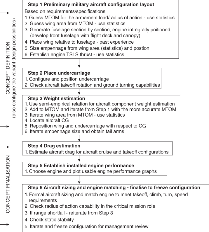
Methodology to freezing military aircraft configuration (Phase I, conceptual study). - Manufacturing philosophy – the success of new aircraft design considerable on the manufacturing technology adopted to minimise cost (Chapter 16). Aircraft parts and subassemblies must be easy to manufacture with low part count in a cost‐effective manner.
8.10.1 Starting‐Up (Conceptual Definition – Phase I)
Unlike the civil aircraft with a New Aircraft Project Group in a company, the conglomerates for new military projects have large separate divisions to work in harmony with many different organisations. The dedicated division conducts a conceptual phase of military aircraft design progress in an IPPD environment (see Section 8.4).
The military aircraft design methodology is outlined in Chart 8.2, which differs from Chart 8.1 for civil aircraft in Step 1, after that the routine is about the same. The general approaches to military (combat) aircraft starts with guessing MTOM from statistics obtained from weapon load as payload and the radius of action as range. Combat aircraft return to the base station and therefore the definition of range is not similar to the range of civil missions, unless the aircraft is used for ferrying without weapons load.
8.10.2 Methodology for Shaping and Laying Out of Conventional Two‐Surface Military Aircraft
This section takes a closer look of the Phase I stage of a new two‐surface military aircraft project as given in Chart 2.2. This chapter deals only with Step 1 of the Chart 8.2. Thereafter. typically, the process cascades down from concept definition to carrying out the concept finalisation in a step‐by‐step manner as given next.
Typically, a concept definition of new aircraft combat configuration methodology starts with generating proportionate sketches (preferably as 3D models using CAD) of the concepts proposed by the New Combat Aircraft Project Group, incorporating new ideas hitherto not seen as operational aircraft. While relying in past experiences is essential, the new configurations present challenges to the aircraft designers on account of complexities involved. After series of ‘design reviews’, once a sketch of the new aircraft configuration is agreed to, the formal methodology starts.
A lot of statistical information on military aircraft has been captured within Section 7.12. These statistical data proves very informative at the conceptual design stage to get an idea what options a new design can incorporate to stay ahead of competition with a superior product. The readers may have to wait until the project is completed to compare how close it is to the statistical data.
Armament payload weight is given as per the specification. From statistics of past designs, payload requirement gives a preliminary guesstimate of MTOW. Thereafter, from other statistics of wing area, engine size are obtained. From these geometrical parameters and the specified mission range, the fuel weight can be computed. These are eventually sized to exact values (Chapter 14) through iterations, a routine procedure dealt with in this book.
The objective at the start‐up is to guess preliminary aircraft geometry of the new aircraft. Step 1 is based on guesstimates using the statistics of past designs. Military aircraft layout methodology (Step 1 of Chart 8.2) can be summarised as given next and are dealt with in detail in Sections 8.14–8.6:
- From the statistics of armament load – radius of action, obtain a preliminary MTOW that will be improved through iterations.
- From the statistics of MTOW versus wing area, develop a preliminary wing planform with the specified technology level. Next, position the wing with respective to the fuselage in an approximate position from the past experience (typically to begin with the MAC1/4 close to middle of fuselage). Size and position the empennage in relation to wing area (readers may study comparable existing designs). This gives the preliminary wing loading, W/Sw, which can be compared with the statistics of comparable operating aircraft. It is to be noted that moving wing position will also move the aircraft CG, therefore some iterations are required.
- Select engine from what is available. The thrust loading, T/W, is considerably higher than the civil aircraft design. Combat aircraft T/W ≈ 0.8 to 1.2 and trainer aircraft T/W ≈ 0.4 to 0.6. For propeller powered aircraft, divide the thrust by 3.5 to get the SHP. Later, the engines will be properly sized to match the aircraft.
In the process, the preliminary geometry, weight and engine size will be revised to better accuracy leading to the final design (Step 6 of Chart 8.2), in an iterative process.
8.10.3 Shaping and Laying out of Military Aircraft Components
The objective is to generate aircraft components, piece by piece in a building‐block fashion, and mate them as shown in the middle diagram of Figure 2.3. The approach to laying out civil aircraft given in Section 8.3.2 also applies to military aircraft design and hence not repeated here. The seven graphs shown in Figures 7.23 and 7.27 capture all the pertinent aircraft data taken from [2] and other sources.
However, the approach to configure military aircraft densely packed fuselage differs from civil aircraft hollowed shell fuselage design. Due to not having a constant cross‐section along the length, these will have to be developed section by section. Military aircraft engines are buried into aircraft at the aft end, hence they have an air‐breathing intake duct integral to the fuselage. Current design practices either have side intakes or a belly mounted chin intake. A bubble canopy is preferred.
Combat aircraft with supersonic capability have a pointed fuselage front end. Since a combat aircraft fuselage houses the power plant, its aft end is boat‐tailed to the size of the exhaust nozzle. The current tendency blends the fuselage with the wing having with or without strakes.
Configuring combat aircraft is not as straightforward as making a civil aircraft concept definition. To stay ahead of any potential adversary, a new generation of combat aircraft incorporates new designs not seen before. As a result, configuring a new design is unlikely to follow a routine approach and, in general, there is no fixed methodology to start with.
A three‐view diagram from the 3D model should show the conceptualised aircraft configuration. Making 2D drawings (i.e. three‐view) from 3D models is simple with a few keystrokes. A preliminary configuration will change when it is sized. Military aircraft configuration gets revised more frequently. Having CAD 3D parametric modelling allows changes to be easily, quickly and accurately incorporated. At go‐ahead, the proposed aircraft offers initial guarantee of the aircraft requirements to satisfy the MoD.
Subsequent sections give step‐by‐step methodology to configure aircraft components. These are then assembled and readied for the first iteration.
8.11 Fuselage Design (Military – Combat/Trainer Aircraft)
Unlike a civil aircraft that has a ‘hollow’ fuselage for passenger/cargo accommodation, the combat aircraft fuselage interior is densely packed with fixed equipment, contoured in a varying cross‐section along its length. Note the positioning of fuel storage and engine placement. An air‐breathing intake duct (no nacelle) is integral to the fuselage as engines are buried into it (Figure 5.2). Each fuselage cross‐section is different, typical in today's trend of having fuselage sides that blend with the wing – the mouldlines could vary from design to design, but the considerations are about the same. The blending of fuselage with wing makes the fuselage contribute to body lift; improved area distribution reduces transonic drag and provides better wetted‐area‐to‐volume ratio and a thicker wing root.
8.11.1 Considerations Needed to Configure a Fuselage
The following are general considerations important for the fuselage layout.
| Geometry | Aerodynamics |
|
|
| Structure (affecting weight and external geometry) | Systems |
|
|
8.11.2 Methodology for Fuselage Design
Every military aircraft fuselage design differs with its special requirements. The aircraft reference line is set at the tip of the nose cone and fuselage axis line. For manufacturing purposes, the design concept aims to make the fuselage in modular sections.
The aircraft fuselage is conveniently split up into sections (typically into four for a aft‐mounted jet engine but can be into three sections for a front mounted propeller engine). Since the engine is housed in the fuselage, the intake configuration is integral to the fuselage. The pilot flight‐deck section may be configured first as this part is relatively easier; the fuselage flight‐deck section height width and length are have some standard sizes. The ogive/conical nose cone is installed in front of flight‐deck section, accommodating the radar diameter. The load‐bearing mid‐fuselage is the difficult one in which to get a streamlined mouldline that will have wing box/joint, undercarriage storage bay and engine inlet duct. The aft fuselage is also relatively simple to configure; accommodate the engine (turbofan), the cylindrical jet pile and the exhaust nozzle and shape it to accept empennage integration.
There is no unique method to generate a complex combat aircraft fuselage. A typical method is to split the fuselage as shown in Figure 5.26. It shows the fuselage is split into four sections, as (i) the nose cone housing radar and other electronic boxes with length Lcone, followed by (ii) crew station/flight‐deck section with length Lfront, followed by (iii) the load‐bearing mid‐fuselage to which wing and main undercarriage are attached with length Lmid and, finally, (iv) aft fuselage with length Laft, which is frequently split to reach the engine for it MRO needs.
The crew station/flight‐deck section split is behind the rear crew seat in a vertical or inclined plane not cutting the intake if they are at the fuselage sides. However, the split goes through the under belly mounted intake.
After the engine is selected and its dimensions are known, the fuselage can then be configured to house the engine at the aft end, one/two pilots and avionics at the front end and fuel in the centre between the two intake ducts.
Using the sketch made for the new combat/trainer aircraft the fuselage is made modular. Note that although the fuselage is configured in sections, they maintain the surface tangency match between the sections as of the sketch. Given next is a step‐by‐step methodology to configure the fuselage with this kind of split arrangement.
- Step 1: configuring the crew station/flight deck
Start with configuring the crew station/flight‐deck section of length Lfront. Decide on the crew seating arrangement if there is more than one, that is, side‐by‐side or tandem seating. It is important that cockpit width should be generous to have an ejection seat escape with adequate pilot space, even under restrained conditions. A minimum of 90 cm is required but a metre width of cockpit interior width is recommended. There has to be adequate space below the floorboards for cable and armour plate for protection at all sides, which increases fuselage width and height dimensions.
- Step 2: front fuselage closure (configuring the nose cone)
Next, take up the nose cone to house the radar that can be of about 1 m in diameter and other electronic boxes within the length Lcone. The nose cones (or some kind of ogive shape) have front fuselage closure to a point for supersonic flight and some to rounded bluntness for subsonic flight. The fuselage reference plane may be positioned at the tip of the nose cone. Establish the fuselage axis.
- Step 3: configuring the mid‐fuselage
The load‐bearing mid‐fuselage to which the wings and main undercarriage are attached with a length Lmid and have an attachment arrangement to have a spine going through the aft end.
- Step 4: Aft‐fuselage closure (configuring the aft end)
Aft fuselage with length Laft, which is frequently split to reach the engine for its MRO needs. Sequentially, place the four fuselage subsections along the fuselage axes. Aft‐end shape depends on the type of aircraft configuration chosen. It can have plane engine exhaust plane as the aft end or may have a closure short in length. Fuselage aft‐end closure should allow for aircraft rotational ground clearance. Military aircraft have rapid rotation. The fuselage clearance angle, θ, depends on the main‐wheel position of the undercarriage relative to the aircraft CG position (see Chapter 7). The typical angle for θ is around 16° to approach high CLmax at aircraft rotation.
8.11.3 Structural Considerations for the Fuselage Layout
- The front fuselage cone. This has the length Lcone and the provision to swing open for radar inspection and maintenance.
- The crew station/flight‐deck section. This has the length Lfront, closed to air tightness by the front bulkhead with a radar mount ahead of it and rear bulkhead behind the pilot (rear pilot for tandem seating arrangement).
- The load‐bearing mid‐fuselage. This has the length lmid and serves as the backbone of the aircraft. Here, the wings are attached and undercarriage is installed.
- The aft end of mid‐fuselage. This may have provision to attach a spine going through the aft fuselage with engine attachment points and has the empennage assembled on it. The aft fuselage must have a structural arrangement for engine maintenance and removal for overhaul.
8.12 Wing Design (Military – Combat/Trainer Aircraft)
Wing design is the most important component of the military aircraft. The wing planform shape needs to be established based on the operational requirements (e.g. hard manoeuvres, supersonic capabilities, short field performances etc.). Unlike civil designs, there is a large option for planform shape. Fuel tankage space is restricted.
Subsonic military aircraft, for example, trainers and aircraft with a CAS/COIN role, follow roughly the same methodology as Section 8.5 for civil aircraft wing design. In this section, the supersonic wing design methodology is briefly outlined as it is beyond the scope of this book.
8.12.1 Considerations in Configuring the Wing
The following are general important considerations for designing the wing:
| Geometry | Aerodynamics |
|
|
| Structure (affecting weight and external geometry) | Systems |
|
|
The first task for wing design is to select a suitable aerofoil suitable for the desired aircraft performance characteristics. After obtaining the MTOM from the statistics of existing aircraft (see Figure 7.23), the next step is to get the wing reference area and engine thrust requirements, also initially from statistics (see Figure 7.26).
Combat aircraft operate at much higher ‘g’ loads, both in pitch and lateral manoeuvre. Military aircraft with the same flight Mach number require a higher sweep and low aspect ratio to cater for manoeuvre and other considerations. A delta and its derivative wing planform shape allows high leading edge sweep for supersonic flight operation. Section 4.18.1 gives the generic wing planform choice derived from the basic triangular delta wing for military aircraft. The dominant main wing planform shape is that of a delta or its variant; the low aspect ratio trapezoidal shape also is a candidate.
A military aircraft designer would seek low aspect ratio to have rapid manoeuvre capability. The V‐n diagram (see Section 8.7) determines the strength requirement in pitching manoeuvres creating maximum stress from the bending moment at the wing root. A delta derivative wing planfom has a CT < < CR suiting structural designers to cater for high bending moments arising from hard manoeuvres. Choice of material and aerofoil t/c ratio contributes to structural integrity.
In summary, the supersonic capability of fighter aircraft demands a thin aerofoil (t/c 3–6%), high leading‐edge sweep and low aspect ratio to negotiate high g manoeuvres that will minimise wing root bending moment. It would restrict span growth but encourages a large wing root chord of delta or trapezoid with a strake planform.
High sweep, small aspect ratio, thin supersonic aircraft wing‐aerofoil camber variation along wing span, wing twist and dihedral/anhedral considerations are taken together to minimise drag and low speed handling capabilities. The design considerations are complex and not dealt with in this book. This book deals only with subsonic military trainer aircraft with a CAS variant.
Subsequently, the wing will be sized to the requirement (see Chapter 14). Some iteration is required because component weights are revised at the stages of the study. In coursework activity, one iteration is sufficient.
8.12.2 Methodology for Wing Design
- Subsonic Wing
- The wing and empennage designs follow almost the same step‐by‐step procedure as for the civil aircraft design, hence they are not repeated here.
- Supersonic Wing
- This is not dealt with in this book, so just an outline is given next. The readers may revisit Sections 4.13, 4.14 and 4.19.
- Step 1: Decide the aerofoil section
Decide on a suitable thin aerofoil of the type given in Figure 3.26.
- Step 2: Establish wing reference (planform) area
Guess the wing reference area, SW, from the estimated MTOW (Figure 7.26).
- Step 3: Establish wing geometric details
Decide on a delta derivative wing planfom shape (Figure 4.1). For classroom usage, keep the wing twist and dihedral/anhedral angle at 0°. For high and mid‐wing configurations, an anhedral angle of 1–2° may be given; low is kept at 0°.
- Step 4: Position wing with respect to fuselage
Positioning of the wing relative to the fuselage is an important part of configuring an aircraft. This is an iterative process dictated by the location of the aircraft CG at a desired position, expressed in terms of a percentage of the wing MAC. It has similar considerations as discussed in Section 8.5.2. It requires knowledge of the CG position and its range of movement with weight variation (i.e. fuel and armament load). Because the aircraft weight distribution is not yet established, it is initially estimated based on experience and past statistics in the aircraft class. With FBW system architecture, the static margin is small, nearly zero, and it even may be slightly negative. At this stage, the wing MAC1/4 is placed behind the centre of fuselage. Subsequently, the wing position must be iterated after the aircraft‐component weights are known and the wing is sized.
- Step 5: Establish wing high‐lift devices and control surfaces
In general, combat aircraft incorporate similar sorts of high‐lift concepts at the wing leading and trailing edges as used in transport aircraft. Combat aircraft high‐lift devices are less complex than multiple element Fowler type devices used in large commercial transport aircraft. In addition, high performance combat aircraft have vectored thrust capability for short takeoff and/or taking off from unprepared airfield. For landing, drag chutes are deployed. On an aircraft carrier landing, arrester cables are used. This book does not size these surfaces but schematically earmarks their position on the wing.
Combat aircraft with two‐surface configurations have all‐moving H‐tails and have a stabilator/taileron (see Section 5.2.3). A flaperon serves as both a flap and an aileron. Strake A three‐surface configuration aircraft have a canard serving not only as control surface but also providing vortex lift to the main wing. Combat aircraft also have airbrakes for quick deceleration from high to low speed.
8.13 Empennage Design (Military – Combat/Trainer Aircraft)
Subsonic military aircraft empennage design methodology is about the same as given in Section 8.6. Supersonic combat aircraft is considerably more complex and is beyond the scope of this book. Some general considerations regarding supersonic military aircraft empennage design are briefly outlined to assess the complexities.
The military aircraft shorter fuselages have shorter tail arm. A higher rate of manoeuvre demands relatively large empennage areas as well as operation in a smaller stability margin. For stealth consideration (radar signature), the elimination of the V‐tail is desirable. If this is not possible, then reduce the area with twin‐canted V‐tails and position above the fuselage to get blanketed. The F22, F14, F15, F18, MIG29 and SU30 all have twin V‐tails; the B2 does not. Older designs with T‐tails have receded from combat aircraft design. (Use of canard and vector thrusting is a strong contribution for pitch control.)
Today's military aircraft incorporate the proven technology of FBW system architecture (MIL1553 bus); therefore, the computer is flying the aircraft within the safe envelope; hence, empennage size can be reduced to the smallest size using the contribution derived from flying with relaxed stability margins for all three axes of flight. A good knowledge of aircraft control laws is required at the conceptual design stage. However, this book does not venture into an area, which goes beyond its scope when such information is lean.
On account of a high demand for control authority, the empennage design requires special considerations. The H‐tail is made as all‐moving stabilator. In case of an inadvertent situation of stabilator failure, provision is kept to split into stabiliser and elevator as a measure of redundancy to ensure safety and fly back to base. It can also be made to serve as ‘taileron’ with differential movement at each side. A V‐tail is large and, if required from structural and stealth considerations, can be split in to two. FBW system do not allow aircraft to stall. Many high performance fighter aircraft do not recover from spin and in case they flip into spin, then ejection is the routine procedure.
8.13.1 Considerations in Configuring the Empennage
The following are general considerations important for configuring the empennage (two‐surface configuration):
| Geometry | Aerodynamics |
|
|
| Structure | Systems |
|
|
8.13.1.1 Typical Values of Tail Volume Coefficients
A coarse guideline to progress is first to establish the category of aircraft under design consideration as laid down in Table 8.4. Once the class is identified, the following may prove helpful.
- Supersonic category (military combat aircraft). This category of aircraft have short tail arms and considerably lower aspect ratios with high control authority demands to execute extreme manoeuvres. Modern fighter aircraft tail volume coefficients are not readily available in the public domain. Some third‐ and fourth‐generation aircraft tail volume coefficients (a very large spread) are given in [6]. A single surface delta wing does not have H‐tail as it is merged with the wing and has LHT. For the complexities involved, combat aircraft design is not dealt with in the scope of this book. While the statistics of combat aircraft tail volume coefficients are not given here, Table 8.4 gives a usable range for military trainer aircraft design.
Table 8.4 Military trainer aircraft tail volume coefficients.
| CHT ≈ 0.6 ± 0.05 | SH/SW ≈ 0.3 ± 0.05 |
| CVT ≈ 0.07 ± 0.01 | SV/SW ≈ 0.2 ± 0.05 |
8.13.2 Methodology for Empennage Design
- Step 1: Decide on the aerofoil section
Generally, both the H‐tail and V‐tail have a thin symmetrical aerofoil section. The t/c ratio of the empennage is close to the wing‐aerofoil considerations.
- Step 2: Position the wing with respect to the fuselage – two‐surface configuration
From statistics, obtain the tentative empennage areas. Decide if the V‐tail area is required to be split into a twin V‐tail configuration. This preliminary area is needed to position the empennage with respect to fuselage to compute tail arms. Find the empennage area geometry using a typical aspect ratio and taper ratio and span. Fuselage‐mounted low H‐tail positioning is done in conjunction with positioning the V‐tail with an all‐moving H‐tail. The empennage areas will be revised in Step 4, based on empennage areas computed using the tail volume coefficient obtained from stability Eqs. (6.1) and (6.2).
- Step 3: Compute tail arms and choose tail volume coefficients, CHT and CVT
From the positions of empennage carried out in Step 2, measure the tail arms LHT from the wing MAC1/4‐chord aircraft to the H‐tail MAC1/4‐chord and LVT from the wing MAC1/4‐chord aircraft to the V‐tail MAC1/4‐chord. Use tail volume coefficients, CHT and CVT (if not available – see [6]). Military trainer aircraft tail volume coefficients are given in Table 8.4. Industries also use the tail volume coefficients, CHT and CVT, from their own databanks of statistics, substantiated by flight tests.
- Step 4: Estimate empennage reference (planform) area
From the tail volume coefficients, CHT and CVT, obtained in Step 3, compute the H‐tail and V‐tail planform areas using Eqs. (6.1) and (6.2). Discard the earlier values empennage areas taken from statistics in Step 2.
- Step 5: Configure the geometric details of the empennage areas
Configure the H‐tail and V‐tail planform geometries, that is, the aspect ratio, sweep, taper ratio and dihedral.
- Step 6: Establish control surfaces
Initially, the control areas and dimensions of the elevator and the fin are earmarked from statistics and semi‐empirical data.
All these parameters are decided from stability considerations and eventually fine‐tuned through CFD analysis and wind‐tunnel testing, with the hope that flight test results will not require further tweaking. Subsequently, static stability is to be computed about aircraft the forward‐most and aftward most aircraft CGs.
8.14 Engine/Intake/Nozzle (Military – Combat/Trainer Aircraft)
A good perspective of where the engine is installed inside the fuselage is shown in Figure 8.13. If there is more than one engine, these are kept closely coupled within the fuselage to minimise asymmetric thrust in case one engine fails. Section 6.14 may be reviewed on combat aircraft intake design considerations. Details of engine intakes and nozzles are described in Sections 18.8.
Military engines do not have large BPR, hence a bare engine diameter is smaller. Mission profiles are throttle dependent during training/operation. Weapons release involves serious considerations for CG shift, aerodynamic asymmetry and store separation problems. These are tackled through careful analysis using CFD and wind‐tunnel testing.
Intake: As indicated earlier, combat aircraft have engines buried inside the fuselage and do not have podded nacelles. It makes the term nacelle redundant; instead the term intake is used. A single pitot type intake (e.g. MIG21) at the aircraft nose is no longer pursued on account of high inlet drag. Chin mounted intake and side intakes reduce duct length, hence the inlet drag is favoured. Weapons release involves consideration for locating the intake position. Supersonic inlets are briefly discussed in Section 12.8.2 but no design work has been undertaken.
Nozzle: As the engine is mounted at the end fuselage, the exhaust jet pipes are shorter in relation to fuselage length. It goes right up to the fuselage end. There could be significant problems with engine exhaust entrainment interfering with the low H‐tail. A pen‐nib type fuselage profile could save weight by limiting the exhaust pipe length.
8.14.1 Considerations in Configuring the Intake/Nozzle
Being housed within fuselage, there is no pod/nacelle. The following are general considerations important for configuring the intake/exhaust nozzle:
| Geometry | Aerodynamics |
|
|
| Structure (affecting weight and external geometry) | Systems |
|
|
8.14.2 Methodology for Configuring the Intake/Nozzle
Supersonic and subsonic intake designs differ in their approach. Supersonic intake design is complex dealing with shock waves. Supersonic intake has to cater for a wide range of air mass demand for the full flight envelope. Doors are required to match airflow demand (see Sections 5.16.1 and 12.8.2). This book deals with subsonic intakes. Given next is a stepwise procedure for intake design.
- Step 1: Decide the type of intake and the intake position
The current dominant types are chin mounted or side mounted intakes. This book deals with side mounted intakes, placed above for low‐wing configuration or below for high‐wing configuration. An engine buried inside the fuselage requires fuselage side intakes with bent ducts joining the engine on the centreline. An intake duct with a gradual bend should not exceeding 6° at any point enables the engine position. The bends should be gentle to avoid separation, especially at asymmetrical flight attitudes.
- Step 2: Size intake area
From the rated engine air mass flow, size the intake throat area. At this stage take 90% of the engine fan face area. If the fan face diameter is Dfan, the intake area ≈ 0.95 × π(Dfan/2)2. Each of the side intake areas will be half of it as follows.
- The corners of the intake are filleted to reduce pressure loss. Its fuselage side may match the fuselage curvature.
Chin mounted subsonic intake area is as follows.
- It can be kidney shaped as in the case of F16, or can be kept ‘boxy’ with filleted corners.
- Step 3: Other installation considerations associated with intake design
Side intakes must have some form of fuselage generated boundary layer bleed arrangement. The simplest arrangement is to have splitter/diverter plate (see Figure 5.35). To keep the CG forward, the engine position should be brought as far forward as possible for the layout without creating excessive intake duct curvatures – here is where design experience counts.
- Step 4: Integrate intake to the fuselage
Being integral to fuselage, intake shaping is taken along with configuring fuselage to generate cross‐sections that generates a smooth streamlined shaped design.
8.15 Undercarriage (Military – Combat/Trainer Aircraft)
Chapter 10 is dedicated to the undercarriage. Military configuration study also requires some iteration to position the empennage and undercarriage with regard to the wing because initially the CG position is not known. Weights are estimated from a provisional positioning, and then the positions are fine‐tuned through iterations when the CG is known.
8.16 Worked‐Out Example – Configuring Military AJT Class Aircraft
As can be appreciated, from the discussions given in a marginal way in the preceding sections, combat aircraft design exercises at undergraduate level are not recommended. This kind of advanced work on combat military designs can be carried only when the basics are well mastered, that is aim of this book. The authors believe that without the considerations described here, a modern combat aircraft design exercise in the classroom would prove no better than an advanced military trainer aircraft with close support capabilities to familiarise the student with a typical mission profile and associated design consideration. Therefore, this introductory book starts the military design exercise with trainer aircraft as an alternative to frontline combat aircraft design. This simpler introductory design exercise offers sufficient design training towards the readers' understanding of military aircraft combat aircraft design. To quote examples, readers are requested to study aircraft such as the BAe Hawk, MB345 (Italy), MIG AT (Russia), L159 (Czech), YAK 130 (Russia), EAD Mako and the Korean KT50 . All these aircraft have versions for lead‐in training to the operational level, as well as a version with light combat capabilities.
In this book, a methodology on military aircraft design considerations is given with worked‐out examples of an AJT with a CAS aircraft. Military trainer aircraft, along with a CAS role variant, is a class of military aircraft, which will give some idea of the terminologies and considerations associated with military aircraft design. Therefore, the term military aircraft in this book deals with military trainer aircraft with at least one variant in the combat role.
The worked‐out AJT example is restricted to the turbofan‐powered Hawk class trainer with a single‐seat CAS variant. This single‐seat CAS variant is obtained by taking out one pilot along with associated instruments and equipment to reduce weight by about 200 kg. However, the CAS version has more advanced avionics, including forward‐looking radar making the MTOM heavier than the fully loaded AJT mission load. The AJT has two MTOM, one at Normal Training Configuration (NTC) with no armament; its mass is represented by NTCM (Normal Training Configuration Mass) and the other, with full training weapon load using all hard points represented by MTOM. CAS has only one MTOM with a full combat armament load. Training weapons are different from combat weapons: the former are low‐cost practice weapons. The concept of TTOM is introduced in Section 7.10.5.
Military designs require some early decisions on how to configure the aircraft. In general, details can come with the AST of the RFP from the MoD. In this case, a tandem seating arrangement (instructor's seat raised) with a high wing is desired by the Air Force (manufacturers may be consulted). A high wing is considered to be superior for aerodynamics and accessibility. The following are the AJT specifications used in this book.
It is important that a proven reliable engine from a reputed manufacturer should be chosen. There is only one engine in the market that will give this range of thrust; the RR‐Turbomeca Adour 861 with 0.75 BPR gas turbine and its variant Adour 951 for the CAS version. The Honeywell ATF120 could compete but this study takes the established, proven engine installed in BAe Hawk, constantly being upgraded to stay abreast with technology.
AJT Specifications/Requirements – as per RFP/AST
- Basic mission: Combat training in jet aircraft up to operational conversion.
- Payload: two 80 kg pilots and 1500 kg of practise armament.
- High visibility raised rear seat of tandem arrangement.
- Training mission: Sortie duration of a maximum of 75 min plus 30 min reserve. Two consecutive sorties without refuelling is desired.
- Engine: one turbofan with low BPR – no afterburning.
- Manoeuvre limits: +7 to −3.5 g for the training mission without armament at NTCM.
- Manoeuvre limits: +6 to −3 g for the armament training mission at MTOM.
- Maximum level speed = 0.85 Mach at 25 000 ft in clean configuration.
- Never exceed speed, VD = 620 kt (0.95 Mach).
- All‐digital flight deck.
Since the variant design has also to be considered, its details are provided as listed next. (In‐flight refuelling training is desired by some air forces, but it is not dealt with in this example).
CAS Specifications/Requirements
- Basic mission: CAS.
- Payload: one 90 kg pilot and 2200 kg of armament.
- Mission Profile: Hi‐Lo‐Hi (see Chapter 11).
- Sortie duration: 100 min plus 15 min reserve.
- Engine: one turbofan with low BPR, afterburning as option.
- Manoeuvre limits: +8 to −4 g for the TTOM (lower fuel and armament than MTOM).
- Manoeuvre limits: +7 to −3.5 g for the MTOM.
- Maximum level speed = 0.85 Mach.
AJT Technology Level Adopted:
- Rear fuselage housed single engine.
- Aerofoil: NACA 64‐210 section.
- High‐lift device: Single‐slotted Fowler flap at the wing trailing edge.
- From test data, the following maximum lift coefficients are taken as given next.
Flap setting versus CLmax
| Flap/slat deflection(°) | 0/0 | 8/4 | 20/10 | 40/20 |
| CLmax | 1.5 | 2.0 | 2.2 | 2.5 |
- Engine
- The Adour 861 with 25.5kN thrust (Ref. 6.1) has length of 1.956 m (77 in.), fan face diameter of 0.56 m (22 in.), maximum depth of 1.04 m, maximum width of 0.75 m and dry weight of 603 kg (1330 lb). The uprated version Adour 951 with 29kN meant for the CAS variant.
- Flight Deck
- Electronic Flight Information System (EFIS) type pilot display.
- Material (simplified statement):
- Primary structure is all metal. Some secondary structures are composites. Weight saving is taken as 5–10% depending on the aircraft component in consideration. Trainer aircraft conceptual study requires special attention. Here, a relatively inexperienced student pilot (typically less than 200 hours) is learning to fly in a stretched flight envelope. A trainer aircraft needs to be safe and forgiving with low‐wing loading. It has to satisfy two takeoff weights (mass) conditions: at (i) NTC and at (ii) MTOM with practise weapons load. There is a discrete jump in aircraft mass with weapons load affecting aircraft handling qualities.
Every attempt should be made to conceive a design better than Hawk, at least on paper. AJT's speed capability is slightly curtailed to reduce weight – this does not degrade training obligations, but the maximum speed of the CAS (combat) variant would be slightly higher (combat variant).
As indicated earlier, to develop a new military aircraft configuration it is necessary to make scaled sketches to incorporate new concepts to select a suitable one through design reviews in IPPD environment. Once the concept of AJT is firmed up, at this stage, some idea of weights, wing size and thrust level have to extracted from the statistics and the figures will be formally sized subsequently.
- Primary structure is all metal. Some secondary structures are composites. Weight saving is taken as 5–10% depending on the aircraft component in consideration. Trainer aircraft conceptual study requires special attention. Here, a relatively inexperienced student pilot (typically less than 200 hours) is learning to fly in a stretched flight envelope. A trainer aircraft needs to be safe and forgiving with low‐wing loading. It has to satisfy two takeoff weights (mass) conditions: at (i) NTC and at (ii) MTOM with practise weapons load. There is a discrete jump in aircraft mass with weapons load affecting aircraft handling qualities.
8.16.1 Use of Statistics in the Class of Military Trainer Aircraft
Statistics given in Section 7.10.1 relate to the operational combat class. It is better to generate more refined statistics of the military trainer class of aircraft to work with the task in hand. The authors recommend that the readers make such graphs at a better resolution for the class of aircraft under consideration. Statistical data in military trainer are few and extracting information will require some experience. Readers are suggested to get as many aircraft within the class and adopting to better technology levels.
Since a trainer aircraft has to deal with two takeoff masses (at NTC and at MTO), it is convenient first to extract data for the aircraft masses using the payload as the driver, hoping that its wing and engine sizes from the statistics would give satisfactory results compared to the existing kind. These will be subsequently properly sized – this point will be emphasised again and again.
Figure 8.11 gives the statistics of payload (armament load) versus MTOM. Also shown in the graph is the OEM of the AJT. Aircraft used in the statistics are MB339 (Italy), MIG AT (Russia), L159 (Czech), Hawk (UK, NTC mass = 6100 kg) and YAK 130 (Russia). After MTOM is decided from the payload, statistics in Figure 8.12 (with large scatter) are used to obtain wing reference area and engine size. The large scatter in Figures 8.11 and 8.12 can only give an indication serving the purpose for initial guesses.
Initially, during the concept definition stage the preliminary design relies on the guesstimate from the statistics to start with. (For trainer aircraft, even radius of action is meaningless because practise ranges are normally close to base. Training mission time substitutes for range and with a practise weapons load as payload, are the statistical parameters used to obtain trainer aircraft MTOM. The training mission's endurance is nearly the same for all major air forces, in general. The requirement for a sortie is about 60–75 min (can extend to 90 min) with a reserve of 30 minutes. Two consecutive sorties without refuelling are desired.)
Figures 8.11 and 8.12 give the statistics for the advanced training aircraft class of aircraft and are not meant for its combat CAS variant. With the AJT practise armament load of 1500 kg, corresponding to this load, Figure 8.11 indicates a OEM = 3700 kg, the NTCM = 4800 kg without armament and MTOM of = 6500 kg. The values will be updated when AJT mass is computed in Chapter 9. Corresponding to the NTCM = 4800 kg, Figure 8.12 gives the wing reference area as an SW of 17 m2. The same graph gives engine size as 24KN (5390 lb); subsequently, these will be formally sized in Chapter 14.
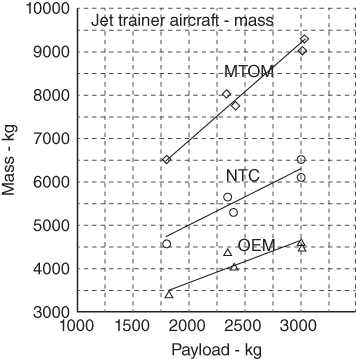
Figure 8.11 Military trainer aircraft mass.

Figure 8.12 Military trainer aircraft. Wing area and engine size.
Its CAS variant has armament load is 2200 kg. While Figures 8.11 and 8.12 are meant for the trainer class of aircraft, they are not applicable to the combat class of aircraft, some preliminary information can be extracted by adding incremental mass changes associated. The changes for the CAS are as follows.
- The OEM stays about the same, as the removal of the mass of one crew plus the ejection seat and mass saving from having a slightly shorter fuselage (see Figure 8.13) are taken up as structural reinforcement to support a higher MTOM and manoeuvring load.
- Fuel load increment, ΔFuel = 500 kg, armament load increment, ΔPayload = 600 kg, avionics and systems mass increment, ΔSystems = 100 kg, bigger engine power plant mass increment, ΔPowerplant = 160 kg. This totals mass increment, ΔMTOM = 1360 kg. Therefore, CAS MTOM is expected to be around 7860 kg. The figures would be iterated as more information is generated. The aim is to make new design better than any existing aircraft in the class. This is where the experience of designers counts.

Figure 8.13 AJT fuselage layout.
The following subsections systematically develop the preliminary configuration of the AJT.
8.16.2 AJT – Fuselage
The accepted AJT sketch is used to develop the fuselage mouldline section by section. Typically, a rear‐mounted military jet aircraft is conveniently split in to four sections as shown in Figure 5.29. The AJT fuselage is split into four sections as shown in Figure 8.13.
Since the military aircraft fuselage houses the engine, intake design is integral to fuselage layout. The choice of intake positioning is given in Section 5.16.1. In this AJT example a high‐wing configuration takes the proven type of side mounted intakes. The inlet duct area will be sized in Section 8.16.5. At this stage a statistical value is taken.
Figure 8.13 outlines in detail a tandem seating arrangement for the AJT with the instructor's rear seat raised for better view above the pupil in front. From the sketch, the overall length is 12 m (39.4 ft). Note the varying cross‐section of the fuselage housing the turbofan. Provision for internal fuel tanks is made between the two air intakes at each side of the fuselage and in the wing (Figure 8.14). The fuselage is split into front and rear sections to facilitate variant designs. The front fuselage can be replaced by single‐seat version with cockpit layout arranged to suit CAS variant. In the example, the front fuselage bears similarity with the Jaguar trainer front fuselage mouldlines.

Figure 8.14 AJT wing layout.
Intake area at side is Aint/2 = 0.117 m2 (≈1.26 ft2) as computed in Section 8.16.5. This is taken into account in developing the AJT fuselage mid‐section.
- Step 1: configuring the crew station/flight deck, length Lfront
A tandem seat with high visibility rear seat (instructor) is raised to have less obstructed forward vision. The high wing is positioned behind the rear pilot at a level that offers good look down view angle. Each seat is 1.6 m including pilot seated. Total front fuselage length = 1.6 m (front pilot) + 1.6 m (rear pilot) + 0.8 m = 4 m (Figure 8.13). Cockpit width for trainer aircraft = 0.88 m allowing the ejection seat to escape the pilot space even under restrained conditions. Fuselage width with structure thickness = 0.88 + (2 × 0.16) = 1.3 m. Below floorboard structure thickness = 0.2 m. A trainer aircraft does not have a protective armour plate.
- Step 2: front fuselage closure (configuring the nose cone)
Nose cone (or some kind of ogive shape) = 1.8 m to accommodate small radar and other electronic boxes front of the front fuselage bulkhead. The fuselage reference plane may be positioned at the tip of the nose cone. Establish the fuselage axis.
- Step 3: configuring the mid‐fuselage
The load‐bearing mid‐fuselage to which the wing Lmid = 2 m. It has the main undercarriage storage bay and bifurcated intake ducts converging to the engine face. It may have an attachment arrange with a spine going through the aft end.
- Step 4: aft‐fuselage closure (configuring the aft end)
Aft fuselage length Laft = 4.2 m: there is splitting to reach the engine for its MRO needs. Aft‐end shape depends on the type of aircraft configuration chosen. It can have a plane engine exhaust plane as the aft end or may have a closure short in length. Military aircraft have rapid rotation. The fuselage clearance angle, θ, depends on the main‐wheel position of the undercarriage relative to the aircraft CG position (see Chapter 10). The typical angle for θ is around 16° to approach high CLmax at aircraft rotation.
Place the four fuselage subsections along the fuselage axes as referenced along the fuselage reference line. The four sections fuselage adds to total fuselage length = 12 m (39.4 ft). Note that intake is integral to fuselage configuration.
- Discussion/(Rationale given in Chapter 5)
Configuring military aircraft fuselage design is different from transport aircraft fuselage design. The military aircraft fuselage houses the engine. Its fuselage has to be developed from the sketche that makes provisions for the intake duct, the undercarriage storage bay in the sketch and then aerodynamically shapes them section by section. With continuously varying cross‐sections it becomes difficult to define which diameter to use to establish its fineness ratio. The fuselage length becomes a fall‐out of the design. The pilot station deck has a standard fuselage breadth and height, but it may not have a maximum average diameter. In this example, the widest fuselage in the mid‐fuselage behind rear pilot with fuselage integrated side mounted intakes. To compare fineness ratio, a uniform dimension is to be used, possible choices are the maximum average diameter Dave where it occurs or an average value for the full length of the fuselage which will be smaller than the maximum average. Combat aircraft have supersonic capability, hence they have a pointed nose cone and its closure is the engine exit plane as the supersonic aircraft is jet propelled. For this example of a high subsonic AJT, the long pitot tube is positioned at the tip of nose cone, but alternatively there can be small pitot tubes at the both sides of front fuselage.
The military fuselage internal structural layout is considerably more complex with integrally milled frames including wing attachment. Integrally milled structures ease maintenance as they suit military operation.
The CAS variant fuselage length is 0.8 m shorter than the AJT version as can be seen in Figure 8.13. There is no credit for fuselage drag and weight reduction is taken from this slightly shorter fuselage length. CAS aircraft avionics are positioned in a way to keep its CG position with respect to the wing unaltered.
8.16.3 AJT – Wing
A high‐wing arrangement is the AST requirement – this gives better spanwise lift distribution. It also gives enough under‐wing clearance for movement and inspection. Refuelling is done over the wing. Positioning of the wing with respect to the fuselage is about in the middle. Note: a high‐wing design does not necessarily need a fairing under the wing to house undercarriage. It can be manufactured in two pieces and attached to the sides of the load‐bearing mid‐fuselage section.
MTOM of = 6500 kg is taken from the statistics as shown Figure 8.12 corresponding to the armament payload of 1800 kg. The main wing planform shape is that of a low aspect ratio trapezoidal shape. Rigorous aerodynamics optimisation to decide best aspect ratio would prove unrealistic without the structural consideration. Wing span, b, and wing area, SW, are interrelated SW = b2/AR. A high rate of roll manoeuvre restricts wing span to minimise the wing root bending moment. In practice, wing span should be decided on in consultation with structural designers. For this reason, instead of taking the aspect ratio from statistics, wing span is considered. The typical aspect ratio in this class of aircraft is within 4.5–6.
Sensitivity studies in Section 14.7 show that within the small variation (Table 14.13), a 0.1 change in aspect ratio would change about 40 kg in weight – this is relatively small amount.
- Step 1: Decide the aerofoil section
For maximum level speed = 0.85 Mach, the aerofoil section chosen is the well‐known NACA 64‐210 Design CL = 0.2.
- Step 2: Establish wing reference (planform) area
Corresponding to an MTOM of = 6500 kg, Figure 8.13 indicates a wing area, SW = 17 m2 (≈183 ft2). This gives a wing loading of 382.35 kg m−2 (≈3750 N m−2) (≈78.3 lb ft−2). These preliminary values are meant for concept definition that will be finalised by formal sizing (Chapter 16) to concept refinement.
- Step 3: Establish wing geometric details
Wing span 9.5 m (31.17 ft) is taken from statistics. This gives the aspect ratio, AR = b2/SW = 9.52/17 = 5.3, well within the statistics range. AJT is taken as trapezoid with a taper ratio, λ = 0.35 is closed due to having highest value of the Oswald's efficiency factor, e. Other parameters of interest are twist of 2° (wash out).
- Sweep
Wing sweep is taken Λ¼ = 20°. Being high wing and with 20° sweep it will have high roll stability for a military aircraft. With high sweep and lower camber the MCR is raised to 0.8 (CDW = 0) and Mcrit = 0.85 (CDW = 0.0002) compared to a Bizjet wing. (Boeing definition – see Section 3.13).
- Twist
The wing twist is taken as −2°, washout.
- Dihedral
Being of high wing and with 20° sweep it will have high roll stability for a military aircraft. Therefore, an anhedral angle of 2° is used to improve agility by reducing roll stability. It must be understood here that these form a heuristic approach to design depending on designers' experience have to be substantiated through CFD and wind‐tunnel testing. This is part of the learning process.
- Other details
Other details of wing geometry are as follows.
CT/CR = 0.35 and SW = b × (CT + CR)/2
or 17 = 9.5 × (CT + CR)/2 solving the equations
Root chord, CR = 2.65 m (8.69 ft) and tip chord, CT = 0.927 (3.04 ft).
Using Eq. (3.21), the MAC works out to be 1.928 m (6.325 ft).
- Sweep
- Step 4: Establish wing high‐lift devices
The adopted technology chose a single‐slotted Fowler flap without a LE slat that would be sufficient, saving considerably on costs. Its lift characteristics are given at the beginning of this section.
- Step 5: Position wing with respect to fuselage
AJT is configured as a high‐wing design. With a rear‐mounted engine the CG moves back. At this stage, the mid‐chord of the wing MAC½ is placed behind mid‐fuselage, say at 60% of fuselage length from the ZRP. In a conservative estimate, this may start at 58% that will iterate to better accuracy after weights are estimated in Chapter 10. Positioning of the wing relative to the fuselage is an important part of configuring an aircraft. This may not be easy because moving the wing will alter the CG position – an inexperienced engineer could encounter wing chasing.
- Step 6: Control surfaces areas and location
Control areas are provisional and are sized in Phase 2. Initially, a company's statistical data of previous experience serve as a good guideline. Aileron, flaps and spoilers are placed behind the wing rear spar, which typically runs straight (or piecewise straight) at about 60–66% of the chord. With a simple trapezoidal wing planform, the rear spar runs straight, which keeps manufacturing costs low and the operation simpler; therefore, it has a lower maintenance cost.
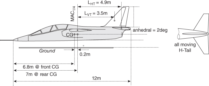
Figure 8.15 AJT tail arm (CG position guessed).
With a third of the wing span exposed, the flap and aileron areas are taken from statistics to be 1.06 m2 (11.4 ft2) and the flap area is 2.77 m2 (29.8 ft2), as the total of both sides. Single‐slotted Fowler action trailing edge flaps and leading‐edge slats are chosen. Eventual performance analysis would ascertain whether these assumptions satisfy field performance specifications, if not, the design will have to be iterated with better flap design. Figure 8.14 gives wing configuration obtained from statistics.
- Discussion/(Rationale Given in Chapter 4)
In general, the comments made in discussion at the Section 8.11.3 are valid. The AJT has a maximum operating speed of Mach 0.85 with a higher wing sweep of 20°. To cope with high g manoeuvres, the aspect ratio is kept lower to AR = 5.3 for the wing, SW = 17 m2 (≈183 ft2), resulting wing span, b = 9.5 m. Design CL = 0.2 at a training mission speed of 0.75 Mach.
8.16.4 AJT – Empennage
The AJT is configured as a high‐wing design. A military aircraft tail arm is shorter than in civil aircraft design and, along with higher rate of manoeuvre, it demands a relatively large empennage.
- Step 1: Decide on the aerofoil section
H‐Tail aerofoil NACA 64‐210, conventionally mounted on aft fuselage.
V‐Tail aerofoil NACA 64‐010, symmetric.
- Step 2: Estimate the empennage reference areas from statistics.
Estimate the H‐tail reference area SHT and V‐tail reference area SVT from the statistics. From Figure 8.4b (same as Bizjet), corresponding to wing area SW = 17 m2, (182.8 ft2), take H‐tail reference area SHT = 4.5 m2 (48.4 ft2) and V‐tail reference area SVT = 3.6 m2 (38.7 ft2). The wing areas obtained from statistics are used to measure the tail arms. These values will be discarded after obtaining the empennage areas using the relation of tail volume coefficients as done in Step 5.
- Step 3: Workout empennage planform shape, their positions and determine the tail arms
Tentatively place H‐tail at the extreme end of the fuselage to maximise tail arm and V‐tail at the aircraft plane of symmetry, slightly forward so that it is not shielded by the H‐tail (keep at least 50% rudder area free). Measure the tail arms LHT = 4.9 m (15.74 ft) from the wing MAC1/4‐chord aircraft to the H‐tail MAC1/4‐chord and LVT = 3.5 m (11.5 ft) measured from the wing MAC1/4‐chord aircraft to the V‐tail MAC1/4‐chord. These tail arms must satisfy the static stability to be computed about the forward‐most and aftward most aircraft CGs (to be established in Chapter 10).
The wing areas obtained from statistics are used to measure the tail arms. Empennage areas are still preliminary and will be iterated to final size. Figure 8.15 shows the tail arms.
- Step 4: Determine tail volume coefficients
From Table 8.4, take The tail volume coefficients are CHT = 0.7 and CVT = 0.08. The vertical tail volume coefficient is higher than the civil aircraft example to make sure that sufficient rudder is available for spin recovery.
- Step 5: Iterate empennage reference (planform) areas
- H‐tail sizing: Eq. (6.1) gives H ‐ tail reference area, SHT = (CHT) × (SW × MAC)/LHT
Then SHT = (0.7 × 17 × 1.928)/4.9 = 4.7 m2 (50.32 ft2), which is partly buried into fuselage. Discard the earlier value of SHT obtained from statistics.
This area has to be shared by the elevator and the stabiliser. Normally, the rudder takes 18–25% of the V‐tail area; in this case 20% is taken. This gives an elevator area of 0.956 m2 (10.3 ft2).
Finalise the H‐tail with other pertinent details: H‐tail area = 4.7 m2 (50.32 ft2), tail arm = 4.9 m,. With properly computed geometry, find a more accurate LHT and iterate an accurate T‐tail geometry.
- V‐tail sizing: Eq. (6.2) gives
vertical tail reference area SVT = (CVT) × (SW × wing span)/LVT
Hence, SVT = (0.08 × 17 × 9.5)/3.5 = 3.83 m2 (41.1 ft2). Discard the earlier value of SVT obtained from statistics.
Compare this with what was taken from the statistics in Step 2 – they should be close enough. Accept the values obtained by using the equations. If require, repositions of the H‐tail and V‐tail relative to the fuselage and the wing considering the aerodynamic, stability, control and structural considerations.
- H‐tail sizing: Eq. (6.1) gives H ‐ tail reference area, SHT = (CHT) × (SW × MAC)/LHT
- Step 6: Configure the geometric details of the empennage areas
- H‐tail Typically, H‐tail span is 35–40% of wing span. Taking 40% of wing span, the H‐tail is taken as 3.8 m (12.5 ft). This gives AR = 3.25. t/c = 10%, Make the H‐tail sweep, Λ¼ = 25°, taper ratio, λ = 0.3.
This gives CR = 1.9 m (6.23 ft) and CT = 0.57 m (1.87 ft).
Using Eq. (3.31), MACHT = 1.354 m (4.44 ft).
- V‐tail
V‐tail height = 2 m (Figure 8.15) and V‐tail sweep, Λ¼ = 35°.
Finalise the V‐tail design with other pertinent details: V‐tail area = 3.83 m2, Λ¼ = 35°, t/c = 10%, AR = 1.52, Span = 2.135, λ = 0.26.
This gives CR = 2.2 m (7.22 ft) and CT = 0.572 m (1.88 ft).
Using Eq. (3.21), MACVT = 1.545 m (5 ft).
Tail arm = 3.5 m (11.5 ft), keeping the fin area = 2.85 m2 (30.6 ft2), the rest being the rudder area.
With properly computed geometry, find a more accurate LVT and iterate more accurately.
Next, settle for the H‐tail incidence αHT, if riggable, the value can be fine‐tuned after flight tests.
The choices for the empennage aspect ratio, wing sweep and taper ratio are interlinked and follow the same approach as for wing design. The empennage aspect ratio is considerably lower than that of the wing. All these parameters are decided from stability considerations and eventually fine‐tuned through CFD analysis and wind‐tunnel testing, with the hope that flight test results will not require further tweaking.
- H‐tail Typically, H‐tail span is 35–40% of wing span. Taking 40% of wing span, the H‐tail is taken as 3.8 m (12.5 ft). This gives AR = 3.25. t/c = 10%, Make the H‐tail sweep, Λ¼ = 25°, taper ratio, λ = 0.3.
- Step 7: Establish control surfaces
From statistics take elevator = 1.5 m2 (16.2 ft2) and rudder = 0.9 m2 (9.7 ft2).
Initially, the control areas and dimensions of the elevator and the fin are earmarked from statistics and semi‐empirical data. At this stage of study, the control surfaces can be postponed until more details are available to accurately size the control areas. In this book, the control surfaces are not sized. Subsequently, in the next design phase, when the finalised aircraft geometry is available, the empennage dimensions are established by formal stability analysis. A worked‐out example follows in the next section.
- Discussion/(Rationale Given in Chapters 3 and 5)
AJT empennage has the same considerations as in the case for the Bizjet. Like the wing aerofoil choice, the empennage selected aerofoils are as follows.
- H‐tail aerofoil NACA 64‐210, conventionally mounted on aft fuselage.
- V‐tail aerofoil NACA 64‐010, symmetric.
- Other empennage geometric parameters are in line with wing design. Empennage sweep is taken to be higher than wing sweep to gain in tail arm lengths.
- Discussion/(Rationale Given in Chapters 3 and 5)
8.16.5 AJT – Engine/Intake/Nozzle
- Engine. The specified engine is the Adour 861 with a 25.5 kN thrust that has a length of 1.956 m (77 in.), fan face diameter of 0.56 m (22 in.), maximum depth of 1.04 m, maximum width of 0.75 m and dry weight of 590 kg (1300 lb). The uprated version of the Adour 951 has a 29 kN mean and dry weight 610 kg (1344 lb) for the CAS variant.
- Intake. As indicated earlier, combat aircraft have engines buried inside the fuselage and do not have podded nacelles. It makes the term nacelle redundant; instead the term ‘intake’ is used. If there is more than one engine, they are kept close coupled within the fuselage to minimise asymmetric thrust in case one engine fails. Figure 8.16 gives a good perspective of where the engine is installed inside the fuselage. Side intakes start just behind the rear pilot so as not to obstruct side view looking below.
Intake area at each side Aint/2 = 0.373 × (Dfan)2 = 0.373 × 0.562 = 0.117 m2 (≈1.26 ft2).
- This area is taken into account when developing the AJT fuselage cross‐sections in Section 8.16.2.
- Nozzle. Exhaust jet pipes could be longer to suit the engine position with respect to fuselage length. It goes right up to the fuselage end. There could be significant problems with engine exhaust entrainment interfering with the low H‐tail. Here, a ‘pen‐nib’ type fuselage profile could save weight by limiting the exhaust pipe length. Military engines do not have large BPR. Mission profiles are throttle dependent during training/operation. Weapons release poses serious considerations for CG shift, aerodynamic asymmetry and store separation problems. These are tackled through careful analysis using CFD and wind‐tunnel testing.
- Discussion/(Rationale Given in Chapter 5)
Military aircraft have engines embedded in the fuselage, jet propulsion aircraft types naturally at the aft fuselage. They do not have pod and the intake area is integrated with the fuselage either at the sides or as a chin mount under the front fuselage. The intake duct is shaped in a gentle curvature to avoid separation to join the circular engine face. The cross‐sections need to be developed section by section to contour lines as shown Figure 8.16. The exhaust nozzle duct is generally kept circular and straight.
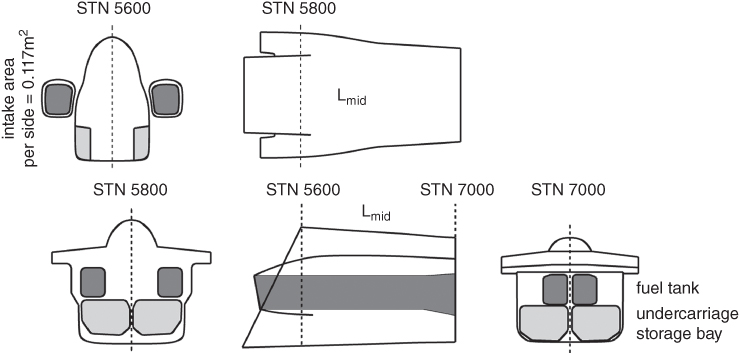
Figure 8.16 AJT intake layout.
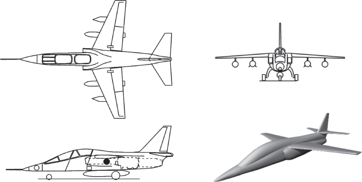
Figure 8.17 AJT three‐view drawing and 3D model.
8.16.6 Undercarriage Positioning
Chapter 10 gives the details of undercarriage (landing gear) design. Undercarriage positioning is CG dependent but at this stage the CG position is not established. Position the undercarriage, estimating the CG position and check rotational tail clearances. Make sure that the aircraft does not tip in any direction for all possible weight distributions.
The main wheels are positioned initially at about 60% of MAC (estimate). This will be revised with iteration as soon as component weights are estimated.
Figure 8.17 gives the three‐view diagram of the AJT, showing wing planform and other details.
This will be revised as soon as the aircraft‐component weights are estimated and proper CG location established. The next iteration would be after aircraft sizing (Chapter 10). The final iteration is to be carried out after performance estimation (Chapter 14). It is interesting to note how the aircraft is gradually taking shape.

Figure 8.18 AJT and its CAS variant.
8.16.7 Miscellaneous Considerations – Military Design
CG position: To keep the CG forward, the engine position should be brought as far forward as possible for the layout without creating excessive intake duct curvatures – here is where design experience counts. An engine buried inside the fuselage would require fuselage side intakes with bent ducts joining the engine on the centreline. An intake duct with a gradual bend not exceeding 6° at any point enables the engine position. The bends should be gentle to avoid separation, especially at asymmetrical flight attitudes.
8.16.8 Variant CAS Design
Figure 8.18 also gives the CAS variant of AJT with possible combinations of weapons within a disposable maximum armament load of 2300 kg. The CAS variant is derived from AJT by exchanging the two‐seat front fuselage module with a single‐seat pilot module. The CG position is unaffected by carefully positioning additional avionics black boxes, especially the forward‐looking radar at the nose.
- Predominantly, engines are buried in the fuselage; hence, there is no wing relief benefit.
- A combat role has a wide spectrum of activities, as outlined in Section 4.12. In general, Close support/ground attack aircraft (no afterburning engines) are subsonic with quick turning capabilities, whereas air superiority aircraft have supersonic capabilities with afterburning turbofans.
- Modern supersonic combat aircraft configurations show considerable wing‐body blending. It becomes relatively difficult to identify the delineation between the fuselage and wing. The manufacturing joint between the wing section and fuselage block is a good place to make the partition, but at the conceptual phase the manufacturing philosophy is unlikely to be finalised. For classroom purposes, one way to decouple the wing and fuselage is to see the blend as a large wing root fairing that allows the fuselage to separate when the fairing part is taken as part of the wing.
Dominantly, all payload is externally mounted except for bigger designs, which could have internal bomb load. Modern military aircraft have an external load that is contoured and flushed with mouldlines. Internally mounted guns are permanent fixtures. Training military aircraft pylons to carry external load are not taken as permanent fixtures.
- Consumables (e.g. firing rounds) are internally loaded. In general, for long‐range missions, there is more than one crew and some consumables meant for them.
- Military designs are technology specific and as a result, unlike civil design, military designs exhibit large variations in statistical distribution.
8.16.9 Summary of Worked‐Out Military Aircraft Preliminary Details
Chapter 11 sizes the aircraft to final dimensions to freeze the configuration. Thereafter, aircraft and component mass iteration is made.
AJT Requirement Specifications
| Payload = 1800 kg | Radius of action = 400 km |
| HSC Mach = 0.85 @ clean configuration | Initial climb rate = 40 m s−1 |
| Takeoff distance = 1100 m | Initial cruise altitude = 9 km |
| Landing distance = 1000 m | |
| Baseline aircraft mass (from statistics – needs to generated from the variant CAS design.) | |
| MTOM = 6500 kg (15 210 lb) | NTCM = 4800 kg (10 800 lb) |
| OEM = 3700 kg | Fuel mass = 1100 kg (not full tank) |
| Full tank capacity = 1400 kg | |
Baseline External Dimensions
Fuselage (deterministic from capacity) – two‐seat tandem arrangement
| Length = 12 m (39.4 ft) | |
| Maximum overall width = 1.8 m | Overall height (depth) = 4.2 m |
| Cockpit width = 0.88 m | Fineness ratio = 12/1.8 = 6.67 |
Wing AJT – NACA 64‐210.
| Aerofoil: NACA 64‐210. | |||
| Planform (reference) area = 17 m2 (183 ft2) | Span = 9.5 m (31.17 ft) | ||
| Root chord, CR = 2.65 m (8.69 ft) | Tip chord, CT = 0.927 m (3.04 ft) | ||
| MAC = 1.928 (6.325 ft) | Taper ratio, λ = 0.35 | Λ¼ = 20° | |
| Dihedral = − 2° (anhedral – high wing) | Twist = 1° (wash out) | ||
| Flap = 2.77 m2 (29.8 ft2) | Aileron = 1.06 m2 (11.4 ft2) | ||
H‐tail
Aerofoil: NACA 64‐210 installed inverted showing a negative camber.
| Planform (Reference) area = 4.7 m2 (51.45 ft2) | Span = 4.2 m (13.8 ft) |
| Root chord, CR = 1.9 m (6.23 ft) | Tip chord, CT = 0.57 m (1.87 ft) |
| MAC = 1.354 (4.44 ft) | Taper ratio, λ = 0.3, Λ¼ = 25° |
| Aspect ratio = 3.5 | Tail arm = 4 m (13.1 ft) |
| Elevator area = 0.956 m2 (10.3 ft2) |
V‐tail
Aerofoil: NACA 64‐010 symmetrical aerofoil slightly thicker t/c with higher sweep.
| Planform (Reference) area = 3.83 m2 (41.1 ft2) | Span = 2.135 m (7 ft) |
| Root chord, CR = 2.2 m (7.22 ft) | Tip chord, CT = 0.572 m (1.88 ft) |
| MAC = 1.545 m (5 ft) | Taper ratio, λ = 0.26, Λ¼ = 35° |
| Aspect ratio = 1.52 | Tail arm = 4 m (13.1 ft) |
| Rudder area = 0.98 m2 (10.5 ft2) |
Engine
| Takeoff static thrust at ISA sea level = 5390 lb. | BPR = 0.75 |
| Dry weight = 603 kg (1330 lb), | |
| Fan diameter = 0.56 m (22 in.) | Length = 1.956 m (77 in.) |
| Maximum depth = 1.04 m (3.4 ft) | Maximum width = 0.75 m (2.46 ft) |
Nacelle: None as the engine is buried into the fuselage.
CAS Variant (all component dimensions except fuselage length are kept unchanged)
Requirement Specifications
| Payload = 2300 kg | Radius of action = 300 nm |
| HSC Mach = 0.85 @ clean configuration | Initial climb rate = 50 m s−1 |
| Takeoff distance = 1400 m | Initial cruise altitude = 9 km |
| Landing distance = 1200 m | |
| CAS aircraft mass (from statistics) | |
| MTOM = 7600 kg | Payload = 2300 kg |
| OEM = 3700 kg | Fuel mass = 1400 kg (full tank) |
Fuselage – single seat
| Length = 11.2 m (36.8 ft) | |
| Maximum overall width = 1.8 m | Overall height (depth) = 4.2 m |
| Cockpit width = 0.88 m | Fineness ratio = 12/1.8 = 6.67 |
8.17 Turboprop Trainer Aircraft (TPT)
An example of a TPT aircraft is given here to get some preparation to deal with propeller‐powered aircraft design. Unlike the Bizjet and AJT examples, TPT has a front mounted engine with a propeller. This makes the CG come further forward than the other two examples and also requires propeller ground clearance in case of nose wheel collapse. Otherwise, the methodology to configure its geometry follows the same procedure as carried out in the earlier two worked‐out examples, depending on whether it is in a civil or military mission role and certified under the appropriate government authorities.
In the past, most of the air forces' pilot training was done in three tiers, starting ab initio pilot training in a small piston engine aircraft at around 1000 kg MTOW class for about 100 hours, then moving to intermediate airmanship training in jet aircraft with some weapons practise before finally moving to advanced training in AJTs. On account of streamlining training syllabi and in an attempt incorporate a more complex approach to combat training, the last four decades saw gradual changes to training syllabi in to two stages dispensing with the piston engine aircraft in the loop. Ab initio pilot training now starts with what was the intermediate level type of aircraft. A TPT presented a good compromise being in the middle of the piston engine type to fast jet propelled trainers. There are not many TPT aircraft that have been designed. It has been noticed that the TPT aircraft capability and size kept growing to COIN capability in a dual role. Some manufacturers offer both the basic version of TPT and the COIN version of TPT. But applications of the COIN version are yet to play a significant role in field action in the international geo‐political scenario as the CAS versions of the AJT do a better job.
The authors consider that the two versions of TPT should be kept separate; the trainer version trains and the COIN version is in operation. To retain commonality by maintaining one type of fleet with the COIN version in a training role, as some air forces do, is not cost effective and can become more intimidating to ab initio trainees. It is for this reason that the COIN variant is not dealt with in this book. The trainer version worked out here can be upgraded to COIN version by incorporating a bigger engine in the family, beefing‐up structures to carry more load without making any major changes to its external geometry so that the same tools, jigs and fixtures can be used with minor modifications to manufacture at low development cost. Readers may make an attempt to design a COIN variant using the information given here.
The difference between the AJT and the TPT is that the former has an aft‐mounted turbofan jet engine, hence its aft fuselage has boat‐tail closure like with planar engine exhaust plane while the latter has front mounted turbofan engine with tractor propeller developing the thrust for propulsion. The front mounted engine moves the CG forward, therefore the wing also moves further forward, below the rear pilot seat in the fuselage reference line, compared to an AJT. Due to having a front mounted engine, the nose cone section does not exist splitting the fuselage conveniently into three sections. The pilot section (cockpit) becomes the load‐bearing mid‐section.
The last one, as the third section, is the aft section with the design methodology similar to that adopted in the case of the Bizjet. Also, the tandem seat arrangement without a rear mount, as in the case of the AJT, makes the rear pilot seat less elevated so as to avoid a hump‐like fuselage mouldline that could generate undesirable streamline separation.
The methodology used suggested for a TPT concept definition can be applied to propeller‐driven civil aircraft study, of course, to be certified under civil certifying agency.
Therefore, to avoid duplication, only the worked‐out example of a military TPT is given next.
TPT Specifications/Requirements
- Basic mission: Ab initio to intermediate level military training in a turboprop.
- Low wing, tandem seating.
- Payload: two 80 kg pilots and 450 kg of practice armament.
- Maximum speed = 280 kt (472.7 ft s−1), Sustained speed = 240 kt (405.2 ft s−1).
- Training mission: Sortie duration of a maximum of 75 min plus 30 min reserve.
- Two consecutive sorties without refuelling are possible for airmanship training by taking 450 kg of fuel instead of armament for which provision for tankage capacity is retained.
- Manoeuvre: +7 to −3.5 g for the trainer version at NTCM without practise armament (fully aerobatic).
- Manoeuvre: +6 to −3 g for the fully armed version at MTOM.
TPT Technology Level Adopted:
- Rear fuselage housed single engine.
- Wing aerofoil: NACA 632‐215.
- Design CL = 0.2.
- High‐lift device: single‐slotted Fowler flap at wing trailing edge.
- From test data, the following maximum lift coefficients are taken as given next.
Flap setting versus CLmax
| Flap/slat deflection (°) | 0/0 | 8/4 | 20/10 | 40/20 |
| CLmax | 1.5 | 2.0 | 2.2 | 2.5 |
- Empennage aerofoil (both H‐tail and V‐tail) = NACA 0012
- Engine:
One turboprop engine.
There are only two types of turboprop available suitable to this proposed study. One is the Pratt and Whitney (Canada) PT6‐60A developing uninstalled 1050 SHP (dry mass = 216 kg) and other is the Garrett TPE331‐12B developing around uninstalled 985 SHP (dry mass = 185 kg). The lighter Garrett TPE331‐12B is chosen. It has length of 100 cm(44 in.), engine height = 68.6 cm (27 in.), inlet area = 0.0484 m2 (0.52 ft2) and mass rate flow =7.7 lb s−1.
EFIS type pilot display.
- Material (simplified statement):
Primary structure is all metal. Some secondary structures are with composite. Weight saving is taken as 10% as applicable to the component.
8.17.1 Use of Statistics in the Class of Turboprop Trainer Aircraft (TPT)
As the armament mass is small for the intermediate class of military training aircraft, it is better to present the ‘useful mass’ (= MTOM − OEM) as these values can be obtained from the public domain (Figure 8.19). A new design has to rely on past experiences, even if that means trying out cutting edge new advanced technologies in a scaled down prototype aircraft as technology demonstrator. It is important that readers collect as many aircraft data within the class for any new aircraft design project.
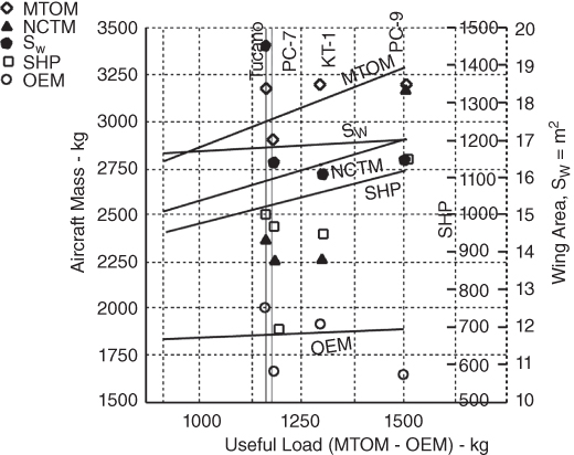
Figure 8.19 TPT statistics – (large scatter).
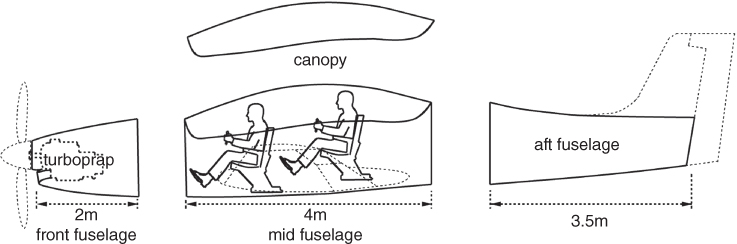
Figure 8.20 TPT aircraft fuselage layout.
Trainer aircraft has to deal with two takeoff masses (at NTC and at MTO). The NTC is meant for airmanship training and is fully aerobatic without practice weapon load. MTOM is the design maximum load for armament training. It is hoped that its wing and engine sizes from the statistics would give satisfactory results compared to the existing kind. These will be subsequently properly sized; this point is emphasised again and again.
It is better to generate more refined statistics of the TPT class of aircraft to work with the task in hand. Unfortunately, there are not many in this class TPT aircraft and the statistics shows some scatter. Given next are the statistics of four TPT class aircraft [2] (RAF Tucano, PC‐7, PC‐9, KT‐1 and PZL Orlik 130 TPTs – Figure 8.19) compared with the proposed TPT worked out in this chapter. PZL Orlik 130 is on the light TPT class. The UTVA Kobac trainer aircraft and the two‐seat version TAI Hurkus trainer aircraft data were not sufficiently available. Interestingly, PC‐7 and PC‐9 OEM are consistently lower than the other two. With only four aircraft data, regression analyses may not show a good rationale. The example worked out in his book leans towards RAF Tucano as the first author is familiarised with the aircraft. It is the modified version of the Brazilian version by Short Brothers Plc and (now Bombardier‐Shorts Belfast) and manufactured.
With the proposed TPT specification of 450 kg as practice armament and guessed fuel mass of ≈450 kg gives useful load 900 kg. Figure 8.19 indicates the corresponding masses is expected to be around MTOM = 2800 kg, wing area, SW = 16.5 ft2 and SHP = 950 as the starting point for mass and CG estimation in Section 10.18. Although the graphs shows the expected OEM = 1800 kg, NTCM = 2400 kg, these may not prove that reliable due to large scatter and are irrelevant (large scatter) at this stage. The mass estimation based on MTOM = 2700 kg will give better values. The fine‐tuned weight after proper weight estimation is likely to be different from that indicated by the statistics. The figures would be iterated as more information is generated. The aim is to make new designs better than any existing aircraft in the class. This is where the experience of designers counts.
This a good example on how to make use of a scattered data from few aircraft where the designer has to make decisions based on their experience. In such situation, a newly initiated may lean towards a known design that can be improved and subsequently compared with to establish the merits of the new design.
8.17.2 TPT – Fuselage
Since the military aircraft fuselage houses the engine, intake design is integral to fuselage layout. In this case of front mounted turboprop engine there is a small chin mounted intake (Figure 8.20) of area Aint = 0.0.8 m2 (≈0.86 ft2). The undercarriage is mounted on the low wing with its storage bay. Therefore, the fuselage mouldline has a smooth streamlined contour, hence the cross‐sections are not shown. Also the front mounted engine dispenses with the nose cone section of jet aircraft, hence the fuselage is conveniently split into three sections. The tandem seat pilot station (cockpit) becomes the load‐bearing mid‐fuselage.
Figure 8.20 outlines in detail a tandem seating arrangement for the TPT with the instructor's rear seat raised for better view above the pupil in front. The overall length is 9.5 m (31.16 ft).
- Step 1: configuring the crew station/flight deck, length Lmid
The tandem seat pilot station (cockpit) becomes the load‐bearing mid‐fuselage with length, Lmid = 4 m (13.12 ft). It has rear seat (instructor) raised to have less obstructed forward vision. Cockpit width for trainer aircraft = 0.88 m allowing ejection seat to eject with pilot under restrained condition. Fuselage width with structure thickness = 0.88 + (2 × 0.6) = 1 m. Below floorboard structure thickness = 0.2 m. A trainer aircraft does not have protective armour plate.
- Step 2: configuring the front fuselage, length Lfront
The front fuselage of length, Lfront = 2 m (6.56 ft) houses the turboprop of a bare engine length of 1 m. The chin intake is of short length position in front of the engine intake. The fuselage reference plane may be positioned at the tip of the propeller cone. Establish the fuselage axis.
- Step 3: configuring the aft fuselage, length Laft
Aft‐fuselage length Laft = 3.5 m (11.48 ft). It has a conventionally designed closure to have frames for empennage attachments. Military aircraft have rapid rotation. The fuselage clearance angle, θ, depends on the main‐wheel position of the undercarriage relative to the aircraft CG position (see Chapter 7). The typical angle for θ is around 16° to approach high CLmax at aircraft rotation.

- Place the three fuselage subsections along the fuselage reference line in a seamless manner matching the curvature of both ends.
- Discussion/(Rationale given in Chapter 5)
As mentioned in the case of configuring the AJT fuselage, military aircraft fuselage design is different from transport aircraft fuselage design. This example of a front engine mounted TPT fuselage again differs from AJT with rear fuselage mounted jet engine. TPTs have a low wing allowing undercarriage with a wider main‐wheel track. The fuselage does not have wheel storage bay as it can be accommodated thicker wing root. In this case, the wheel storage bay has to be housed in fuselage, it is taken in the wing box structure without having to show any bulge in the fuselage. TPT does not have a complicated intake with long curved duct leading to the engine face. A front mounted turboprop engine driving a propeller has a very short intake duct that keeps fuselage mouldlines with smooth contours.
Its fuselage has to be developed from the sketch section by section, keeping the smooth aerodynamic shape. The pilot station deck has a standard fuselage breadth and height. Therefore, even with varying cross‐sections, the maximum fuselage is at the rear pilot position and an average fuselage can be determined. The fuselage fineness ratio can be obtained by computing the average fuselage diameter Dave.
8.17.3 TPT – Wing
A low‐wing arrangement for the TPT is the AST requirement – this gives better spanwise lift distribution. It also gives enough under‐wing clearance for movement and inspection. Refuelling is done over the wing. The undercarriage is mounted on the wing with inward retracted storage bay. The wing planform shape is trapezoidal.
It is to be understood here that these are heuristic approaches to design depending on designers' experience and have to be substantiated through CFD and wind‐tunnel testing. This is part of the learning process.
- Step 1: Decide the aerofoil selection
For maximum level speed = 280 kt (0.465Mach) at 20 000 ft, the aerofoil chosen is the well‐known NACA 632‐215. Design CL = 0.2.
- Step 2: Establish wing reference (planform) area
The wing area SW = 16.5 m2 (177.3 ft2) is taken from the statistics as shown Figure 8.19 corresponding to the NTCM of 2350 kg. This gives a wing loading at MTOM = 169.7 kg m−2 (≈N m−2) (≈34.74 lb ft−2).
- Step 3: Establish wing geometric details
Wing span, b, of 16.36 m (53.5 ft) is taken from statistics. Wing aspect ratio, AR, is interrelated with wing span b and wing area, SW = b2/AR. This gives a moderate aspect ratio of 6.5, well within the class of aircraft suiting an ab intio training design. In practice, wing span should be decided in consultation with structural designers.
The low speed TPT trapezoid wing has zero sweep and a taper ratio λ = 0.35 that is closed due to having the highest value of Oswald's efficiency factor, e. Other parameters of interest are a twist of 2° (wash out). At this low speed, quarter chord sweep Λ¼ = 0°. For a low wing, at low speed the dihedral angle = 3° to retain some degree of agility to roll for a military trainer aircraft.
- Other details
Other details of wing geometry are as follows.
- Other details
and SW = b × (CT + CR)/2
or 16.5 = 10.36 × (CT + CR)/2 solving the equations
or (CT + CR) = 3.185
Root chord, CR = 2.36 m (7.74 ft), and tip chord, CT = 0.826 m (2.71 ft).
Using Eq. (3.21), MAC = 2/3 × [(2.36 + 0.826) − (2.36 × 0.826)/(2.36 + 0.826)] = 1.715 m (5.63 ft).
Adequate wing‐body fairing is given to reduce interference drag.
- Step 4: Establish wing high‐lift devices
The adopted technology chooses a single‐slotted Fowler flap without a LE slat that would be sufficient, saving considerably on costs. Their lift characteristics are given at the beginning of this section.
- Step 5: Position wing with respect to fuselage
TPT is configured as a low‐wing design. At this stage, the quarter chord of wing MAC1/4 is placed about at the centre of fuselage. The wing position gets iterated as the aircraft and its components are known (Chapter 10). Positioning of the wing relative to the fuselage is an important part of configuring an aircraft. This may not be easy because moving the wing will alter the CG position – an inexperienced engineer could encounter wing chasing.
- Step 6: Control surfaces areas and location
Control areas are provisional and are sized in Phase II. Initially, a company's statistical data of previous experience serve as a good guideline. Aileron, flaps and spoilers are placed behind the wing rear spar, which typically runs straight (or piecewise straight) at about 60–66% of the chord. With a simple trapezoidal wing planform, the rear spar runs straight, which keeps manufacturing costs low and the operation simpler; therefore, it has a lower maintenance cost.
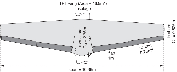
Figure 8.21 TPT aircraft wing layout.
With a third of the wing span exposed, the total flap and aileron areas of both sides are taken from statistics to be 2 m2 (10.764 ft2) and 1.5 m2 (23.68 ft2), respectively. Eventual performance analysis would ascertain whether these assumptions satisfy field performance specifications, if not, the design will have to be iterated with better flap design. Figure 8.21 gives the TPT wing control surface configuration using statistics.
- The wing could be manufactured in two pieces attached to each side of the load‐bearing mid‐fuselage.
- Discussion/(Rationale Given in Chapters 3 and 4)
TPT maximum operating speed is 280 kt, that is, ≈ 0.46 Mach at 20 000 ft altitude, when compressible effects can be ignored, hence the wing sweep is kept zero to have the best aspect ratio for the wing area, SW, =16.5 m2 (177.3 ft2) and a structurally favourable (from statistics) span, b, of 16.36 m (53.5 ft) and taper ratio λ = 0.35 that gives a high Oswald's efficiency factor, e. The aerofoil section chosen is the well‐known NACA 63‐212. Design CL = 0.5, which has forgiving stall characterises suits ab initio training.
8.17.4 TPT – Empennage
The TPT is configured as a low‐wing design. A military aircraft tail arm is shorter than a civil aircraft design and, along with a higher rate of manoeuvre, it demands a relatively large empennage.
- Step 1: Decide the aerofoil section
H‐tail aerofoil NACA 0012: conventionally mounted on aft fuselage.
V‐tail aerofoil NACA 0012: symmetric.
- Step 2: Guess empennage reference areas from statistics
The empennage planform is generally, but not restricted to, a trapezoidal shape. Being a low speed aircraft, make the H‐tail sweep Λ¼ = 0° and V‐tail sweep Λ¼ = 20° to gain the tail arm as well extend unshielded area. A strake‐like surface could be extended to serve the same aerodynamic gains as for the wing.
Empennage geometries are still not known. Therefore, guess the H‐tail reference area SHT and V‐tail reference area SVT from the statistics. From Figure 8.4b, corresponding to wing area SW = 16.5 m2 (177.3 ft2), take H‐tail reference area SHT = 3.4 m2 (36.54 ft2) and V‐tail reference area SVT = 2.2 m2 (≈23.6 ft2).
- Step 3: Workout empennage planform shape, their positions and determine the tail arms
First place V‐tail at the at symmetric plane at the end of the fuselage taking care of shielding considerations (keep at least 50% rudder area free) as described in Section 6.6.4 when the H‐tail is positioned quite ahead of it. The V‐tail may turn 1° into the propeller slipstream swirl as yaw compensation. Tentatively place the H‐tail and V‐tail as shown Figure 8.22 and measure the tail arms LHT = 5.4 m (17.7 ft) measured from the wing MAC1/4‐chord aircraft to the H‐tail MAC1/4‐chord and LVT = 5.8 m (19 ft) measured from the wing MAC1/4‐chord aircraft to the V‐tail MAC1/4‐chord. Empennage areas are still preliminary and will be iterated to final size. Subsequently, the static stability to be computed about aircraft the forward‐most and aft‐most aircraft CGs.
- Step 4: Determine the tail volume coefficients
The tail volume coefficients are CHT = 0.6 and CVT = 0.08. The vertical tail volume coefficient is higher than the civil aircraft example to make sure that sufficient rudder is available for spin recovery.
- Step 5: Iterate empennage reference (planform) areas H‐tail sizing:
Eq. (6.1) gives H‐tail reference area, SHT = (CHT)(SW × MAC)/LHT.
Then SHT = (0.6 × 16.5 × 1.715)/5.4 = 4.1 m2 (51.45 ft2), which is partly buried into fuselage. Discard the statistical value of 3.4 m2 by this new H‐tail area, SH = 4.1 m2. This area has to be shared by the elevator and the stabiliser. No stability credit is taken from the small amount of strake at the root of leading edge, but it acts as strake‐like flow modifier to delay separation at a high angle of attack.
- V‐tail sizing:
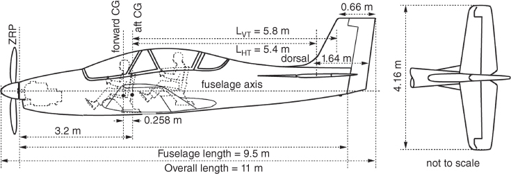
Figure 8.22 TPT aircraft tail arm.

Figure 8.23 Turboprop trainer aircraft (TPT).
This type of V‐tail configuration requires special consideration in defining the areas. It may be noted that the rudder is positioned past the fuselage to keep rudder area unshielded from H‐tail to a large extent. It is a matter of defining the areas to keep this book focused on carrying out related design considerations. The V‐tail area SVT using Eq. (3.30) gives the total area as shown shaded in Figure 8.22 plus the extra area of the rudder is kept separate. The total V‐tail area is SVT = 2.2 m2 as computed using Eq. (8.21). The shadowed area is used to determine CR‐VT, CT‐VT and the height of the V‐tail above the fuselage. This rudder arrangement keeps a large portion of it unshielded, which adds to the safety to come out of a spin hands free: an important aspect for ab initio pilot training. No stability credit is taken from the small amount of dorsal fin area, but it acts as strake‐like flow modifier to delay separation at high yaw (cross wind capability). This is a special V‐tail design consideration.
- Equation (6.2) gives vertical tail reference area SVT = (CVT)(SW × wing span)/LVT.
Hence SVT = (0.08 × 16.5 × 9.5)/5.8 = 2.2 m2 (23.3 ft2).
The extra rudder area below SVT = 0.34 m2.
The value can be retained as it came out to be the same as the statistical value.
Accept the values obtained by using the equations. If required, reposition the H‐tail and V‐tail relative to the fuselage and the wing considering the aerodynamic, stability, control and structural considerations.
- V‐tail sizing:
- Step 6: Configure the geometric details of the empennage areas
- H‐tail geometry Finalise the H‐tail with other pertinent details. The selected aerofoil gives a t/c = 12%.
Make the H‐tail sweep, Λ¼ = 0°. Typically, H‐tail span is 35–40% of wing span. Taking 40% 0f wing span, the H‐tail span = 6.54 is taken as 4.16 m (13.62 ft). This gives an AR = 4.0. H‐tail root and tip chord can be computed as done for the wing that gives the taper ratio λ = CT/CR = 0.5.
For a trapezoidal planform, SHT = b × (CR + CT)/2. This gives (CR + CT) = 2 × (4.1/4.15) = 1.976 m.
Leading to: CR_HT = 1.32 m (4.33 ft) and CT_HT = 0.66 m (2.16 ft).
Using Eq. (3.21), MACHT = 1.0234 m (3.36 ft).
Next, settle for the H‐tail incidence αHT, if riggable, the value can be fine‐tuned after flight tests.
- V‐tail geometry:
Finalise the V‐tail design with other pertinent details: Λ¼ = 20°, t/c = 12%, height = 1.375 m, λ = 0.4, fin area = 1.76 m2 and rudder area = 0.44 m2. The V‐tail root chord and tip chord lengths are given in Figure 8.22 as CR_VT = 1.64 m (5.38 ft) and CT_VT = 0.66 m (2.16 ft).
Using Eq. (3.21), MACVT = 1.22 m (4 ft).
- The choices for the empennage aspect ratio, wing sweep and taper ratio are interlinked and follow the same approach as for the wing design. The empennage aspect ratio is considerably lower than that of the wing. All these parameters are decided from stability considerations and eventually fine‐tuned through CFD analysis and wind‐tunnel testing, with the hope that flight test results will not require further tweaking.
- H‐tail geometry Finalise the H‐tail with other pertinent details. The selected aerofoil gives a t/c = 12%.
- Step 7: Establish control surfaces
- H‐tail geometry: Normally, the elevator takes 18–25% of the H‐tail area; in this case 25% is taken.
Elevator = 1.025 m2 (11 ft2).
- V‐tail geometry:
Normally, the rudder takes 18–25% of the V‐tail area; in this case 20% is taken.
This gives a rudder area of 0.44 m2 (4.75 ft2).
A TPT has a front mounted engine with a tractor propeller. In case of the inadvertent situation of nose wheel collapse, 7–9 in. tip clearance from ground is required. Undercarriage design is carried out in Chapter 9.
As in the case of the Bizjet (see Step 6 in Section ), the TPT control areas and dimensions of the elevator and the fin are earmarked from statistics and semi‐empirical data given in the next section.
- H‐tail geometry: Normally, the elevator takes 18–25% of the H‐tail area; in this case 25% is taken.
- Step 8: Engine installation and propeller ground clearance
Give the propeller ground clearance to protect against an inadvertent nose wheel collapse. A minimum of 7 in. is required. After finding the matching propeller diameter the extent will be known. For the TPT, about 9 in. is kept at this stage on the progress.
8.17.5 TPT – Intake/Exhaust
The front mounted TPT aircraft have a very short nearly intake duct leading from aircraft intake plane to the engine‐face inlet area of 0.048 m2 (0.52 ft2). Aircraft intake area is taken as slightly larger than the engine‐face inlet area.
Figure 8.23 gives the three‐view diagram of the TPT, showing wing planform and other details.
In the following are the TPT details assumed as the concept definition from the statistical data that will be finalised to the formally sized configuration in Chapter 14.
| MTOM = 2800 kg (6160 lb) | NTCM = 2350 kg (5170 lb – no armament) | ||
| OEW = 1700 kg (3740 lb) | Practise armament load = 450 kg (≈1000 lb) | ||
| Crew = 400 lb (≈180 kg) | Fuel = 470 kg (1012 lb) | ||
| Typical mid‐training Aircraft mass = 2200 kg (4840 lb) | |||
| Maximum speed = 280 kt | Sustained speed = 240 kt (405.2 ft s−1) | ||
| Fuselage | |||
| Length = 9.5 m (31.16 ft) | height = 1.6 m (5.25 ft) | ||
| Cockpit width = 0.88 m (35 in.) | Fuselage width = 1.0 m (≈40 in.) | ||
| Fineness ratio = 9.5/1.0 = 9.5 | |||
| Wing (wing aerofoil: NACA 632‐215) | |||
| Reference area = 16.5 m2 (177.3 ft2) | Span = 10.36 m (53.8 ft) | AR = 6.5 | |
| Root chord, CR = 2.36 m (7.74 ft) | Tip chord, CT = 0.82 m (3.7 ft) | ||
| MAC = 1.715 m (5.62 ft) | Taper ratio, λ = 0.35 | Λ¼ = 0° | |
| Dihedral = 5° (dihedral – low wing) | Twist = 1° (wash out), | t/c = as specified | |
| Flap = 2.2 m2 (23.6 ft2) | Aileron = 1.06 m2 (11.4 ft2) | ||
| H‐tail (NACA 0012) | |||
| Reference area = 4.1 m2 (44.2 ft2) | Span = 4.16 m (13.65 ft) | AR = 4.0 | |
| Root chord, CR = 1.32 m (4.33 ft) | Tip chord, CT = 0.66 m (2.16 ft) | ||
| H‐tail MAC = 1.0234 m (3.36 ft) | Taper ratio, λ = 05, Λ¼ = 0° | ||
| Elevator area = 1.025 m2 (11 ft2) | t/c = 0.12 | ||
| V‐tail (NACA 0012) | |||
| Reference area = 2.2 m2 (23.3 ft2) | Height = 1.375 m (4.52 ft) | ||
| Root chord, CR = 1.64 m (5.38 ft) | Tip chord, CT = 0.66 m (2.16 ft) | ||
| V‐tail MAC = 1.0234 m (3.36 ft) | Taper ratio, λ = 04, Λ¼ = 20° | ||
| Rudder area = 0.44 m2 (4.74 ft2) | t/c = 0.12 | ||
| Engine | |||
| Takeoff static power at ISA sea level = 975 shp | (Garratt TPT‐331‐12B) | ||
| Dry weight = 185 kg (407 lb) | Engine intake area = 0.048 m2 (0.52 ft2) | ||
| Length = 1.1 m (43.4 in.) | Height = 0.686 m (27 in.) | ||
COIN variant
A single‐seat COIN variant can be derived as suggested in Figure 8.24. The details are given in Section 10.18 but not worked out. The reader may give it a try.
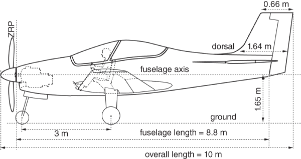
Figure 8.24 Single‐seat COIN variant of TPT.
References
- 1. Abbott, I.H. and von Doenhoff, A.E. (1949). Theory of Wing Sections, Including a Summary of Airfoil Data. New York: McGraw Hill.
- 2. Jane's All the World's Aircraft Manual (yearly publication).
- 3. Niu, M. (1999). Airframe Structural Design. Hong Kong: Commlit Press Ltd.
- 4. Talay, T.A. (1975). NASA SP‐367; Introduction to the Aerodynamics of Flight. Langley Research Center.
- 5. Torenbeek, E. (1982). Synthesis of Subsonic Airplane Design. Delft University Press.
- 6. Nicolai, L.M. and Carichner, G.E. (2010). Fundamentals of Aircraft and Airship Design. Reston, VA: AIAA.
- 7. Roskam, J., Aircraft Design, Published by the author as an 8 volume set, 1985–1990.
- 8. Jenkinson, L.R., Simpson, P., and Rhodes, D. (1999). Civil Jet Aircraft Design. Arnold Publishers.
- 9. Kundu, A.K. (2010). Aircraft Design. Cambridge University Press.